Challenge 9 : Project : Technical Surfacing Kia Sportage
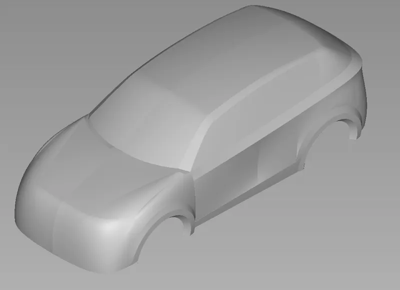
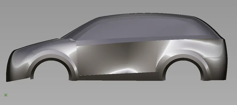
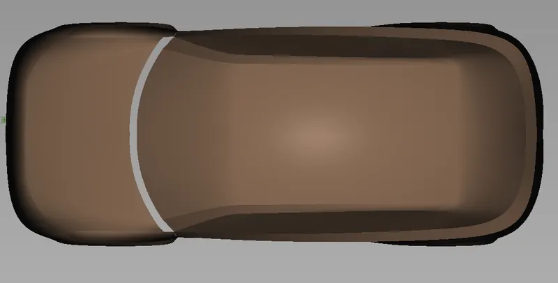
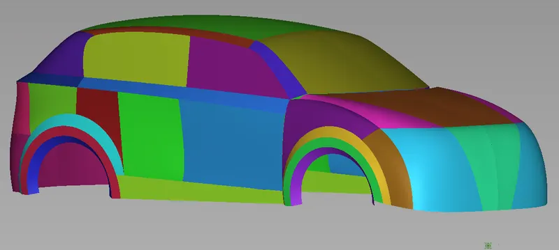
Introduction to Class-A
Class-A (or 'Strak') is a term used in specifically in automotive design. It describes the final production surface data for the aesthetic parts of the car.
The term 'Class A' is often misunderstood, but it's generally seen as the 'Holy Grail' of surface modeling. This is because as it achieves the highest surface quality levels, and it demands a high level of automotive design knowledge as well as surface modeling skills.
Class A represents the 'craftwork' end of the design process. Creating the main surface shapes to describe the vehicle is the primary design activity. But the painstaking, detailed craftsmanship of perfecting those surfaces, designing flanges and panel gaps is what guarantees that a beautiful design turns into a beautiful manufactured product.
What is Class-A?
The Class-A modeling process typically starts with a fully developed design, either as a scanned clay model or an Alias model. Because the design isn't changing, the modeler has the time to build surfaces to the highest quality standards, ready for production.
The challenge for Class-A is to combine the need for:
- Aesthetic Quality – Continuity and Highlights
- Engineering Requirements – Flanges and Fit
- Production Requirements – Modeling Tolerances
Aesthetic Quality required for Class-A
Baseline Requirements: G0, G1, G2
The baseline requirements for Class-A are the same as for production-quality surfacing in all industries: to build to tight tolerances for G0, G1 and G2 continuity.
In Alias this is achieved by using the right Construction Tolerances before you start modeling, for example 'Catia V5'.
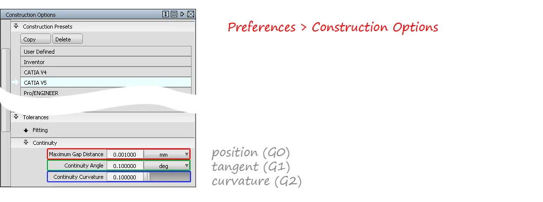
And by checking that these have been achieved using one or more of the following tools:
- Surface Edit > Stitch (to check the whole model for G0 gaps)
- Evaluation > Surface Continuity ( to check individual boundaries for G0, G1, G2)
- Evaluation > Model Check (to check the whole model for G0, G1, G2, and duplicates, small edges etc.)
It's important to note that there are no absolute rules for tolerances or continuity levels. It is part of the skill and knowledge of the Class A modeler to be able to judge which settings will result in the right quality in the production car.
G3 Continuity
Class-A aesthetic quality is generally understood as being 'perfect' highlight reflections. G3 Continuity across the surface patches is often used to achieve this. G3 continuity can be achieved with the following workflows and tools in Alias:
- Direct Modeling of the surface CVs combined with interactive evaluation of the continuity.
- Object Edit > Align

- Surface Tools: Freeform Blend, Profile Blend, Surface Fillet, Symmetric Fillet.
- Blend Curves
Evaluating Highlights
'Perfect Highlights' can't be judged by a single evaluation, instead a combination of methods is used:
- Continuity at Boundaries: Evaluation > Surface Continuity
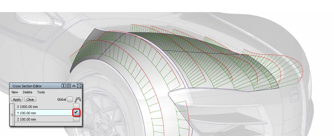
- Continuity across boundaries: Locators > Curve Curvature and Windows > Cross-Section Editor
- Continuity Flow: Diagnostic Shading > Iso-Angle and Diagnostic Shading > Light Tunnel
- Highlight Flow: Diagnostic Shading > Saddle Lines
- Surface Quality: Diagnostic Shading > Curvature Evaluation
Engineering Requirements for Class-A
These are typically defined by an automotive company, with detailed standards for each element of the design.
For example:
- Tolerances specific to A- surfaces, B-surfaces, C-surfaces etc.
- Tolerances specific for exterior surfaces, interiors (with and without grain for example).
- Tolerances specific for main blends, smaller fillets and detail fillets.
- Split Lines, Flanges and Panel gaps
It's not possible to give a generalized set of standards here, as this knowledge is part of the profession of Technical Surfacing and the proprietary expertise of each company, and so needs to be learned within the industry.
The Key to Successful Class-A Modeling
"The layout of the surface data is the key to Class A modeling." (Barry Kimball)
This means that the flow of CVs and Hulls and the flow of surface patches across the main surfaces and features of the car is the most important consideration for achieving Class A quality surface data.
This is the intention of the Golden Rules, to set out the right discipline for controlling surface quality. In particular:
- Bezier surfaces (for internal continuity/smoothness)
- G2/G3 continuity between surface patches
- Good CV Layout
- Working to the correct tolerances.
Reverse Engineering
Reverse Engineering is the process where a physical model (typically a clay) is scanned, and then rebuilt as a NURBS model.
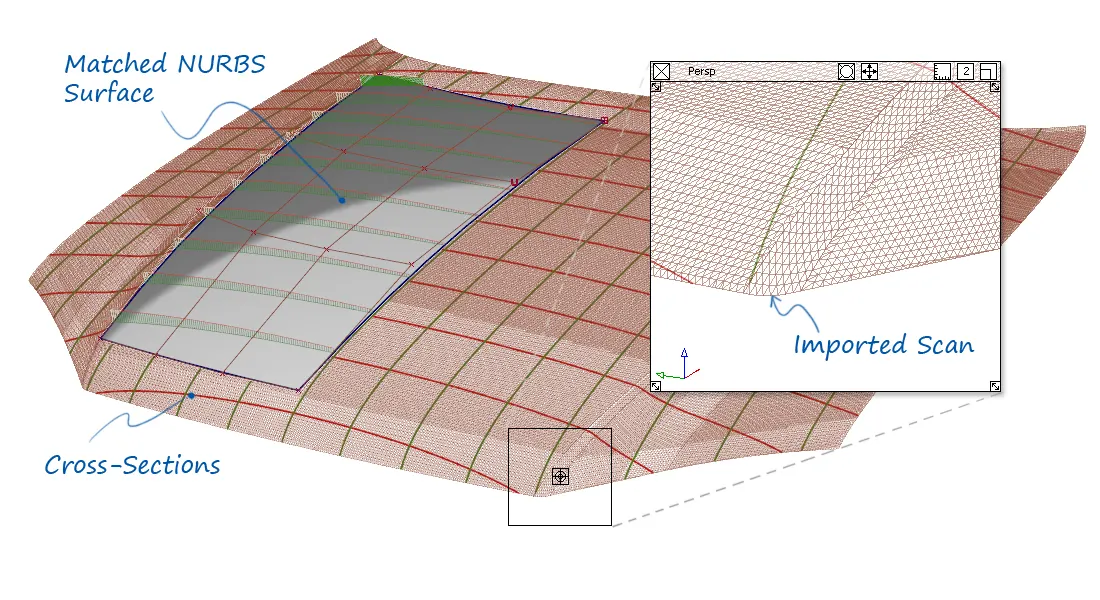
The modeler will be given a tolerance by which the NURBS data must match the scan. However, scan data will always have some imperfection, or 'noise', and there also may be imperfections in the clay model.
So the skill of the Reverse Engineer is to maintain the exact design character of the scan, whilst rejecting unintended imperfections.
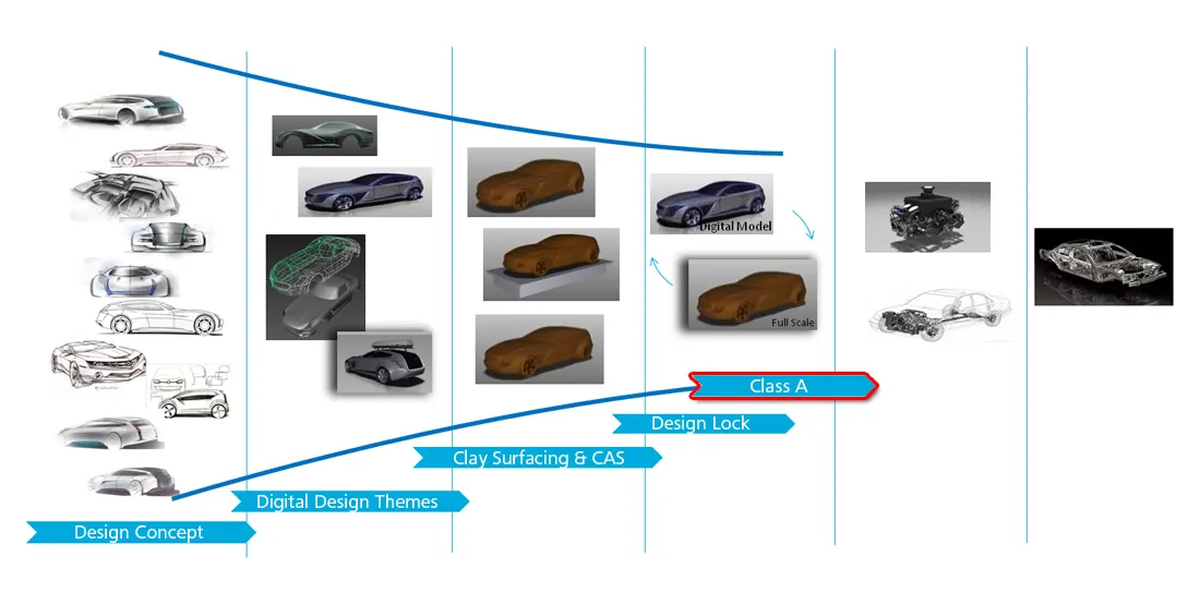
Class-A modeling is slow and methodical. Therefore it is used on the final model iteration, once the design has been 'locked'.
During Concept Modeling, the design changes are too rapid for strict Class-A standards to be applied. However, if Class-A principles are applied then the handover of data to Class-A modelers will be more effective.
Introduction
In this tutorial, you will learn how to use the Transformer Rig to change the roof of a car to give it a different centerline.
Part 1: Setting up the rig by adding targets and constraints
In this part of the tutorial, you will learn how to set up a rig to modify the roof of the car. Specifically, you will learn how to associate existing surfaces of this model as target and constraint surfaces in a rig.
-
Open
tutorialCar.wire. This file is located in the CourseWare/wire folder of the Alias downloadable help available here http://www.autodesk.com/alias-2016-help-download. -
You can see the whole car. All but the surfaces corresponding to the greenhouse (the roof, the A pillars and the B pillars) are in the layer named body and that layer is in Reference state. Click on the square on the right of the name of the body layer in the layer bar to make this layer invisible.
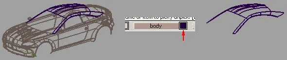
We only need to work with the surfaces of the greenhouse.
-
In the Object Edit tool palette,select Dynamic Shape Modeling > Transformer Rig to open the Transformer Rig toolbox.
-
Choose Layouts > Top to open the top view at full size.
-
Use the
 and draw a pick-box around the middle surfaces as shown in the figure, and click Accept Targets to select the roof surfaces as target geometry in the rig.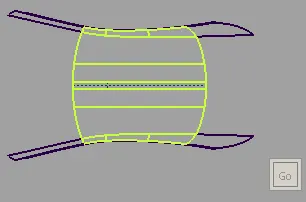
-
Click the Add Constraints tool in the Transformer Rig toolbox, and select the remaining surfaces on both sides of the roof. Click Accept Constraints to add these surfaces as constraints in the rig.
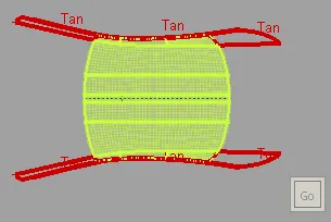
The word Tan means the constraints are all tangential constraints. The pale green dots that appear inside the target surfaces are part of the clamp visualization, and the color indicates that the target surfaces are free to be modified in the current rig.
In the Transformer Rig, any existing geometry can be used as modifiers or constraints. You can also create geometry to use as modifiers or constraints. You will do so in Part 2 of this tutorial.
-
Select the Pick > Object tool
 to leave the Transformer Rig toolbox for now.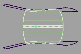
The target surfaces are picked, and they have history. History for Transformer Rig is created immediately after you have picked the initial set of surfaces as targets. Whenever you wish to re-enter the Transformer Rig tool to edit the rig, use Query Edit tool  from the Object Edit tool palette and click with the on any of the target surfaces.
Part 2: Create a new surface to use as the modifier
In this part of the tutorial, you will learn how to create a surface that will be used as a modifier for the rig you have created in Part 1. You will be shown how to create a modifier surface customized for the targets in the rig, and also customized for the modification in mind.
-
In the Curve Edit tool palette, select the Create > Duplicate Curve tool
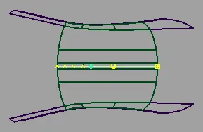
 . Use the and click on the dashed line in the center of the middle surface of the roof.
You have just duplicated the centerline of the roof.
-
In the Transform tool palette, select the Move tool
 , and using the
  , drag the curve down to below the A pillar, as shown in the figure. Leave the curve picked.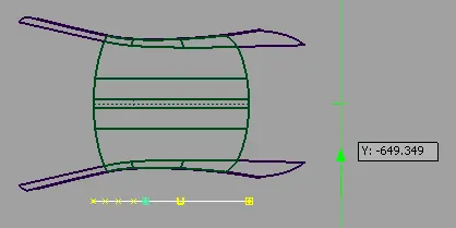
-
In the main menu, choose Edit > Duplicate > Mirror >
 , to open the option window of the Mirror Duplicate function.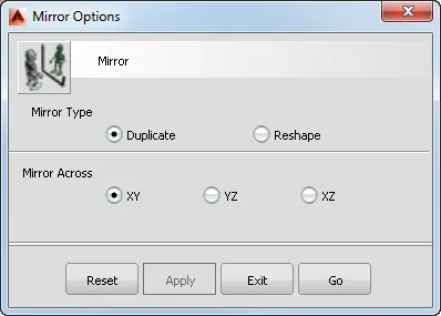
Make sure XZ is set. Click Go.
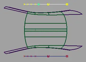
The curve is now duplicated and the new copy appears above the A and B pillars.
-
Use the
to click on the bottom curve so that both curves are picked. -
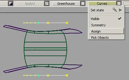
Choose Layers > New to create a new layer. Name the layer Curves.
-
Assign the two curves to the Curves layer.
-
In the Surfaces tool palette, select the Skin Surfaces > Skin tool
 . Click the bottom curve, then the top curve. A new surface is created.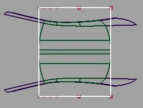
-
Choose Delete > Delete Construction History. Click Yes in the dialog that warns you about deleting history on active objects.
-
Create a new layer, name it Modifiers, and assign the skin surface to it.
-
In the Object Edit tool palette, select the Query Edit tool
. Click any target surface of the greenhouse to re-enter the Transformer Rig tool.The green and red visual highlights reappear. This indicates that you have returned to editing the rig that you have set up in Part 1 of this tutorial.
-
Choose the Add Free Modifiers tool from the toolbox, and click on the skin surface to select it.
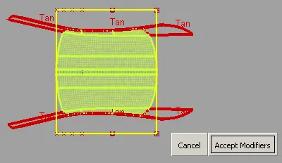
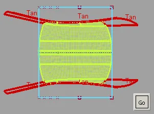
Click Accept Modifiers to confirm.
-
Click Go. A popup window may appear to notify you that the Transformer Rig history has been set up. If so, click OK to continue.
-
Choose the Pick > Object tool
to leave the Transformer Rig tool.
Part 3: Change the modifier
Now that we have completed the set-up of the rig, this part of the tutorial will show you how to use regular Alias functionality to make changes to the modifier geometry. Through Transformer Rig history updates, the target geometry (the roof surfaces) will update accordingly. This shows you the power of the Transformer Rig — your update to a single simple surface will update multiple surfaces in unison.
In this case we will use the Transform CV tool, located at the bottom of the modeling control panel. You are free to use whichever tool you are comfortable with to change the modifier surface.
-
Make the Curves layer invisible.
-
Choose the Pick > Object tool
, and use the to pick the modifier surface. -
In the Control Panel, turn on the CV/Hull option under Display. Notice that the CVs for the modifier surface are now displayed.
-
In the Pick tool palette select the Nothing tool
 , followed by the Point Types > CV tool
  . Switch to the Side view, and pick the two topmost CVs. This actually corresponds to two rows of CVs of the modifier surface.
 -
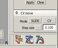
Click the Transform CV tool. Under mode, choose SLIDE.
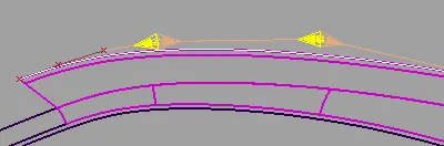
Orange and yellow arrows appear beside the selected CVs.
-
Using the
, click one of the yellow arrows in the modeling window. Drag the mouse towards the left, and notice the modifier surface becoming "flatter". Continue to slide the CVs until the leftmost arrow touches the next CV to the left, as shown here: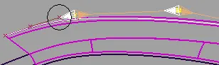
-
Release the mouse button. Notice that the target surfaces change according to the change you have made to the modifier surface.
-
To quickly compare your change to the original shape of the target surfaces, use Object Edit > Query Edit tool
to reenter the tool (see Part 2), double-click on the Transformer Rig icon in the toolbox to open the option window, and click on Show All Geometry. Optionally, turn off Draw Clamp Visualization under the Visualization section. You should then see something like this:
The green surfaces are the target surfaces post-modification. The cyan line is where the modifier is. The dark gray lines are the templated version of the original target surfaces. You can see how much you've flattened the surface.