Challenge 8
Week 8
- What are piers and explain about. Explain loads considered for calculating the total design force?
Ans. Piers are the compression members that transfers the load of superstructure to foundation. The loads considered for calculating design forces are:
- Dead Load
- SIDL
- Live load (OTOS, OTBS, BTOS, BTBS)
- Braking/ Traction
- Wind (Vert, Long, Trans)
- Seismic(Vert,Long,Trans)
- Buoyancy (if water is present)
- Bearing (friction)
- Centrifugal(if curved span)
- Temperature
Due to combination of above load Biaxial moment(Long.& Trans.), axial load and shear forces are developed in the pier for which it is designed for moment, stress and crack width.
- Explain about the DL, SIDL & LL considered for designing a pier of a metro viaduct? Also, what grade of cement is being used in the construction of piers
Ans.
- Dead load – For design of pier in a metro viaduct, it has to take self weight of pier, weight of pier cap above it, half of superstructure from left and right side spans.
- SIDL- In a metro SIDL will be transferred from superstructure which might consist of OHE mast, cables, cable trays, other electrical equipments, crash barrier, railings,rails,rail track and its attachments.
- Live Load- In metro depending on the density of population that will be travelling the gauges may differ of varying axle load.
If it is one way there will be only one track, and if to and fro is planned 2 tracks will be planned, so depending on this 4 live load conditions are considered:
One track One side (OTOS)
One track both side(OTBS)
Both track one side(BTOS)
Both track both side(BTBS)
Pier will have two sides, left and right. When Train is only on one side and when train is on both side of the pier conditions are considered for design. Both side will have maximum vertical load, one side will have cantilever effect and produce moment.
- Explain about the Braking & Traction effect and loads considered for designing a pier of a metro viaduct
Ans. When a trains stops braking is generated and when a train starts due to acceleration traction effect is produced. Braking is generally 18% of unfactored axle load and traction is generally 20% of unfactored axle load. Maximum of both is considered for design. For its exact value rail track structure interaction analysis is done.
It is a longitudinal force. As per IRS bridge rules when considering seismic forces, only 50% of gross tractive effort/braking force, to be reduced by taking dispersion and distribution of longitudinal forces, shall be considered along with horizontal seismic forces along/across the direction of the traffic.
- Explain about the Centrifugal force & Wind load considered for designing a pier of a metro viaduct explain with an example
Ans. Centrifugal force is applied for curved spans, in metro Radius is considered very large if track is straight , for curves appropriate radius is considered. It is the outward throw effect due to curved span.
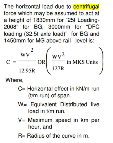
The design speed of the vehicles is 75 km/hr.
The radius of curvature in the bridge is 3 m.
CF=WV^2/127R
W=70kN (As per IRC 6, 35tx2)
V = 75km/hr
R=3m
CF = 1033.5kN
Wind Load
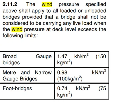

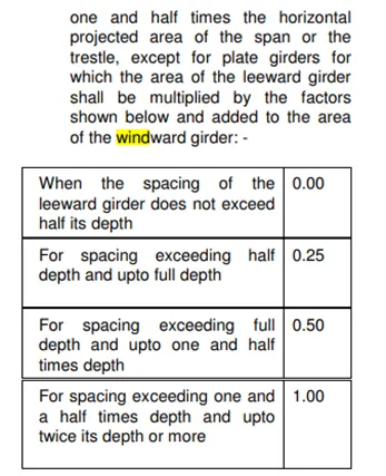
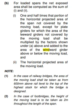
Wind load will be applied on superstructure, pier cap and open portion of pier.
The bridge is assumed to be located in chennai and is of RCC I girder type with length of bridge as 15m. The distance between piers along the bridge deck width is 10m.
Height of pier given is 7m and pier dimension is 1.5x1.5m.
The given bridge has 5 RCC I girders having flange of 0.4x0.1m and web of 0.2x0.8m. The centre to centre distance between girders is 2.5m.
WInd Load is calculated as per IS 875 Part 3.
As per the code,
Design Wind Speed Vz = Vb x k1 x k2 x k3 x k4
Vb = basic wind speed
For chennai Vb=50m/s as per Annex A
k1 = Risk Coefficient = 1.08 from table 1
Obstructions are of height less than 10m therefore terrain category 2 and height of bridge is 9m(pier+piercap+girder hts=7+1+1)
k2 = 1
Since there is no inclination k3 = 1
k4 = 1
Vz = 50x1.08x1x1x1 = 54 m/s
Wind pressure Pz = 0.6 x Vz x Vz = 1749.6 N/m2 = 1.75 kN/m2
Design wind pressure Pd = Kd x Ka x Kc x Pz
Kd = 1
Ka = 1
Kc = 0.9
Pd = 1.75x1x1x0.9 = 1.575 kN/m2
Wind in X Direction
On pier
Wx1 = Pd x width of pier = 1.575 x 1.5 = 2.36 kN/m2
On pier cap
Wx2 = pd x depth of pier cap = 1.575 x 1 = 1.575 kN/m2
The bridge will be analysed for Wind Loads.
- Explain about the Earthquake load & how the loadings are calculated as per code. Explain the three types where the seismic loads are considered.
Ans. IRS Seismic code 2017 on Seismic Design of Railway Bridges shall be followed.
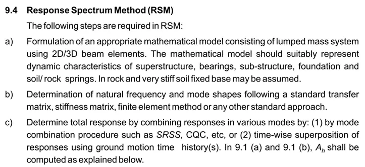
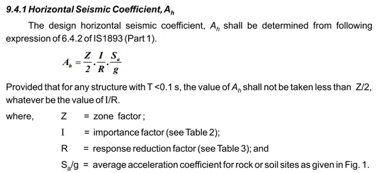
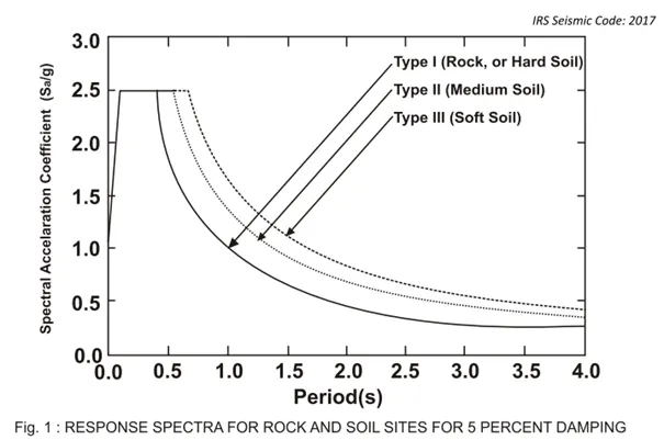

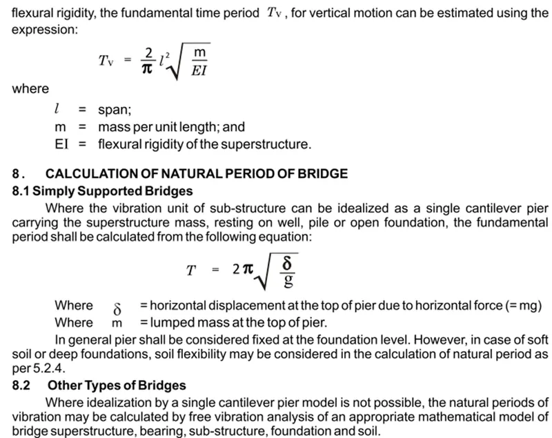
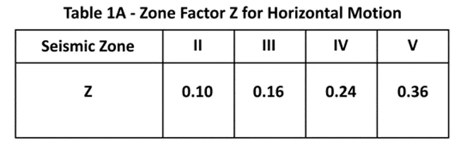
Zone as per map provided
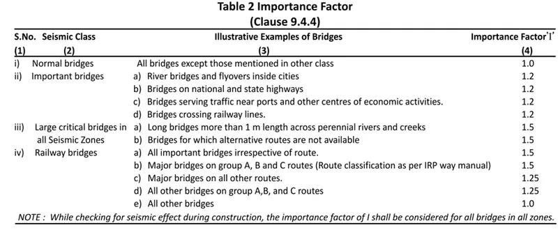
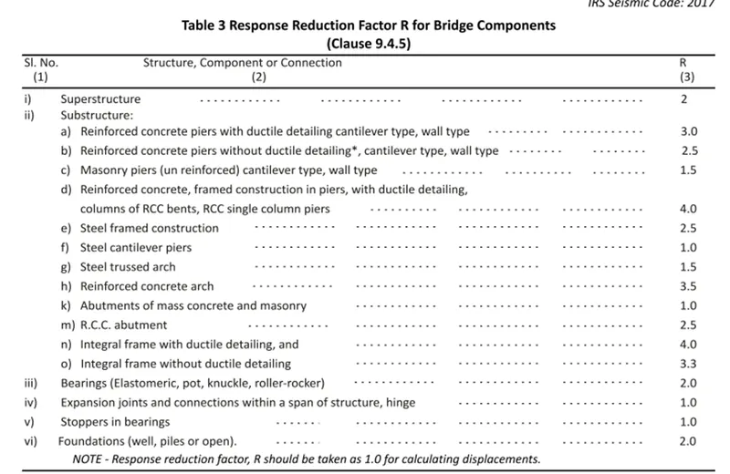
For longitudinal direction, the masses from superstructure (i.e. DL & SIDL) shall be applied at bearing top and self-weight of pier cap & pier shall be applied at their respective centroid.
The Moment of Inertia for Pier shall be taken as Ieff = 0.75 of gross moment of Inertia of pier for
Time Period Analysis.
For transverse direction, the masses from superstructure (i.e. DL, SIDL & 50% LL) shall be applied at their respective centroid and self-weight of pier cap & pier shall also be applied at their respective centroid.
Seismic Masses –
- For calculation of Time Period Live Load shall be considered excluding impact.
- Full Weight of Superstructure shall be considered for Time Period Evaluation. However,
weight of substructure shall be considered 80% of weight for obtaining the mass.
Seismic force on live load (This is in Line with IRS Seismic 2017 Clause 7.1)
- The seismic force due to live load shall not be considered when acting in the direction of
traffic but shall be considered in the direction perpendicular to traffic.
- The live load on railway bridges, to be considered as seismic mass, for calculation of
Earthquake loads in both horizontal and vertical direction, shall be taken as 50% of design
live load (without impact). In load combination also, only 50% of the live load shall be
combined with Earthquake load along with Dead Load.
As per IRS Bridge Rules, correction slip no. 22 in transverse / longitudinal seismic condition, only 50 %
of gross tractive effort / braking force will be considered.
Three types:
Earthquake load (In longitudinal direction)
Earthquake load (In transverse direction with LL)
Earthquake load (In transverse direction without LL)
- Explain about the LWR forces & Derailment loads how the loadings are calculated as per code.
Ans. Due to temperature stresses expansion and contraction will happen on the rails, for this effect to be considered in long weld rails(LWR), LWR forces are considered. LWR forces is considered to be 0.8t/m/track. It is as per UIC 774-3R.
Derailment loads are considered when train gets derailed. There are 3 conditions to be considered,
- When train tries to overturn, all the load will be on one wheel and track.
- Train may lose contact with both the rails but stays in superstructure.
- Only some bogie will derail and it may come back on track.
It is not for non-ballasted deck.
For derailment check, we intend to use ACI 358.1R92 [R17], clause No. 3.5.2 which corresponds to the application of 50% of one vehicle weight (live load)
- Explain the design combinations of the all the loads considered in a metro design through which we attain the factored BM from unfactored bending moments.
Ans.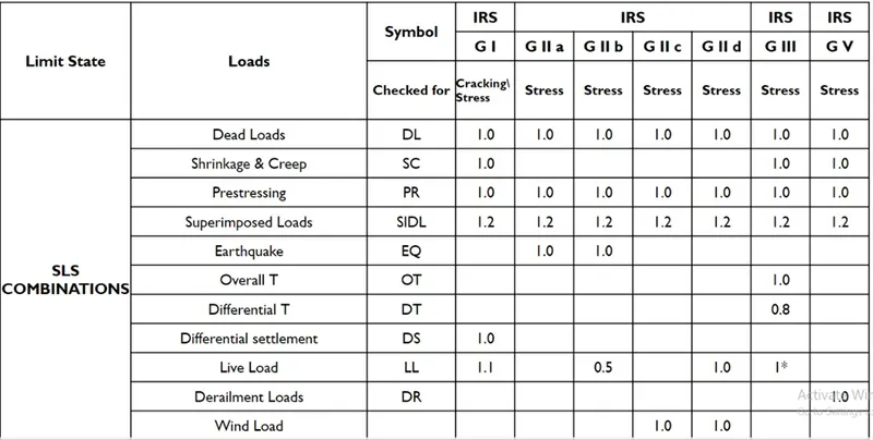
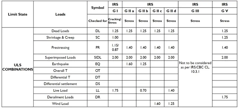
SLS 26 combinations and ULS 22 combinations are created. Temperature is not considered in ULS.
- Explain the reason behind the factored load of SIDL is higher than the factored load of DL in a design.
Ans. For SIDL factored load is higher than DL as SIDL may be weared off after certain years we will have to put extra layer of it which will increase its weight.
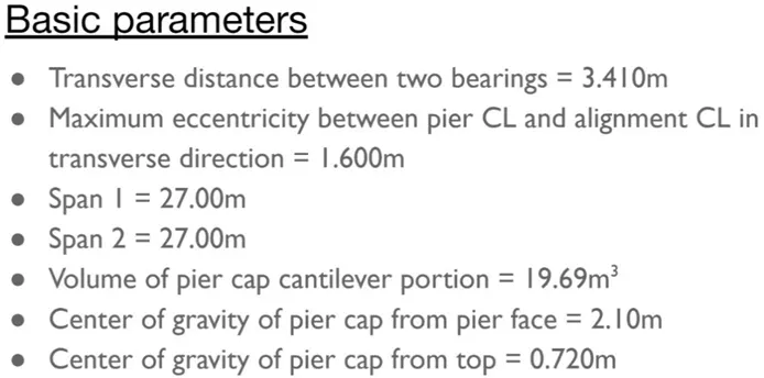
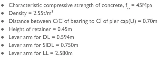
- What are the basic design parameters considered for a RCC pier cap.
Ans.
- Explain the reinforcement detailing from the result extraction in longitudinal & sectional views of a viaduct.
Ans. Top reinforcement 24 nos @ 32 mm dia bars provided as closed loop in the entire periphery of the cantilever projection.
- Next layer 24 nos @ 32 mm dia bars provided below the top reinforcement
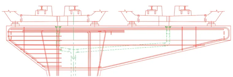
LONGITUDINAL VIEW
- Placement of drainage pipes between the reinforcement has to be taken care of, local adjustment at site can be done without reducing the number of rebars as per designer.
- Four types of rebar in the cantilever
1st main tension rebar top layer
2nd main compression rebar on the bottom layer
3rd shear rebars for shear reinforcement
4th is the outer ring which binds whole concrete core in a single unit
- Vertical rebars coming from the pier cap to pier which has to be checked for shear friction effect
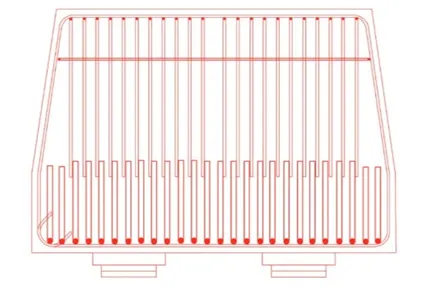
SECTIONAL VIEW
- An outer vertical link, outer horizontal link, shear links and primary rebars which are shown in slid red color.
- An additional mesh(8mm) is provided below the bearings in two layers below the pedestal.
- Mesh reinforcement helps in avoiding the direct crushing of concrete just below the jack & pedestals below the pier cap.
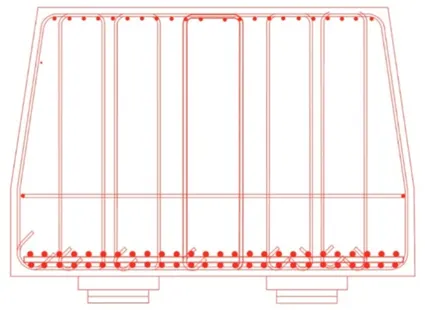
- A spacer bar acts as a bar ensures proper space between main bars, dia of spacer bar shall be minimum of main rebars.
- Shear links which are provided in the form of closed rectangular units bent at an angle of 135 degree.