Challenge 7 : Concept Modelling of Steering Wheel
Torus Options
- Sweep
-
The degrees of rotation around the center of radial primitives.
For example, if you enter 180 degrees in the sphere tool, Alias creates a hemisphere.
- Size
-
Size can be either Absolute or Relative, and determines which of the following parameters can be set.
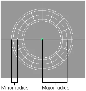
- Major radius
-
The distance between the center of the ring and the center of the tube. This option is only available if Size is set to Absolute.
- Minor radius
-
The radius of the tube. This option is only available if Size is set to Absolute.
- Ring Thickness
-
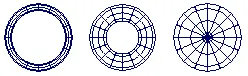
The diameter of the ring relative to the diameter of the entire torus. This option is only available if the Size is set to Relative.
As the ring thickness approaches 0.5, the hole gets smaller. At 0.5 the torus has no hole. See the following figure.
hulls
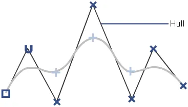
As a curve gets more spans/edit points, you might lose track of the order of the CVs. To show the relationship between CVs, Alias can draw lines between them. These lines are called hulls.
Tubular Offset Control options
- Surface
-
With the Tube option, the resulting geometry is a full tube. Using the Groove option results in the part of the tube on either side of the surfaces which the tube intersects. Choose None to create no geometry.
- Radius
-
Defines the radius of the tube. Create a variable radius interactively by adding more radius manipulators along the curve. Adjust the radius of the tube interactively by dragging its manipulator.
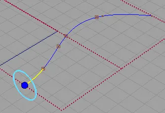
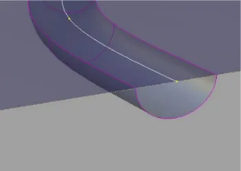
This image shows a surface created by using the Tubular Offset tool with Groove option. Notice the top surface can be trimmed to reveal the groove. This option is useful for representing parting or cut lines.
- Flip
-
The Flip option (only available if you have chosen the Groove option) enables you to flip the groove onto the other side of the input surfaces to create a bump. On-screen manipulators indicate which side the tube will be built on.
- Tangent Offset, Normal Offset
-
The tube can be offset from the original input data along the tangent from the input data, or normal to the surface from the input data. On-screen manipulators update interactively to show the position of the tube.
Surface Structure
- Surface Type
-
If you choose Single surface, a single tube surface is built. If you choose Multiple surfaces, the tube is split at curve boundaries, which also include surface boundaries, since a curve cannot span more than one surface.
If curves-on-surface are created at the edges of the tube surfaces (see Trim Type option below) they are segmented to correspond to the multiple tube surfaces.
- Bézier Surfaces
-
This option only appears if Surface Type is set to Multiple surfaces. If it is checked on, each surface will be a Bézier patch.
Bézier patches have a single span, and their maximum degree in the U direction is set through the Explicit Control section. The default is degree 5.
Control Options
- Trim Type
-
The options in Trim Type enable you to select between the creation of curves-on-surface where the tube surface intersects the base surfaces, or to automatically trim away the area of the input surfaces that is contained within the tube. If the Trim Type is set to Off, the input surfaces are left untouched.
- Auto Update
- Choose between updating changes by selecting the Update button, or automatically updating changes.
Note: If Auto Update is set off, use the spacebar to press the Update button
- Chain Select
- If this box is checked, selecting a surface curve also selects all other surface curves that are tangent continuous with it.
Controlling manipulators in Tubular Offset
Each manipulator consists of two handles — the rail slider and the radius handle — only one of which can be active at a given time. The active handle is shown in light blue. The rail slider, a "ball" sliding along the rail, indicates the position on the rail where the radius applies. The radius handle, an approximate cross section of the future surface, controls the radius at this point.
The value of the active handle is shown on the status line.
For all of the following operations, use the
 , unless stated otherwise.
- To activate a handle, click it.
- To de-activate the currently active handle and switch back to the picking mode, click anywhere on the screen (without dragging the mouse).
- To add a new manipulator,
 -click the desired point on the rail.
 - To move a manipulator, drag the slider using the . Alternatively, activate the slider and type in the position (in the range from 0 to 1) along the rail.
- To adjust the radius value, click and drag the radius handle. Once the handle is active, the mouse can be dragged anywhere on the screen. Alternatively, activate the handle and type in the radius in current units.
- To delete a manipulator, -right click it.
- If a single manipulator is used, the radius is constant, and its value can also be adjusted in the control box. As soon as another manipulator is added, the value in the control box is grayed out.
Surfaces > Swept Surfaces > Extrude
Creates a new surface by extruding a generation curve along a path curve. Normally used to make tubular objects with symmetrical cross sections.
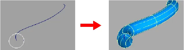
Extrude Options
- Style
-
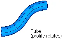
Tube – As the profile curve sweeps along the path, it pivots to maintain the same angle to the path curve.
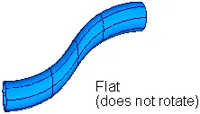
Flat – As the profile curve sweeps along the path, it maintains its original orientation.
- Create caps
-
Caps can be created at the ends of the surfaces if the extruded objects are closed planar curves.
Off – Do not create caps at the ends of the extruded surface.
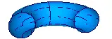
Cap Start – Create a trimmed surface to cap the first end of the extruded surface.
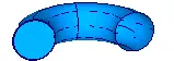
Cap Both – Create trimmed surfaces to cap both ends of the extruded surface.
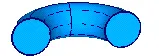
- Extrude Pivot
-
This option controls which pivot point to use when you are extruding more than one profile curve.
This option appears when Style is Tube.
Closest – Pivot the profile curves around the endpoint of the path curve closest to the bounding box of all the profile curves.
This option is the default. It works best when you have a profile curve near the start or endpoints of the path curve.
Component – Pivot each curve around its own individual pivot point.
This option works best when you want to extrude text.
- Surendra GembaliHi brother. I have a small doubt could you please help me with this