Challenge 6
- What is elastomeric bearings? And what is made of and the uses of them.
Ans. An elastomeric bridge bearing, also known as a pot bearing or elastomeric bearing, is a commonly used modern bridge bearing.
The purpose of the elastomeric bearings is to support a bridge or other heavy structure in a way that permits the load to shift slightly, in a horizontal direction, relative to the ground or foundation. Without such bearings, the bridge support might crack or fracture when it moves due to ground movements or thermal expansion and contraction. Elastomeric bearing pads compress on vertical load and accommodate both horizontal rotation and horizontal shear movement.
The internal structure of an elastomeric bearing consists of a three layers: a lower "pot" made of steel, which rests on the foundation or footing; a relatively thin elastomeric pad (a rectangle or disk shape) resting on the lower pot; and a steel plate loosely set on top of the elastomeric disk, on top of which the weight of the bridge rests. The bearings are often produced as a unit, ready to be installed.
The elastomeric pad may made from any of several materials, including natural rubber, elastomers, teflon, or synthetic rubber (such as neoprene).
Elastomeric bearing pads are the most economical solution used in construction of large span bridges and buildings.
Elastomeric bearings are often used in applications other than bridges, for example, supporting buildings that are built on soil that may shift slightly and cause a concrete load to crack in the absence of a elastomeric bearing.
- What are the importance of elastomeric bearing in the metro viaduct?
Ans. For Spans upto 30m elastomeric bearing has proven to be successful. The steel inside it provides rigidity and rubber provides elasticity. In metro viaduct since there is a heavy live load movement there is lateral and vertical translation of the superstructure which may develop high stress and that is transferred to the substructure, that develops crack width also which is a risk thereby the life of bridge reduces. Elastomeric bearing helps the structure to dissipate stress during the load transfer from superstructure to substructure. It also allows the little bending when there is vertical loading and also allows lateral movement under permissible limits.
- What are the design input parameters need for the designing of the elastomeric bearings? Explain the inputs that shall be provided by the vendor/material supplier?
Ans. For design of bearings input parameters needed are:
- Span Length
- C/C of bearing
- Concrete & Steel properties
- Superstructure properties (Area, Moment of inertia)
- Reaction of permanent loads(Dead Looad, SIDL), variable loads(Live load, braking/traction),Wind seismic etc from superstructure.
- Translation & rotation of superstructure at bearing location.
- Creep, shrinkage & temperature translation.
All the load values are extracted for maximum load combinations as per IRC CBC
Inputs provided by material supplier will be the properties of elastic material & steel that will be required for the project. As per the loading provided by the designer the vendor should suggest the size and thickness of the bearing for its initial design.
- What are the design loads that are considered for the design of bearings?
Ans. Design Loads considered for design of bearings are:
- Dead Load
- SIDL
- Live Load
- Lateral load(Wind, Seismic, Braking/traction)
- Creep, Shrinkage
- Temperature
Where DL & SIDL are permanent loading, Creep & Shrinkage produce long term effect on the concrete.
- Explain in detail the calculation of design of bearings with the various conditions considered.
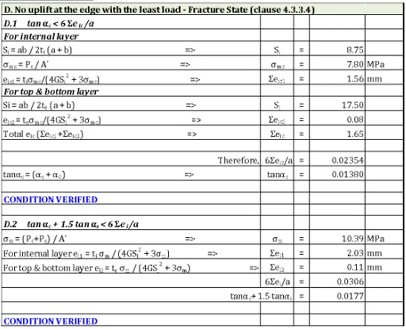
Ans. For design of bearing various conditions are considered as per IRS CBC for maximum and minimum load cases as follows:
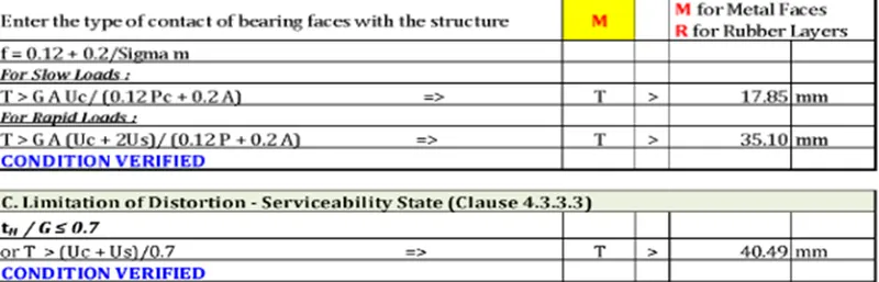
- Mean Pressure – SLS Case
σm = P/A’ <= 11MPa
Where P=Permanent + Variable load
A’= Area of bearing plate
The mean pressure on the bearing should be less than 11MPa
- No Slip condition – SLS Case
σm min = Pmin/A > 2MPa
The minimum pressure required for proper transmission of friction forces from superstructure to substructure via bearings is 2MPa due to permanent loads only.
B2. Horizontal force < Friction coefficient x Vertical Load
- Explain the differences between the minimum load cases & the maximum load cases in the design of bearings
Ans. The design of bearings is done for two load cases that is maximum and minimum.
Maximum reaction is summation of all the loading i.e. permanent and variable(dead load, sidl, live load, wind, seismic etc)
Minimum reaction is summation of permanent loading only i.e Dead load and SIDL, so as to know how the structure behaves without action of external loading.
- What are the other types of bearings used in a design of metro viaduct? Explain the locations where these are used. Conditions where elastomeric bearings used?
Ans. Sliding bearing consist of two metal plates, commonly stainless-steel plates, that slide relative to each other and hence makes room for translational movement and lubricating material between them as illustrated in Figure-1.
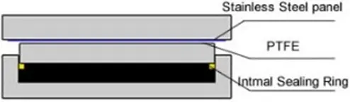
Fig.1: Sliding Bridge Bearing
It is specified by ASSHTO that sliding bearing cannot be used unless the bridge span is smaller than 15m. This is because sliding bearing cannot be purely used if the bridge experiences rotation movement. However, the span restriction for sliding bearing utilization can be disregarded when it is used in combination with other bearing types.
Rocker is an expansion bearing composed of curved surface at the bottom, which accommodate translational movement and a pin at the top makes room for rotation movement as illustrated Figure-2 and Figure-3 in detail.
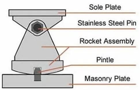
Fig.2: Rocker Bridge Bearing
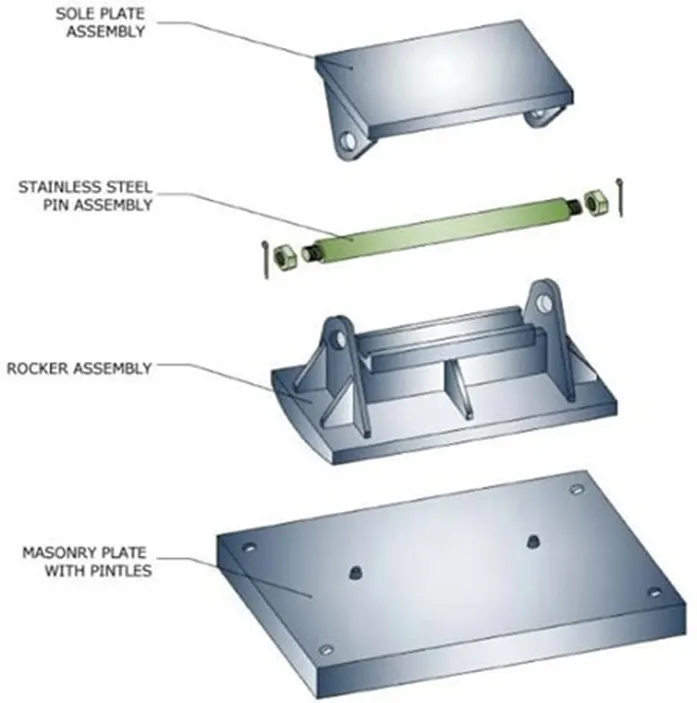
Fig.3: Rocker Bridge Bearing
Pin bearing is a fixed bearing that make room for rotation movement through the application of steel pin. It has similar structure and component like rocker bearing apart from the bottom of pin bearing which is flat and fixed to the concrete pier, as can be observed in Figure-4.
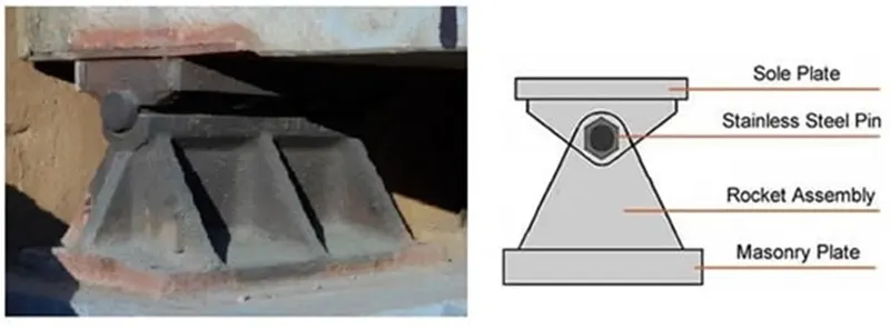
Fig.4: Pin Bearing for Bridges
Both rocker and pin bearings are mainly employed in steel bridge structure. Rocker and pin bearing should be considered when the bridge movement is adequately known and described, since such bearings can make rooms for both translational and rotational movements in one direction only. These bearings are likely to suffer deterioration and corrosion, so it is necessary to conduct regular inspection and maintenance.
Roller Bearings for Bridges
Roller bearing can be used in the construction of reinforced concrete and steel bridge structure. There are two main configurations including single roller bearing which is composed of one roller placed between two plates and multiple roller bearing that consist of several rollers installed between two plates. The former as shown in Figure-5 can accommodate both rotation and translation movement in longitudinal direction and it is cheap to manufacture but its vertical load capacity is limited. In contrary, the latter as shown in Figure-6 can make room for translation movement only and rotation movement can be accommodated if rollers are combined with pin bearing. Multiple roller bearings are expensive and support considerably large vertical loads. Regular inspection and rehabilitation should be conducted since roller bearing are susceptible to corrosion and damages.
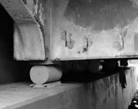
Fig.5: Single Roller Bridge Bearing
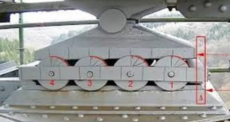
Fig.6: Multiple Roller Bridge Bearing
Elastomeric Bearings for Bridge Structures
It consists of elastomer manufactured from synthetic or natural rubber and can take both translation and rotation movements through elastomer deformation. The ability of elastomer to carry large vertical loads is because of reinforcement provision that prevents lateral bulging of elastomer. There are number of elastomeric bearing pads classified based on types of reinforcements used. For example, steel reinforced, plain, fiberglass reinforced and cotton duck reinforced elastomeric bearing pads. Strength and response of each type is different, steel reinforced elastomeric bearing is the strongest one and plain elastomeric pad is the weakest. Elastomeric bearing is neither expensive nor requires considerable maintenance, that is why it the most desired bearing type. Figure-7 show details of elastomeric bearing and its application in bridge structure.
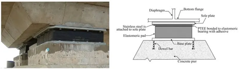
Fig.7: Elastomeric Bridge Bearing
Curved Bearings for Bridges
It consists of two curved plate that match each other as shown in Figure 8. If curved bearing is cylindrical, then it only accommodates rotation movements. However, both rotation and translational movements can be dealt with if curved bearing is spherical. Due to the fact that both gravity loads and curved geometry generate lateral resistance against and consequently lateral movement would be limited, that is why polytetrafluoroethylene (PTFE) slider is adhered to the bearings in order to make rooms for lateral movements. Details of curve bearings can be seen in Figure-8.
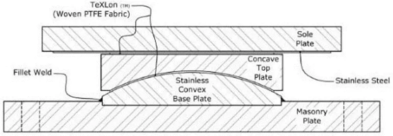
Fig.8: Spherical Bearing for Bridges
Pot Bearings for Bridge Structures
As shown in Figure-9, pot bearing consists of elastomeric disk confined in a pot, steel piston that is properly tailored into the pot wall and flat sealing rings which keeps elastomeric inside the pot. Pot bearing can support considerable vertical loads and it is commonly transferred through steel piston to the elastomeric disc which is almost incompressible. As far as lateral load is concerned, it is transferred as the steel pistol moves toward pot wall. Translational movement is limited in pure pot bearing that is why PTFE are introduced to the sliding surface to make rooms for translation movement.
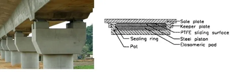
Fig.9: Pot Bridge Bearing
Disk Bearings for Bridges
Different components of disk bearing are shown in Figure-10 in detail. Rotation movement is accommodated through the deformation of elastomer whereas the translation movement is considered through the application of PTFE slider.
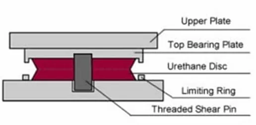
Fig.10: Disk Bearing
The utilized elastomer should be adequately hard to support vertical loads without suffering large deformations and sufficiently flexible to allow rotational movement. Both vertical loads and lateral loads are supported by elastomeric disk and metal ring in the center of the bearing respectively.
- Explain the load flow behavior in the design of prestressed pier caps with the relevant codal provisions.
Ans.
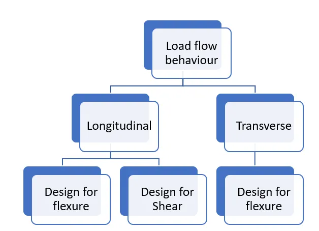
As we see in longitudinal direction of PSC pier cap it is to be designed for flexure and for shear, both will be taken by prestressed cables. In transverse direction as the wall is thin and since span is short, shear stirrups shall be avoided, the reinforcement shall be adequate enough to deal with the flexure and shear. If case comes of provision of shear r/f then we increase the thickness of the slab.
Other applicable codal provisions for design of prestressed pier caps will be for check of stresses and crack width which are as follows:
Ans.
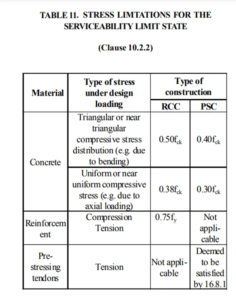
In RCC concrete with triangular distribution 0.5fck will only be at the top fibre and it will keep on reducing on inner fibres finally zero at neutral axis.
In uniform distribution average stress is calculated hence the value is reduced to 0.38fck which will be equally distributed to all fibres.
In PSC stresses limitations are less compared to RCC i.e. 0.4fck & 0.3fck which is observed during transfer of prestressing cable.
In prestress section we know that it has maximum compressive stress when external load is minimum and prestress has just been transferred to the section in that case we do not want to crush the section by applyin load immediately after prestressing. When external load of DL,SIDL,LL etc. comes into action, tensile stresses are taken by prestress tendons. So compressive & tensile stresses are negated. But during construction stage it cant be negated hence lesser stress limitaton is allowed for PSC.
For prestressing tendons, Immediately after anchoring the force in the prestressing tendon shall not exceed 70% of the characteristic strength for posttensioned tendons, or 75% for pre-tensioned tendons. The jacking force may be increased to 80% during stressing, provided that additional consideration is given to safety, to the stress- strain characteristics of the tendon, and to the assessment of the friction losses.
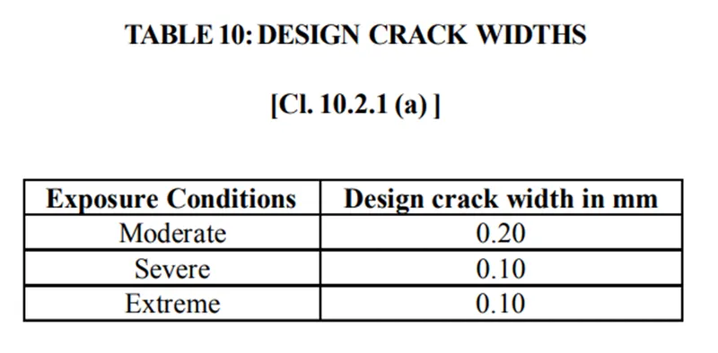
Moderate - Concrete surface protected against weather or aggressive conditions. Concrete surface sheltered from severe rain or freezing whilst wet. Concrete exposed to condensation, concrete structure continuously under water. Concrete in contact with non-aggressive soil/ground water.
Severe- Concrete surface exposed to severe rain, alternate wetting and drying or occasional freezing or severe condensation. Concrete exposed to aggressive sub-soil/ ground water or coastal environment.
Extreme - Concrete surface exposed to sea water spray, corrosive fumes or severe freezing conditions whilst wet. Concrete structure surfaces exposed to abrasive action, surfaces of members in tidal zone. All other exposure conditions which are adverse to exposure conditions covered above.
Based on the exposure conditions crack width limitations is decided.
It is assumed that human eye cannot see a crack of less than 0.3mm hence to keep a crack not visible is taken into consideration. Apart from it crack width create a room for corrosion of reinforcement, lesser the crack width lesser will be exposure of reinforcement.
- Why are PSC piers caps preferred over RCC pier caps in a metro viaduct?
Ans. In PSC the pier cap is already stressed to the maximum stress that will act on the structure, due to which the external stress that comes on the structure gets negated, leaving very minimum stress on the structure, hence crack width will also very minimum this increase the lifetime of the structure, whereas in RCC overtime the structure subjected to stress everyday develops crack and increases the risk. PSC is also light in weight compared to RCC. It can be easily placed on top of pier even if its precast, hence PSC pier caps are preferred over RCC pier caps.
- Explain the basic purpose of pier caps and the components of the pier caps with their uses.
Ans. Pier caps transfer the loads from the superstructure to the piers. They hold the bridge girders on bearing pads and disperse the loads from the bearings to the piers. Bridges with piers will all have pier caps to transfer the load from the superstructure.
Pier cap has a pedestal over it to support the bearing, it has holes for passing of drainage pipes