Challenge 5
Aim: To prepare and analyse a transverse model of Deck slab of PSC I girder using Staad Pro
Introduction:
- Slab laid on top of 4 I-girders.
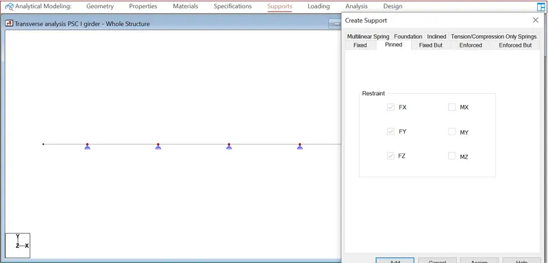
- Having supports spaced at 2.0m each.
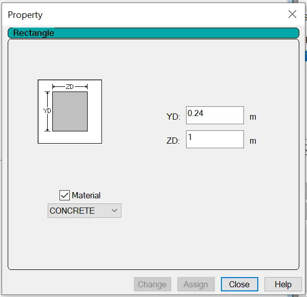
- Having following geometrical properties:
Thickness of slab = 0.240m
Width of slab = 1.0m
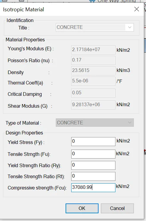
4. Having material properties: Concrete, M55 grade.
Procedure : Preparation of Staad model
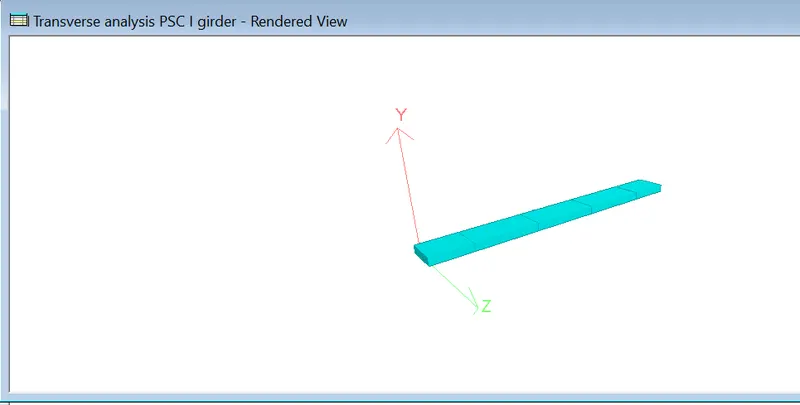
Create 1st node at 0,0,0 (X,Y,Z = Longitudinal, Vertical & Transverse)
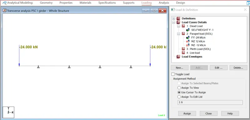
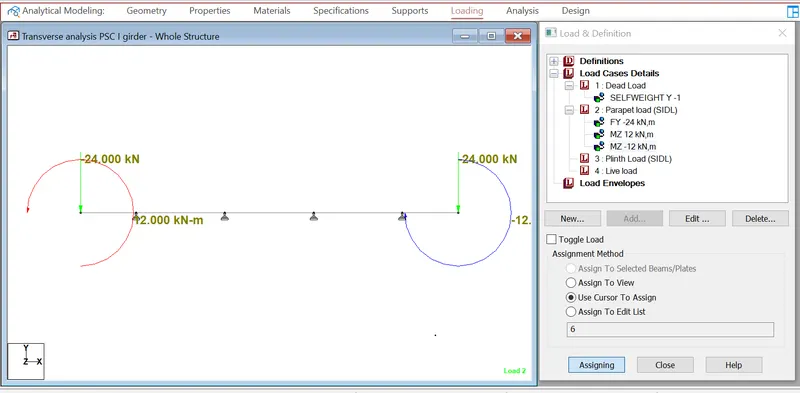
Considering overhang of 1.25m on both sides from end girder for parapet
And as per given data there are 4 I girders so there will be 4 supports for deck slab spaced at 2m
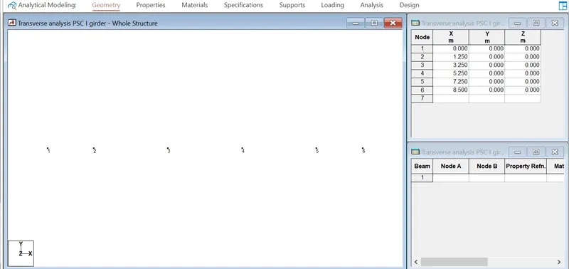
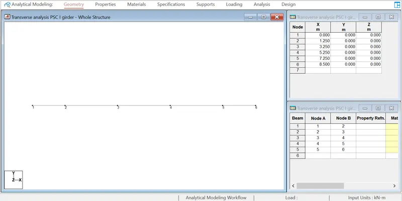
Now connecting the nodes by adding beam
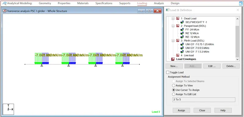
Live load
Max axle load = 16t = 160kN
Wheel load = 160/2 = 80kN
Applying this load on disperson length of 0.5m on each side of girder
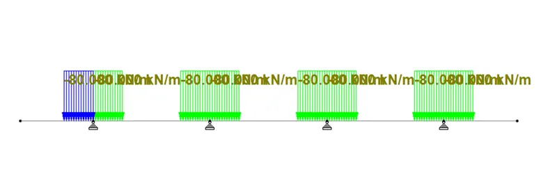
Now, prepare load combinations
Assume impact factor for live load = 1.25
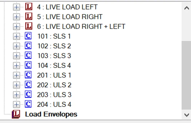
SLS 1 = DL+1.2SIDL
SLS 2 = DL+1.2SIDL+(1.1*1.25)LL
ULS 1 = 1.25DL+2SIDL
ULS 2 = 1.25DL+2SIDL+(1.75*1.25)LL
Cases can be created for live load to be running one time in left track and one time in right track, derailment load etc.
Results
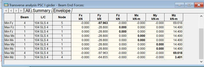
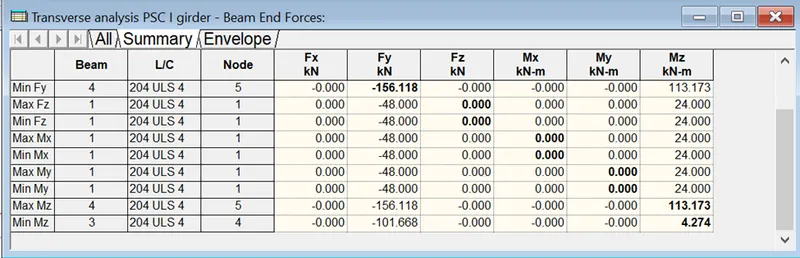
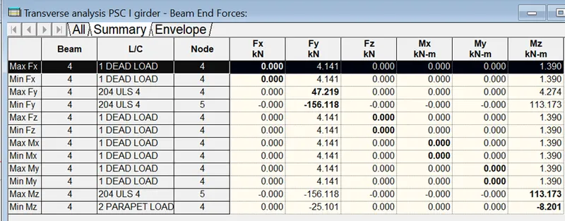
Reinforcement is designed for the maximum moment.
5) Explain the situations where mid diaphragms are provided in a viaduct.
Ans.The application of intermediate diaphragms in concrete girders may improve impact resistance and thus survivability of bridges. The reinforced concrete intermediate diaphragms are usually provided to help minimize impact damage and improve the impact resistance of prestressed concrete bridge girders. Reinforced concrete intermediate diaphragms provide more protection for the girders than that by the structural steel ones, when the lateral impact load is applied at the location of the intermediate diaphragm; whereas there is no apparent difference in impact resistance of two types of the intermediate diaphragms if the impact load is applied away from the diaphragm location. Green, et al. (2004) studied the contribution of intermediate diaphragms in enhancing the precast bridge girder performance, and their results indicated that intermediate diaphragms have a modest positive effect of reducing the maximum deflections for the chosen girder. the diaphragm increases bridge resistance in the case of accidental lateral loading, and also stabilises the girders during construction
6) Explain the STAAD procedure for design of diaphragm how the results are extracted and explain the formula for hogging & sagging moment of the metro viaduct.
Ans. Staad model of week 4 i.e PSC I girder longitudinal analysis model is considered for design of diaphragm
- Grillage model of 4 I-girders with span length of 27.0m.
- Having supports at 0.700m from both ends.
- Having following geometrical properties:
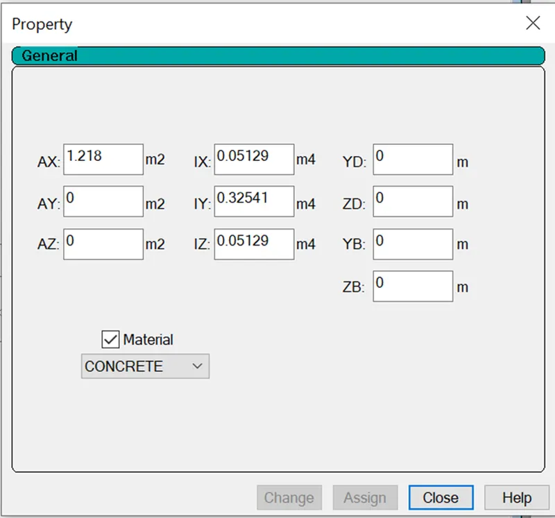
End Section: Area = 1.218m2
Iy = 0.32541m4
Iz = 0.05129m4
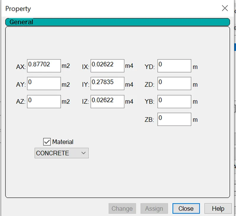
Mid Section: Area = 0.87702m2
Iy = 0.27835m4
Iz = 0.02622m4
- Having material properties: Concrete, M60 grade
Others data's are assumed
Procedure: Preparation of Staad model
Open Staad pro and create 1st node at 0,0,0 (X,Y,Z = Longitudinal,Vertical,Transverse)
Since the support is at 0.7m from both ends, nodes are created as at respective nodes and last node at 27m as span length is 27m
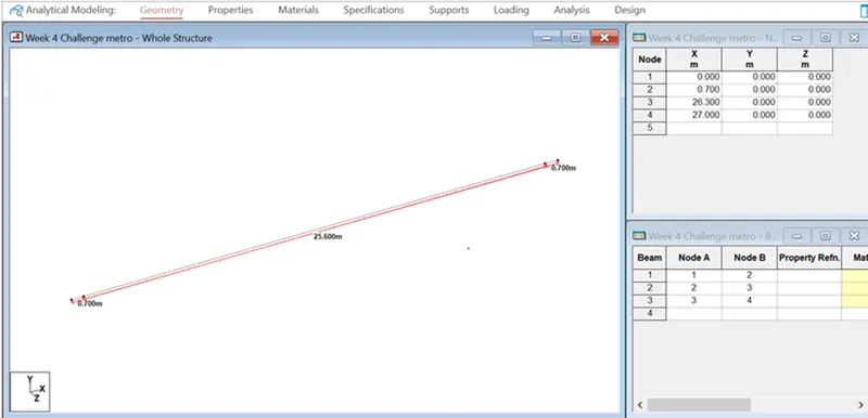
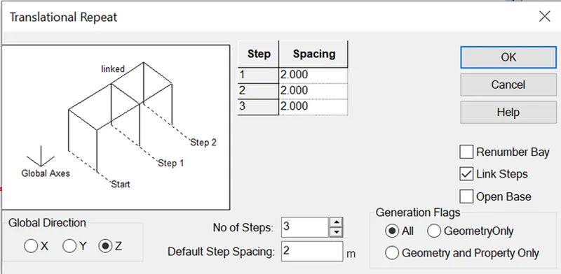
Now for creating 4girders translation repeat is used in Z direction
c/c spacing of girder = 2m(assumed)
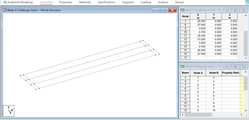
Now we create internal diaphragms at 2m distance in X direction
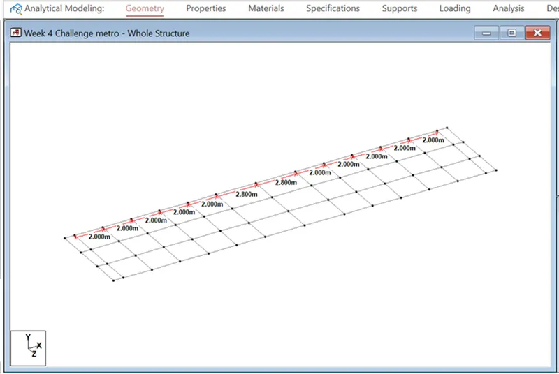
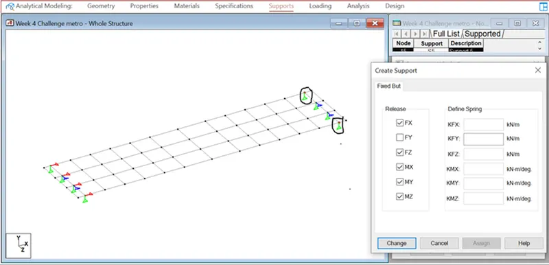
Now lets assign supports
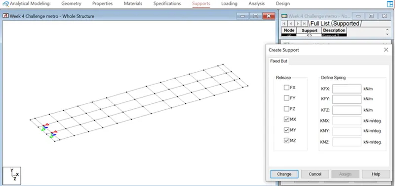
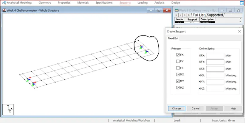
To allow longitudinal movement we release FX in next support
To allow transverse movement we release FZ in next support
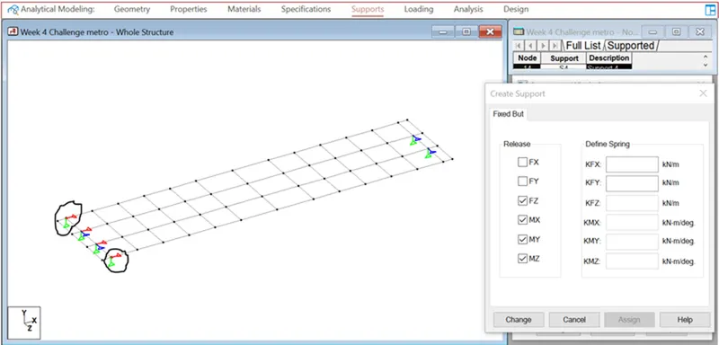
Now assigning roller support for free movement in X-Z plane
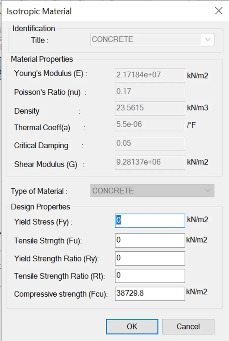
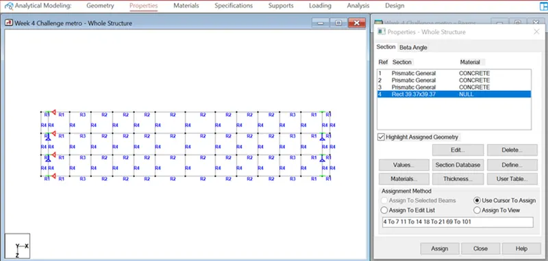
Now creating properties of the girder and diaphragm
Concrete is of M60, therefore compressive strength = 5000(fck)^0.5 = 5000(60)^0.5= 38729.83 MPa
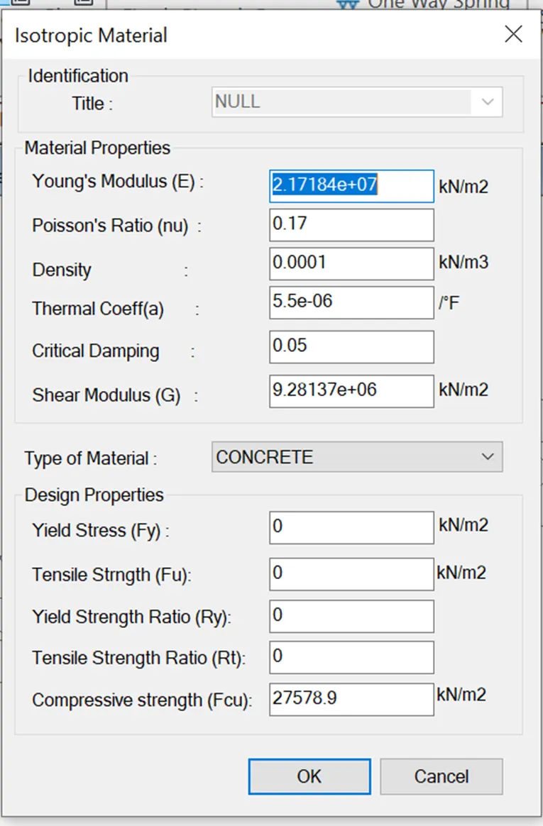
Creating Null property for diaphragms as these are to be modelled for as only connecting members and not of structural importance
End Girder property
Mid girder property
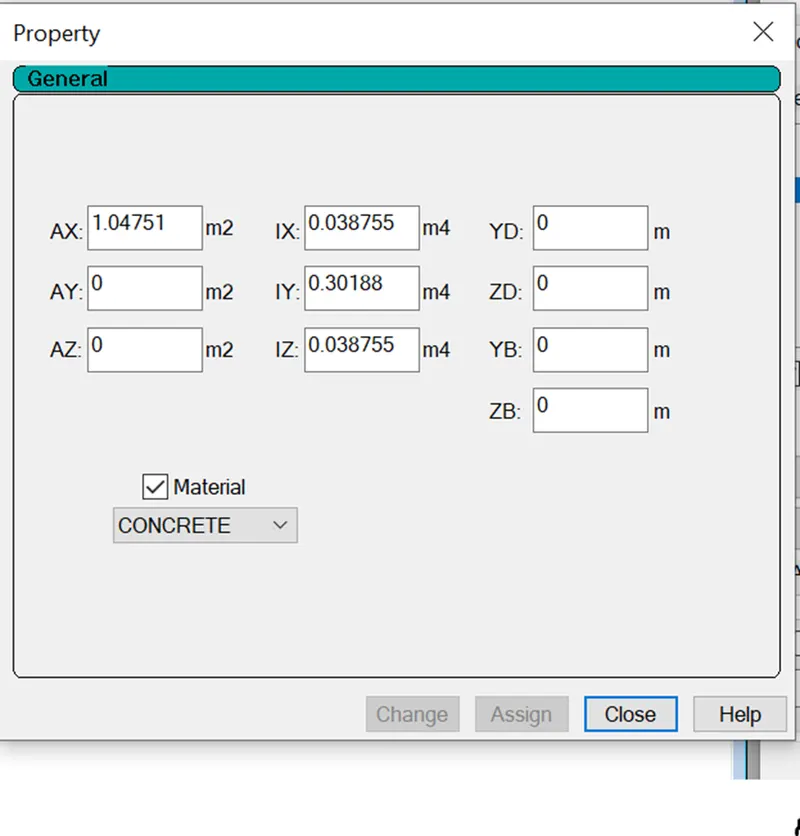
Tapering section property b/w end and mid girder(Average of both)
Diaphragm property
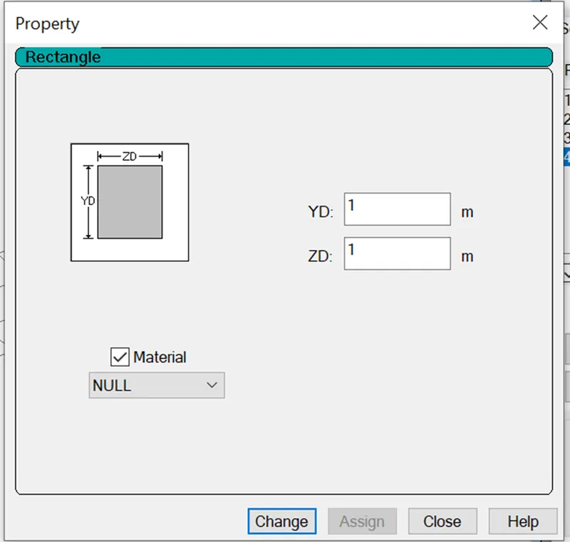
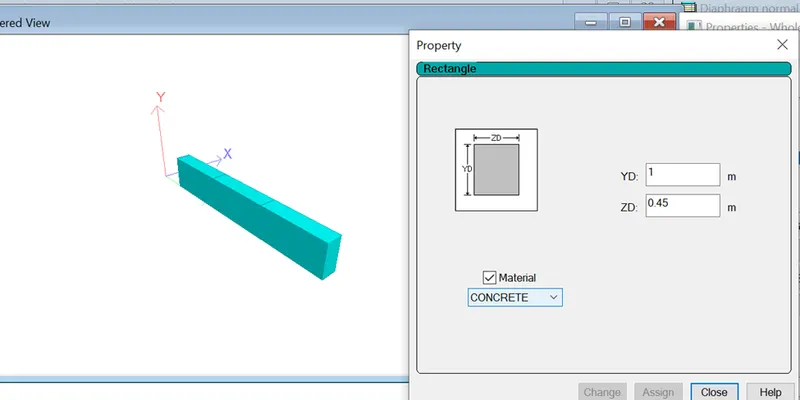
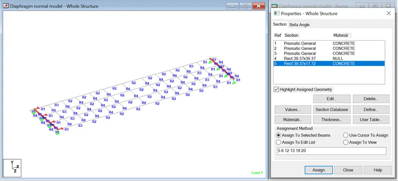
Now here we consider end diaphragms as 0.45m thick.
DEAD LOAD
It is assigned as self weight with factor Y -1 as we have given properties to the girder.
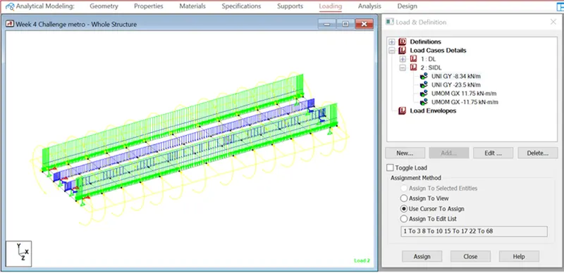
SIDL
Applied as 8.34kN/m - Load of plinth/deck, rails & rail pad
23.5 kN/m - Load of parapet
As parapet is in end, we take into consideration moment generated due to parapet - Cg of parapet = 0.5m Therefore moment = 23.5*0.5=11.75kNm
For Live Load we first define vehicle of metro, since span is 27m we define 2 bogies
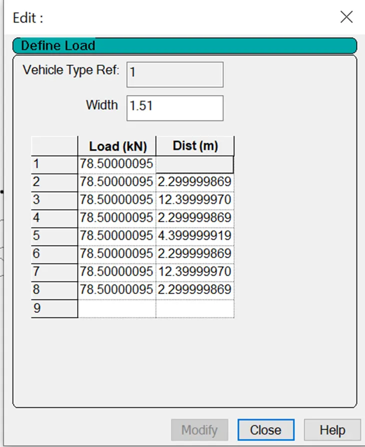
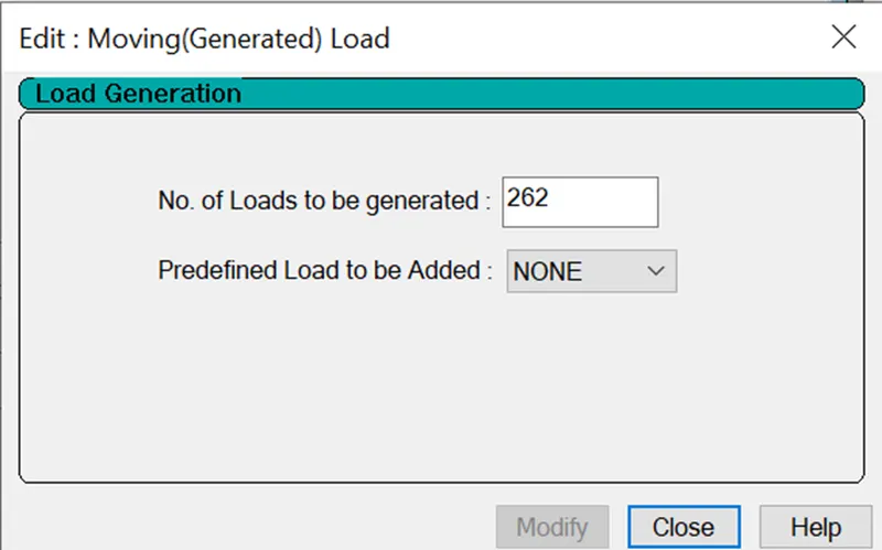
Now generating moving load
No.of Load generations = (Length of vehicle + Length of span) /increment = (2.3+12.4+2.3+4.4+2.3+12.4+2.3 + 27)/0.25=261.2
Two trains are running one on left side and one on right side
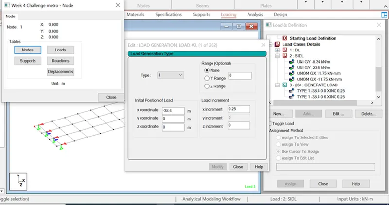
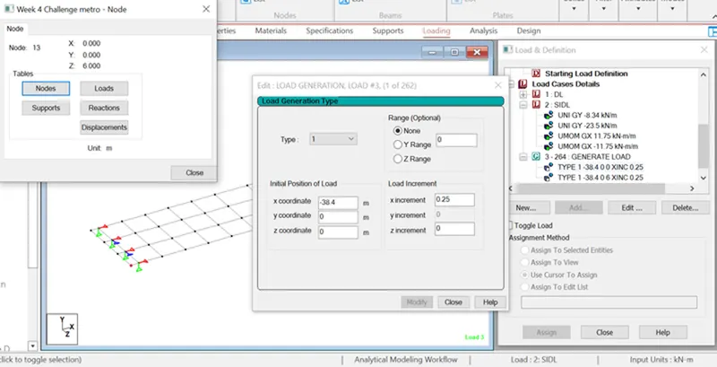
Now run analysis
After analyzing lets check which beam of diaphragm has maximum moment
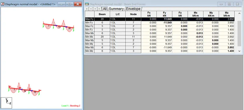
For DL beam 20&6
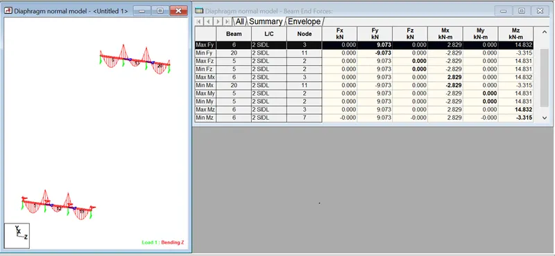
For SIDL Beam 6
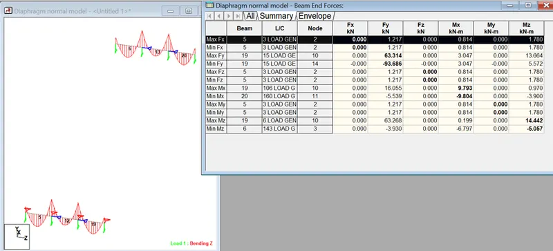
For Live Load beam 19
Since maximum Fz is for SIDL & DL at beam 6 so we extract section forces for beam 6
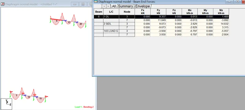
SLS Load combination
DL+1.2SIDL+1.1LL*Impact
Impact factor = 1+0.15(8/(6+L)*0.72=1+0.15(8/(6+25)*0.72=1.29
As we have 2 tracks impact factor shall be reduced by 0.72 as per IRS bridge rules clause.2.4.1.1
SLS Moment Hogging(+ve) = 1.4+1.2*14.8+1.1*(-5.057)*1.29=11.98kNm
SLS Moment Sagging (-ve)=3.892+1.2*(-3.315)+1.1*2.804*1.29=3.89kNm
Reinforcement is checked for these moment using software
7)Where jacks can be placed for lifting the sections under the diaphragm. Also, what is the distance between the center of the girder to center of the jacks.
Ans. Jacking is done when we replace bearing after its lifetime. So we support the structure from end diaphragms at both ends between the girders. Generally the distance of jacks from the girder is 0.65m.
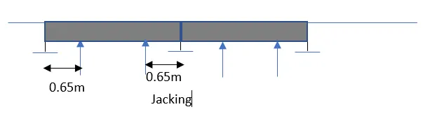
8)Prepare a line model for jacking case, considering the distance between the center of the girder to center of the jacks as 650mm & other inputs mentioned in the video session.
Ans. 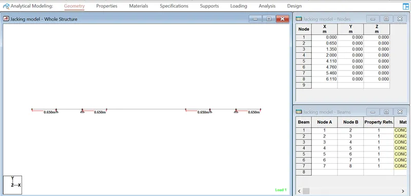
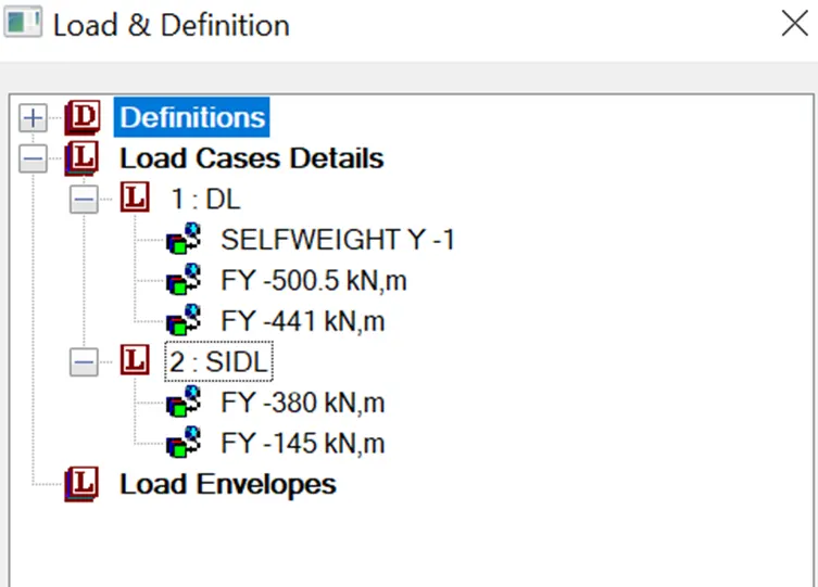
9)As a result of moment extraction & sectional check, what are the values we attain to check that our design is safe.
Ans. Hogging moment, Sagging moment, Allowable Fc, Allowable Fs and Allowable crack width are the values we get to check our design.