Challenge 4 : Concept Modelling of Alloy Wheel
1.Title of the Project:
- Surfaces for Alloy Wheel.
2.Objective:
- To build the Surfaces for Alloy Wheel uisng Canvas image.
3.Introduction:
- In this Autodesk Alias is a family of Computer-aided industrial design (CAID) software predominantly used in Automotive Design and Industrial Design for generating Class A surfaces using Bezier surface and NURBS modeling method.
- We are using this to Design to build the Surface Using the Alloy Wheel Traced from the given Image of Alloy Wheel.
4.Design Methodology / Approach:(To be explained with the help of Flowcharts only)
- Using Autodesk Alias 2020 Software, to build the surface using the curves model.
- Using New Page to create and Import that Canvas Image Front View, Top View, Side View, Back View.
- Alignment that Canvas Image size On Using Scale tool and Create New layers Option to seperate the layer.
- Using the Curve Tools in Palette Tool Box Option to New CV curve Tool to trace that model image.
- Using Circle and Ellipse in Keypoint curve Toolbox to drow the model.
- Using Detach Tool to separate the curves and surface area.
- Extend tool to using endpoint of surface to extending the surface and projecting area and trim it out unwanted area
- Using Symmetry to trace the curves plane.
- Using Blend Curve Create tool to creating the edge to perfect curve.
- Using spans and Degree to Adjust the curve line to trace the image model.
- And Using Surface option to create the shape for model by surface tool.
- Set Planar Tool to creating the surface to given the curve for alloy wheel.
- And Creating Curves line to trim that un wanted surface to remove it.
- Using Project / Intersect tool to projecting the curve line to the surface area.
- Using trim / Untrim Tool to using trimming area.
- Checking the surface continuity tool to whether the surface plane are in continuity line.
- Surface Option using that Skin Tool is using that controlling that curve are in continuity.
- Controlling the surfae area continuity by the Free Boundary, G0 Position, G1 Tangent, G2 Curvature, Implied Tangent, Implied Curvature, Tangent Angle.
- Using freefrom blend Tool to controlling the continuity by using position, curvature, Tangent.
- Using Align Tool to merge the both surface to continuity.
- Using Birail Gen 1 Surface Tool to creating surface area.
- And Using the Diagonstic shade to View the model of the image.
5.Description (Need to explain tools/ Features used while designing) along with the images of Part files.
- Curves (New CV Curve Tool) : Creating NURBS Curves in the scene by placing CVs.
- Keypoint Curve Tool : Using Circle and Ellipse to create two major axis point to create curves.
- Blend Curve Create Tool : Let You Create and Edit blend curves in the scene by placing location constraints
- Blend Curve Edit Tool : Let You Edit the Blend direction and continuity point.
- Extend : Curve Lines can be Extended to that paticular area.
- Detech Tool : Separate a curve or surface two or more object.
- Align Tool : Align a curves or surface edge to another curve or surface edge.
- Layers : Layers can be Assign that image to hide and mark and Pick to use.
- Degree And Spans : using this type to control that curves line to alinment that shape to trace that image.
- Surface Control : The Continuity Table displays one row for each boundary curve involved in the Square operation.
- Project : Project is that surface of the image can be project any curves in that surface area.
- Trim : Trim option is used to be remove unwanted surface area by projecting tool.
- Duplicate Curve Tool : Duplicate any curve that are picked when you click the tool and any curves while the tool is active.
- Surface Continuity Tool : Checks The positional, Tangent plane and curvature continuity between and inside surface.
- Diagonstic Shade : This tool can be giving that shape for texture and Colour for that model.
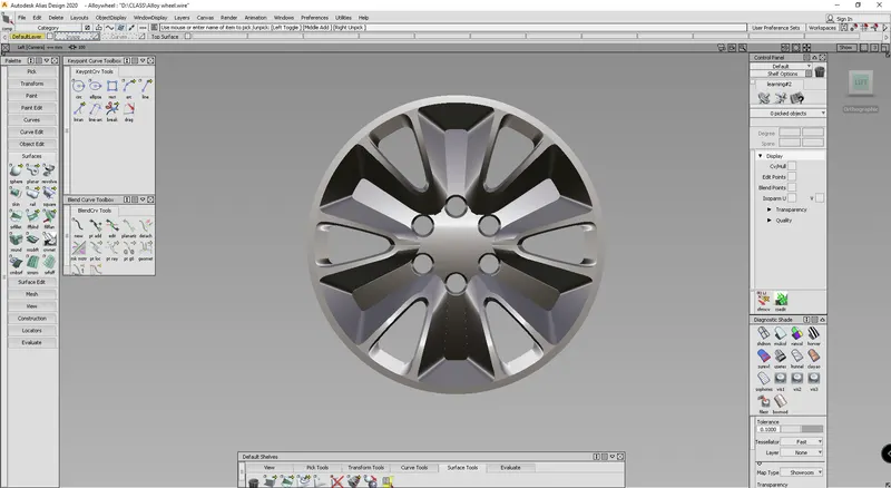
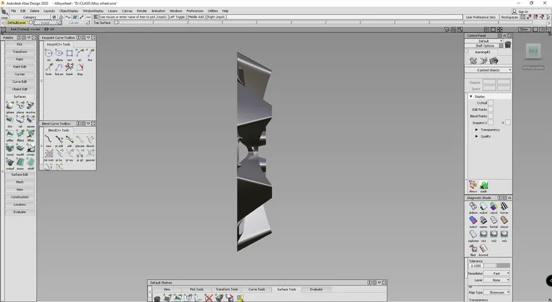
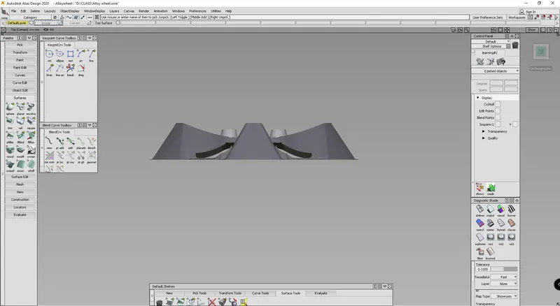
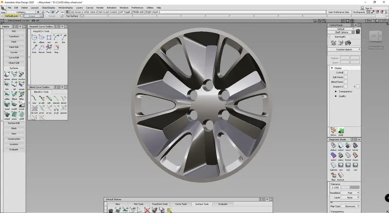
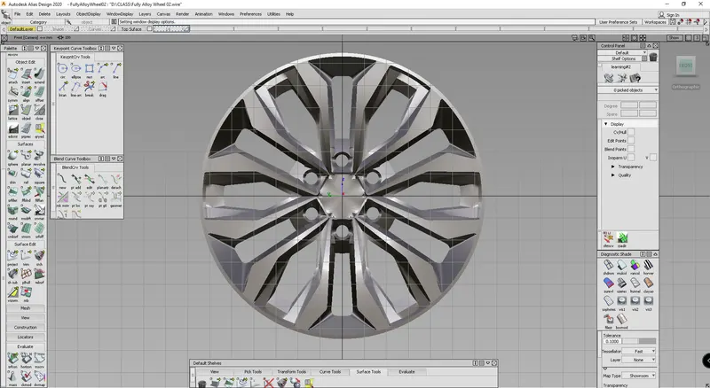
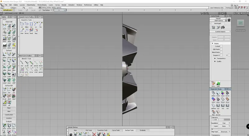
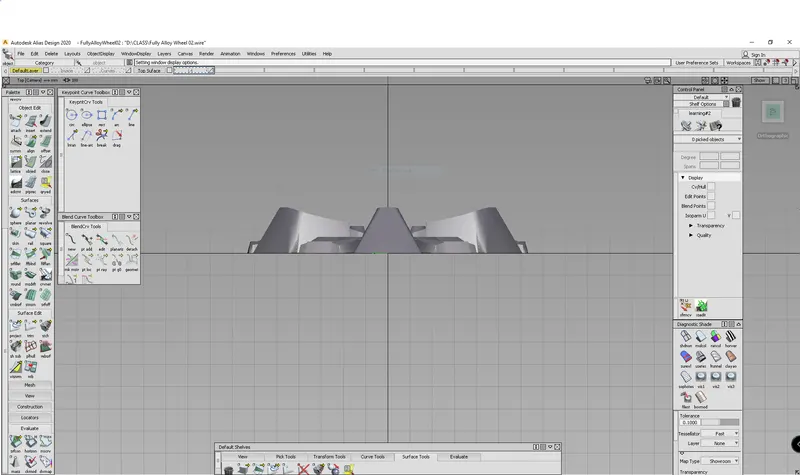
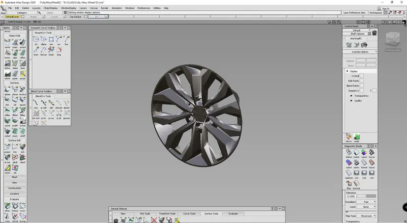
6.Upload a min of 4 screenshots of Model in the report. (For eg:-Front View, Side View, Isometric View and the Top View)
Assignment 1:
Assignment 2 :
7.Conclusion :
- On Overall The technique of overbuilding surfaces, align surface with continuity check and then intersecting and trimming them can be used to create detailed design.