Challenge 2
Aim :
1) What are the structural components of a bridge? Explain in detail about the foundation, sub structure and super structure components of the bridge
2) What is Super Imposed Dead Load means? What are loads that needs to be considered as SIDL for a metro viaduct bridge?
3) What are the different types of girders that can be used for a metro viaduct?
4) What are bearings in a metro viaduct. Explain the types of bearings and analyses the types with respect to their advantages and disadvantages
5) During the construction of metro viaducts across water passages, explain the topographical check list that needs to be considered for the designing the height of the viaducts?
6) What are the different types of girders that can be used in a metro viaduct construction? Explain the differences of the girders and elucidate how a designer has to choose his girder type whilst designing.
7) Explain why the choice of metro designers would be precast U girders in India.
8) What is an open web structure? Brief the advantages of the system.
9) Explain the load flow behavior in a open web girder.
10) As per IRS CBC, Table 11(Clause 10.2.2) the stress limitations of SLS, Explain your understanding of the table and how it correlated while designing a viaduct for metro rail construction.
11) Explain your understanding of crack widths. Brief the three different design crack width with respect to IRS CBC
Introduction:
The given questions summarize the type of superstructure substructure and bearings in a elevated metro project along with its design aspects like loadings and design checks based on ULS and SLS combinations.
Procedure:
1) What are the structural components of a bridge? Explain in detail about the foundation, sub structure and super structure components of the bridge
Ans. The structural components of a bridge are its superstructure which carries the load and then substructure which transfers the load of superstructure to the foundation and foundation then transfers the load to the ground below.
Foundation-The bridge foundation are particularly essential or critical since they ought to maintain the entire load of the bridge and the traffic loads that it will pass on. A bridge foundation is the part built under the pier or abutment and over the fundamental soil or rock. The loads sent by the foundations to the subordinate soil should not cause soil shear failure or harming settlement of the superstructure. Reason for foundation is to convey the load of bridge over an enormous bearing region and give solidness of bridge against settlement and shifting. It is given adequately profound with the goal that it not influenced by the scouring.
The foundation of a bridge relies upon nature and profundity. There are few types of bridge foundation that are built.
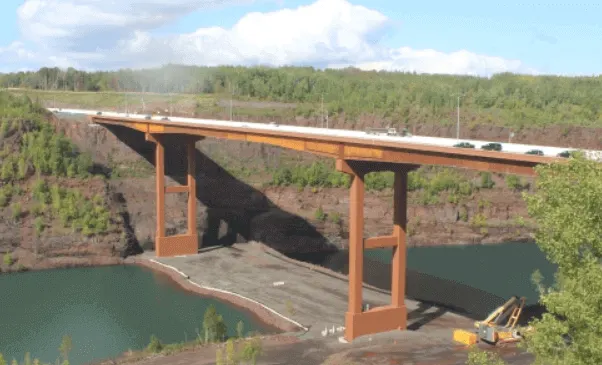
1. Spread Foundation
The spread foundation is additionally called an open foundation and is reasonable for bridge foundation of normal tallness based on a firm and dry ground to offer help for the construction. This types of bridge foundation is appropriate where there is least scouring and the hard grounds starts from 1.5m – 3m underneath the level of the watercourse.
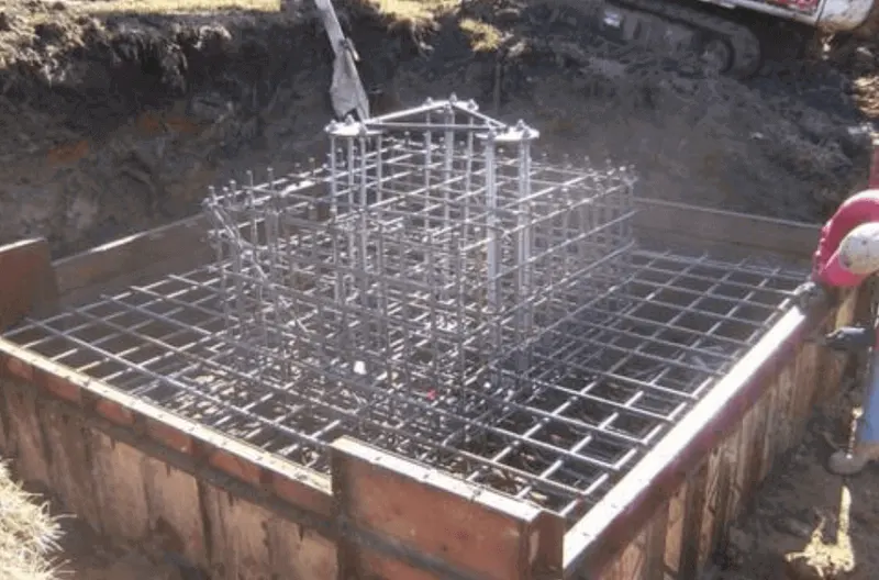
2. Raft Foundation
These types of bridge foundation are generally utilized where there passable bearing limit of the soil is less and the watercourse bed contains delicate clay and silt. It favors foundations where hard soil isn’t found inside sensible profundity of 1.5m – 2.5m, beneath the watercourse.
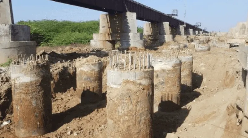
3. Pile Foundation Bridge
Pile foundation is the types of bridge foundation that is utilized in conditions where there is extremely delicate soil and hard strata are not accessible at a sensible profundity. It is likewise utilized where scouring of a river as to be done and a enormous concentrated load is to be taken by the foundation.
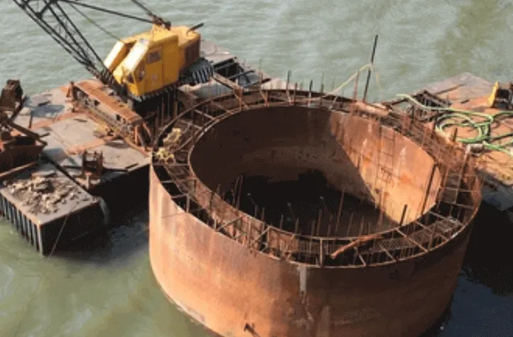
4. Well Foundation Bridge
Well foundation of bridge is the types of bridge foundation that is utilized when the bed has sandy soil also, hard soil is accessible at 3 – 4 m beneath the level of the watercourse. Most appropriate on soil a cotton having delicate soils what’s moresandy soils and weighty scouring is relied upon due to the huge velocity of approach of the river.
5. Caisson Bridge Foundation
Caisson foundation is a types of bridge foundation that is utilized where there is a hard layer close to the river bed and there is exorbitant water profundity that isn’t monetarily strong to eliminate the empower sinking wells for well foundation.
6. Grillage Foundation
This types of bridge foundation is reasonable for weighty and separated footings of wharfs where deep foundations are to be stayed away from. Grillage foundation is most appropriate where sub soil conditions are poor.
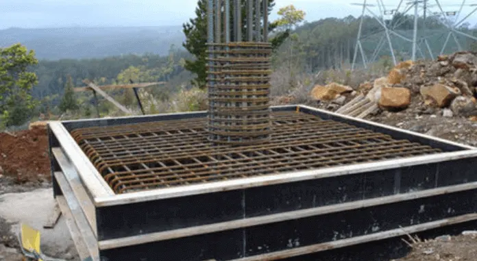
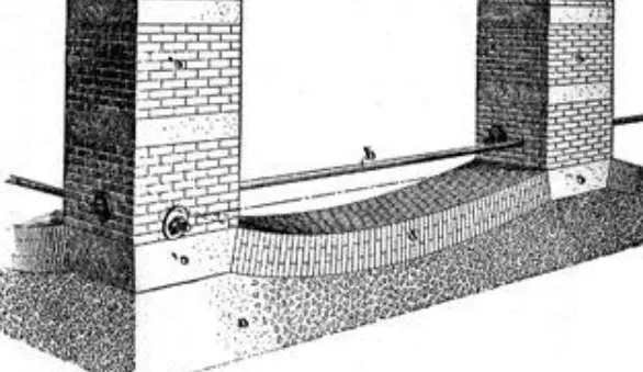
7. Inverted Arc Foundation
This types of bridge foundation is appropriate when the profundity of unearthing for foundation is less. Inverted arc foundation is most appropriate where the bearing limit of the soil is less, particularly when the sub soil has some delicate pockets and there is plausibility of inconsistent settlement.
Superstructure components
It consists of the following.
Beams and girders
Both have a similar function to support the roadway and prevent bending. Girder is also one type of beam support. Where loads are heavy girders are used instead of beam support.
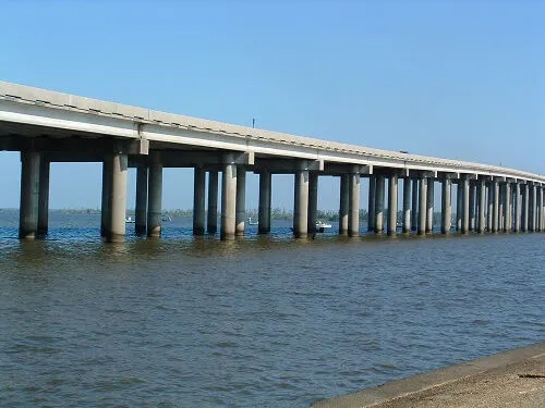
Beam has a rectangle cross-section, whereas girders have composed of I-shaped cross–sections with two load-bearing flanges and a web for stabilization.
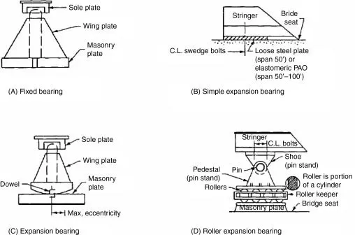
Bearing
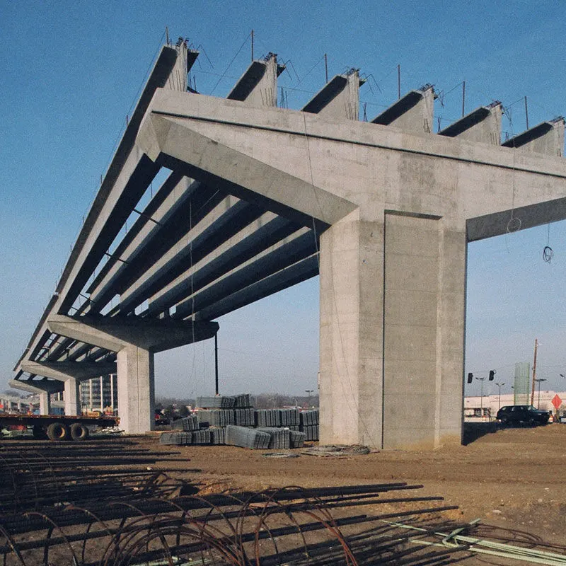
A bearing is provided between the bridge girder and the pier cap. The main function of the bearing to allow free movement or vibration of the top superstructure and reduce effect stress to reach the bridge foundation.
Arch and Cables
Arched and Cable both have specified used. Arches are used for arch bridge construction and cable is used for suspension, cable-stayed bridges, etc. For different types of bridge construction arches and cables play a vital role.
Parapet Wall and Handrail
The parapet is one of the safety components of any bridge which prevent the vehicle from falling off where there is a drop.
It is also useful for restricting views, preventing rubbish from passing below, and acting as a noise barrier.
Flooring
Its top surface of bridge roadway on vehicle travel. It is made of concrete or a bituminous road.
Substructure Components
The components involved in substructure of bridges are:
- Piers & Pier cap
- Abutments
- Wing Walls and the Return wall
Piers & Pier cap
The superstructure transfers its load through piercap to pier with the help of bearings. piers are vertical structures used to support deck or the bearings provided for load transmission to underground soil through foundation. These structures serve as supports for the bridge spans at intermediate points.
The pier structure has mainly two functions:
- Load transmission to the Foundation
- Resistance to the horizontal forces
Most of the cases, piers are designed to resist the vertical loads alone. In areas which lie in the seismic zone, it is recommended to design the pier for lateral loads also.
Most of the piers are constructed using concrete. Steel for the construction of pier is used in very few cases till now. Use of composite columns i.e. steel columns filled with concrete is used as new technology of pier construction.
The pier is a vertical member that resist the forces by means of shear mechanism. These forces are mainly lateral forces. The pier that consist of multiple columns are called as bent.
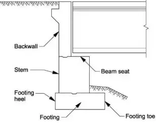
Abutments are vertical structures used to retain the earth behind the structure. The dead and the live loads from the bridge superstructure is supported by the bridge abutments.
The abutments are also subjected to lateral pressures mainly from the approach embankment. The design loads on the abutment is mainly dependent on the:
Type of abutment selected
The sequence of construction
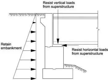
As seen from the above figure, the abutments have the design requirements similar to retaining walls as well as in pier construction. The abutments are primarily designed to resists the overturning and sliding. More focus is on the stability of the whole system
 0
0
Wing Walls and Returns
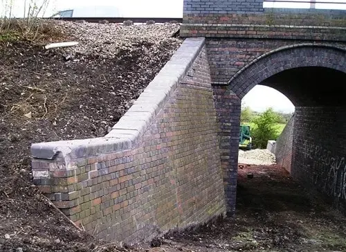
Structures constructed as an extension of the abutments to retain the earth present in the approach bank are called wing walls. This portion will otherwise have a natural angle of repose. These are retaining walls constructed adjacent to the abutments. This wall can be constructed either integrally or independent with the abutment wall.
The rear of the wall must consider three design loads while designing. This includes:
The earth pressure from the backfill
The surcharge from the live loads or the compacting plant
The hydraulic loads from the saturated soil conditions
The stability of the wing wall is mainly based on its resistance against the active earth pressures. The structural elements of the bridges are hereby designed and constructed to resist the earth pressures at rest.
2) What is Super Imposed Dead Load means? What are loads that needs to be considered as SIDL for a metro viaduct bridge?
Ans. Super Imposed Dead load means permanent load carried by the structure but not of structural importance with respect to design aspect I.e. it does not provides structural strength.
Loads to be considered as SIDL for metro viaduct bridge are:
Track structure
Cable trays, cable trough & Cables
Parapet structure
Rails, fasteners
OHE mast, signaling equipment etc.
3) What are the different types of girders that can be used for a metro viaduct?
Ans. Different types of girders that can be used for a metro viaduct are as follows:
Precast concrete is a form of concrete that is prepared, cast and cured off-site, usually in a controlled factory environment, using reusable moulds. Precast concrete elements can be joined to other elements to form a complete structure. It is typically used for structural components such as; wall panels, beams, columns, floors, staircases, pipes, tunnels, and so on.
Structural steel frames can provide an alternative for pre-fabricated structural components, but precast concrete can be more economical and sometimes more practical. Many buildings now include a mixture of both construction techniques, sometimes incorporating structural steelwork, in-situ concrete and precast concrete elements.
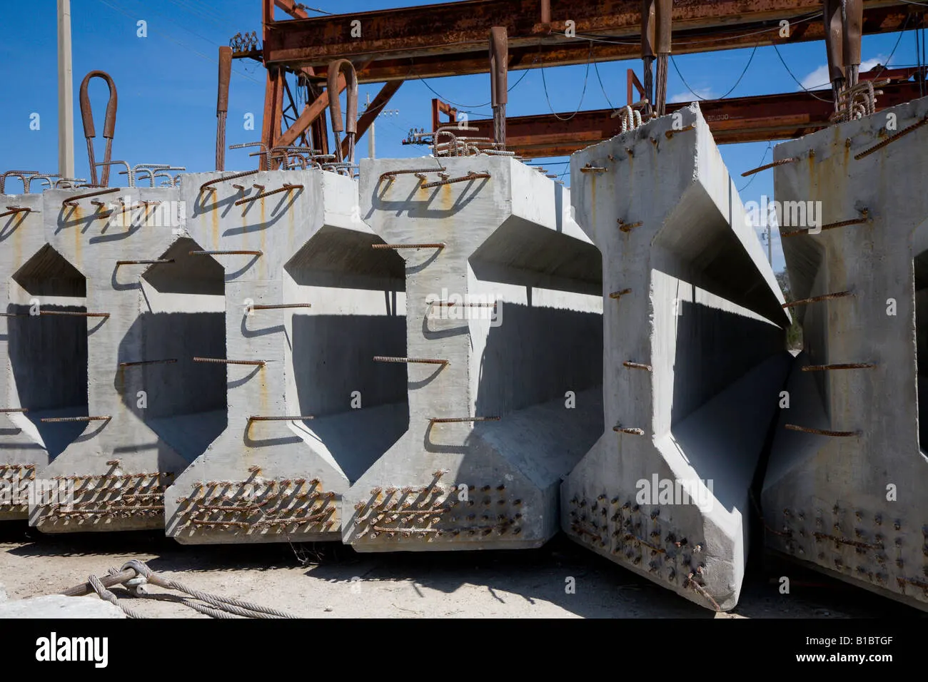
1- Precast prestressed I girder
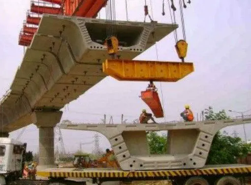
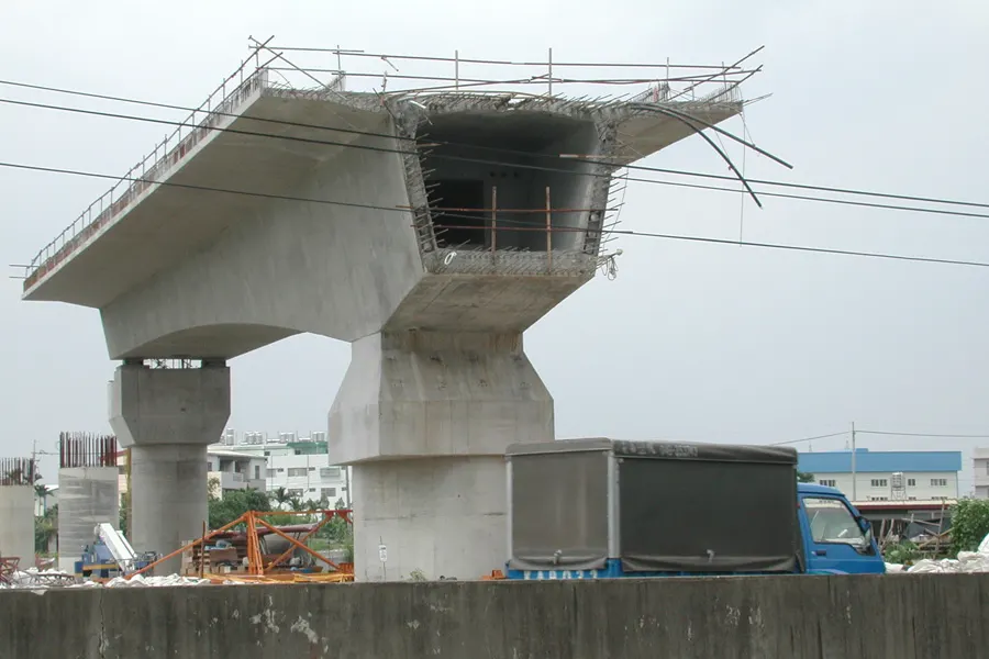
2- Precast prestressed box girder( full span/ segmental)
Segmental
Full span
3- Precast pretensioned U girder
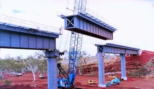
4- Steel plate girder
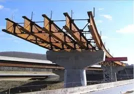
5- Steel box girder
6- Steel truss
4) What are bearings in a metro viaduct. Explain the types of bearings and analyses the types with respect to their advantages and disadvantages
Ans. Bridge bearings are structural equipment or devices installed between bridge substructure and superstructure to transfer the applied load including earthquake loads; wind loads; traffic loads; and superstructure self-weight.
Bridge bearings also makes rooms for relative movements between superstructure and substructure, for instance, rotation movements and translational movements in horizontal and transverse direction.
Bearing used in the construction of bridge structure is divided into two major categories namely expansion bearings and fixed bearings. The former permits both translational and rotational movements whereas the latter allow rotational and limited translational movements.
There are several types of bridge bearings which have been employed in bridge construction which are discussed below.
Sliding bearings
Rocker and pin bearings
Roller bearings
Elastomeric bearings
Curved bearings
Pot bearings
Disk bearings
Sliding Bearings for Bridges
Sliding bearing consist of two metal plates, commonly stainless-steel plates, that slide relative to each other and hence makes room for translational movement and lubricating material between them as illustrated in Figure-1.
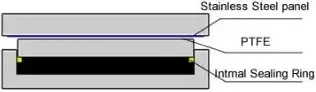
Fig.1: Sliding Bridge Bearing
A friction force is generated in sliding bearing and it is imposed on substructure, superstructure and sliding bearing itself. So, it may be required to provide lubricant such as polytetrafluoroethylene (PTFE) to decline generated friction.
It is specified by ASSHTO that sliding bearing cannot be used unless the bridge span is smaller than 15m. This is because sliding bearing cannot be purely used if the bridge experiences rotation movement.
However, the span restriction for sliding bearing utilization can be disregarded when it is used in combination with other bearing types.
Rocker and Pin Bearings for Bridge Structures
Rocker is an expansion bearing composed of curved surface at the bottom, which accommodate translational movement and a pin at the top makes room for rotation movement as illustrated Figure-2 and Figure-3
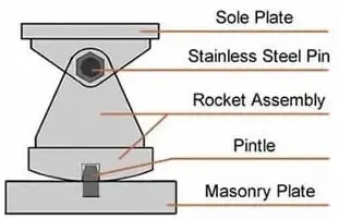
Fig.2: Rocker Bridge Bearing
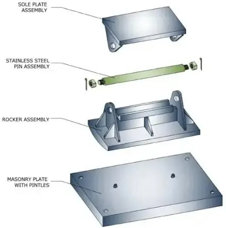
Fig.3: Rocker Bridge Bearing
Pin bearing is a fixed bearing that make room for rotation movement through the application of steel pin. It has similar structure and component like rocker bearing apart from the bottom of pin bearing which is flat and fixed to the concrete pier, as can be observed in Figure-4.
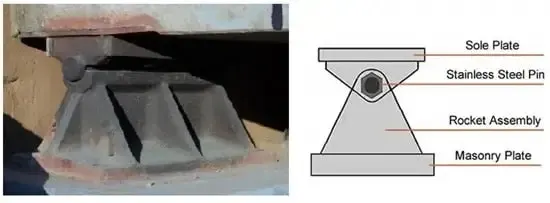
Fig.4: Pin Bearing for Bridges
Both rocker and pin bearings are mainly employed in steel bridge structure. Rocker and pin bearing should be considered when the bridge movement is adequately known and described, since such bearings can make rooms for both translational and rotational movements in one direction only.
These bearings are likely to suffer deterioration and corrosion, so it is necessary to conduct regular inspection and maintenance.
Roller Bearings for Bridges
Roller bearing can be used in the construction of reinforced concrete and steel bridge structure. There are two main configurations including single roller bearing which is composed of one roller placed between two plates and multiple roller bearing that consist of several rollers installed between two plates.
The former as shown in Figure-5 can accommodate both rotation and translation movement in longitudinal direction and it is cheap to manufacture but its vertical load capacity is limited.
In contrary, the latter as shown in Figure-6 can make room for translation movement only and rotation movement can be accommodated if rollers are combined with pin bearing. Multiple roller bearings are expensive and support considerably large vertical loads.
Regular inspection and rehabilitation should be conducted since roller bearing are susceptible to corrosion and damages.
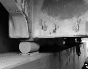
Fig.5: Single Roller Bridge Bearing
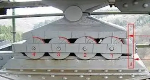
Fig.6: Multiple Roller Bridge Bearing
Elastomeric Bearings for Bridge Structures
It consists of elastomer manufactured from synthetic or natural rubber and can take both translation and rotation movements through elastomer deformation. The ability of elastomer to carry large vertical loads is because of reinforcement provision that prevents lateral bulging of elastomer.
There are number of elastomeric bearing pads classified based on types of reinforcements used. For example, steel reinforced, plain, fiberglass reinforced and cotton duck reinforced elastomeric bearing pads.
Strength and response of each type is different, steel reinforced elastomeric bearing is the strongest one and plain elastomeric pad is the weakest.
Elastomeric bearing is neither expensive nor requires considerable maintenance, that is why it the most desired bearing type. Figure-7 show details of elastomeric bearing and its application in bridge structure.
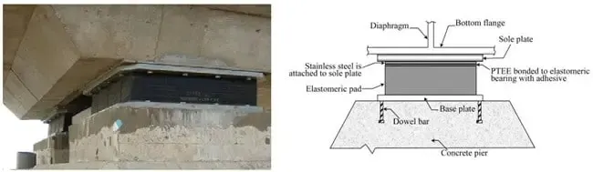
Fig.7: Elastomeric Bridge Bearing
Curved Bearings for Bridges
It consists of two curved plate that match each other as shown in Figure 8. If curved bearing is cylindrical, then it only accommodates rotation movements. However, both rotation and translational movements can be dealt with if curved bearing is spherical.
Due to the fact that both gravity loads and curved geometry generate lateral resistance against and consequently lateral movement would be limited, that is why polytetrafluoroethylene (PTFE) slider is adhered to the bearings in order to make rooms for lateral movements. Details of curve bearings can be seen in Figure-8.
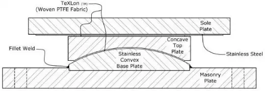
Fig.8: Spherical Bearing for Bridges
Pot Bearings for Bridge Structures
As shown in Figure-9, pot bearing consists of elastomeric disk confined in a pot, steel piston that is properly tailored into the pot wall and flat sealing rings which keeps elastomeric inside the pot.
Pot bearing can support considerable vertical loads and it is commonly transferred through steel piston to the elastomeric disc which is almost incompressible. As far as lateral load is concerned, it is transferred as the steel pistol moves toward pot wall.
Translational movement is limited in pure pot bearing that is why PTFE are introduced to the sliding surface to make rooms for translation movement.
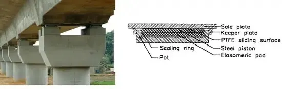
Fig.9: Pot Bridge Bearing
Disk Bearings for Bridges
Different components of disk bearing are shown in Figure-10 in detail. Rotation movement is accommodated through the deformation of elastomer whereas the translation movement is considered through the application of PTFE slider.
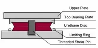
Fig.10: Disk Bearing
The utilized elastomer should be adequately hard to support vertical loads without suffering large deformations and sufficiently flexible to allow rotational movement.
Both vertical loads and lateral loads are supported by elastomeric disk and metal ring in the center of the bearing respectively.
5) During the construction of metro viaducts across water passages, explain the topographical check list that needs to be considered for the designing the height of the viaducts?
Ans. During the construction of metro viaducts across water passages, the topographical checklists are:
High flood level (HFL)of the watercourse,
Bed level of the waterbed,
Width of waterway,
Discharge of the watercourse.
Superstructure bearing level if kept above free board of the river HFL which is obtained by average of high water level of previous years data available so that in future the traffic of the bridge is not disturbed at any cost.
Foundation base is laid below the bed level of the river so that the load is transferred properly below the bed
In this way depending on the bed level and HFL height of substructure can be determined.
6) What are the different types of girders that can be used in a metro viaduct construction? Explain the differences of the girders and elucidate how a designer has to choose his girder type whilst designing.
Ans.
1- Precast prestressed I girder
This can be used when having loading is to be taken and economy is not an issue for the client, No.of I girders can be laid parallely to support the deck for structures not having much of torsion.
2- Precast prestressed box girder( full span/ segmental)
This is also one of the commonly used girders in which level of rail or road has to be elevated a bit more. The shear due to torsion has a full path along the periphery of the wall to travel so we get more area for torsion. Hence when case arises of high torsion this type of girders are used. For short spans single span of box girder is prepared and launched whereas for long spans it is divided into segments of 2-3m and joint during launching.
3- Precast pretensioned U girder
This girder is lighter in weight compared to box girder, it is feasible for torsion for spans lesser than 30m.Since trains run at bottom deck, side walls of girder apart from acting as structural element aslo will act as parapet so separate parapet need not be constructed and it also acts as noise barrier.Since it's light weight seismic force also reduces for design. it can be launched also easily.
4- Steel plate girder/ box girder
Everytime 30m span will not be feasible as the site of construction might have topographical restrication of obstruction like a railway line or a river way. So for spans above 30m to 60-70m steel girder can be used as it is easy to construct and launch because of its light weight much of cost of concrete is saved.
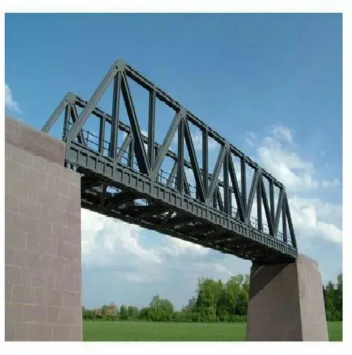
6- Steel truss
For spans more tham 60-70m truss type of arrangement is done.
For spans more than 100m balanced cantilever technique method is done for construction.
7) Explain why the choice of metro designers would be precast U girders in India.
Ans. In majority countries most popular choice for metro elevated bridge would be precast pretensioned U girders for the following reasons:
- It is a precast member so it has a better quality control
- It is a open section hence can be built on a single go and can be easily launched on piers.
- It is a slender section, also light weight therefore foundation size gets optimized thereby saving the economy.
- Since it's light weight seismic force also reduces for design.
- Since it is a open web section, Rails will be at lower level compared to box section due to which height of vehicle can be increased and hence height of station can be reduced compared to box section thereby saving cost of pier section.
- The top portion of open web has a deck at top which acts as a floor for people to enter train hence separate flooring cost is reduced.
- Since trains run at bottom deck, side walls of girder apart from acting as structural element aslo will act as parapet so separate parapet need not be constructed and it also acts as noise barrier.
- As it I'd light weight it can be erected also easily and need not be divided into segments.
8) What is an open web structure? Brief the advantages of the system.
Ans. Open web girder is a structure which is partially vacant in web part.
To overcome transverse force some portion of web part is removed for shear and torsion stability.
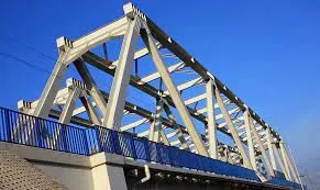
Advantages of the open web structure are:
- It is a open section hence can be built on a single go and can be easily launched on piers.
- It is a slender section, also light weight therefore foundation size gets optimized thereby saving the economy.
- Since it's light weight seismic force also reduces for design.
- Since it is a open web section & light weight it can be built for large spans thereby reducing the number of piers and reducing cost ofpier, piercap & foundation.
- As it is open cost of maintenance is also reduced.
- As it I'd light weight it can be erected also easily and need not be divided into segments.
9) Explain the load flow behavior in a open web girder.
Ans.
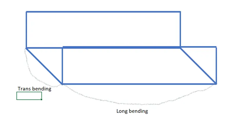
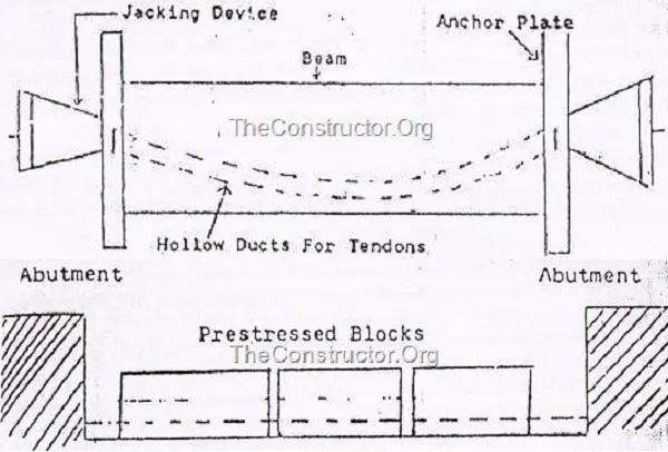
The U shape girder on application of load will bend in longitudinal & Transverse direction. Hence we need to design for both the direction.
In longitudinal direction it has to be design for flexure as well as shear, whereas in transverse direction due to short span it has to be design for flexure only shear will not have much effect.
In logitudinal direction prestressing tendons will take all the load and in transverse direction reinforcement will take all the load so respectively design must be done by preparing separate models for each direction.
10) As per IRS CBC, Table 11(Clause 10.2.2) the stress limitations of SLS, Explain your understanding of the table and how it correlated while designing a viaduct for metro rail construction.
Ans.
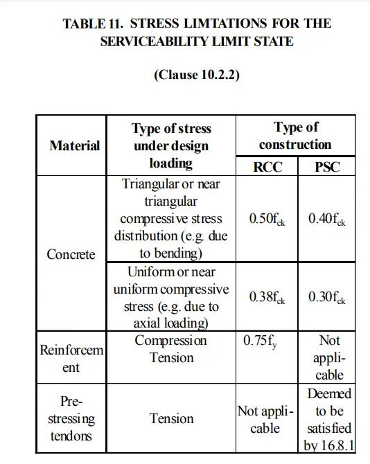
In RCC concrete with triangular distribution 0.5fck will only be at the top fibre and it will keep on reducing on inner fibres finally zero at neutral axis.
In uniform distribution average stress is calculated hence the value is reduced to 0.38fck which will be equally distributed to all fibres.
In PSC stresses limitations are less compared to RCC i.e. 0.4fck & 0.3fck which is observed during transfer of prestressing cable.
In prestress section we know that it has maximum compressive stress when external load is minimum and prestress has just been transferred to the section in that case we do not want to crush the section by applyin load immediately after prestressing. When external load of DL,SIDL,LL etc. comes into action, tensile stresses are taken by prestress tendons. So compressive & tensile stresses are negated. But during construction stage it cant be negated hence lesser stress limitaton is allowed for PSC.
For prestressing tendons, Immediately after anchoring the force in the prestressing tendon shall not exceed 70% of the characteristic strength for posttensioned tendons, or 75% for pre-tensioned tendons. The jacking force may be increased to 80% during stressing, provided that additional consideration is given to safety, to the stress- strain characteristics of the tendon, and to the assessment of the friction losses.
11) Explain your understanding of crack widths. Brief the three different design crack width with respect to IRS CBC.
Ans.
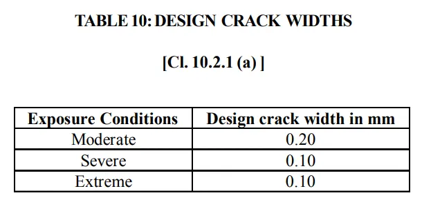
Moderate - Concrete surface protected against weather or aggressive conditions. Concrete surface sheltered from severe rain or freezing whilst wet. Concrete exposed to condensation, concrete structure continuously under water. Concrete in contact with non-aggressive soil/ground water.
Severe- Concrete surface exposed to severe rain, alternate wetting and drying or occasional freezing or severe condensation. Concrete exposed to aggressive sub-soil/ ground water or coastal environment.
Extreme - Concrete surface exposed to sea water spray, corrosive fumes or severe freezing conditions whilst wet. Concrete structure surfaces exposed to abrasive action, surfaces of members in tidal zone. All other exposure conditions which are adverse to exposure conditions covered above.
Based on the exposure conditions crack width limitations is decided.
It is assumed that human eye cannot see a crack of less than 0.3mm hence to keep a crack not visible is taken into consideration. Apart from it crack width create a room for corrosion of reinforcement, lesser the crack width lesser will be exposure of reinforcement.