CFD analysis of flow over NACA 0017 airfoil at different angles of attack
In this project, simulation of flow over NACA 0017 airfoil is performed using Flow Simulations add in of Solidworks.
To generate the co-ordinates of NACA 0017, the following data was fed into NACA 4 digit generator of airfoiltools.com
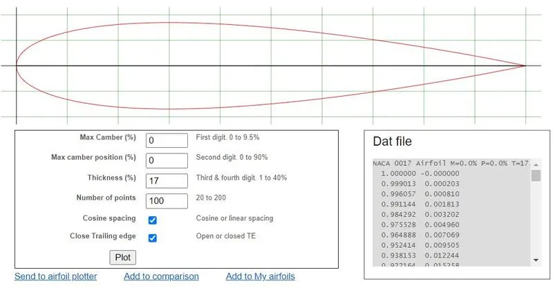
These co-ordinates were copied into a text file, a column with all rows zero was added to represent the z co-ordinates. The text file was then used to generate the airfoil shape in Solidworks.
A 2D external flow simulation was set up in Solidworks with initial velocity, V_x = 600 m/s.
The computational domain size was choosen as:
Upstream direction (-x) = 5c
Downstream direction (+x) = 15c
Y-direction = 10c
where c is the chord length of the airfoil, here c = 1m
The domain is shown below: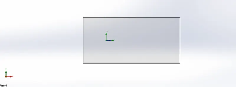
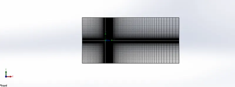
Now, for the meshing automatic meshing feature was used with refining level = 3. A local mesh was also added near the airfoil surface with refining level = 3.
The angle of attack (AoA) was varied from 0 - 10 degrees in steps of 2.
On performing the simulations, the following results are obtained:
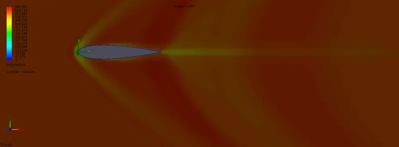
1. AoA = 0 degree
2. AoA = 2 degree
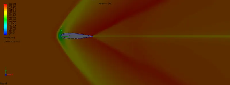
3. AoA = 4 degree
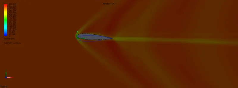
4. AoA = 6 degree
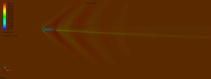
5. AoA = 8 degree
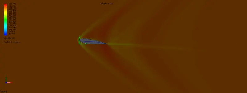
6. AoA = 10 degree
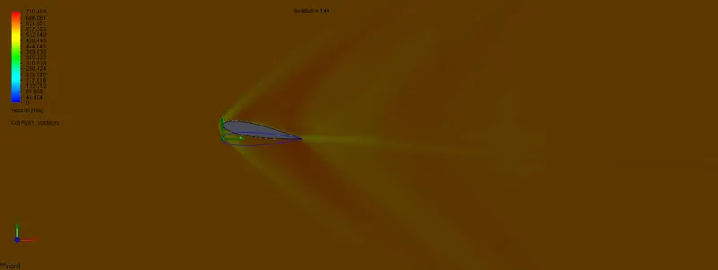
The above plots show the velocity contours for the different AoA. We can see how the airfoil affects the flow domain. Moreover, we can also see how the AoA changes the flow structure. Due to the different flow structure for different AoA, we get different lift and drag forces for different AoAs.
We can also see that due to the symmetry of the airfoil, the velocity contour is symmetrical for the 0 degree AoA case. The lift force, thus, comes out to be negative in this case.
The variation of drag force with angle of attack is shown below: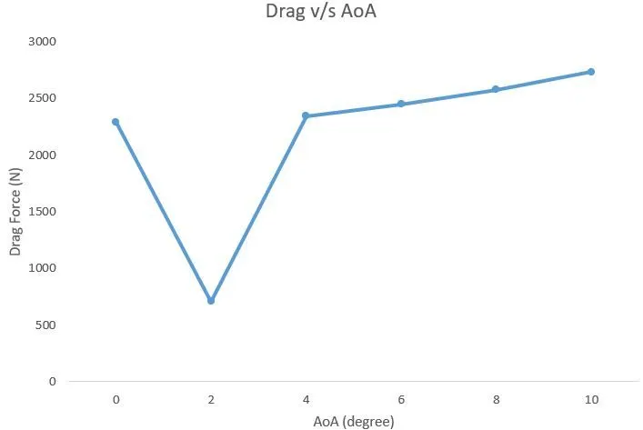
So, we can see that as the angle of attack increases the drag force on the airfoil increase except for a dip in the plot. This can be due to the complex wake structure behind the flow
The variation of lift force with angle of attack is shown below: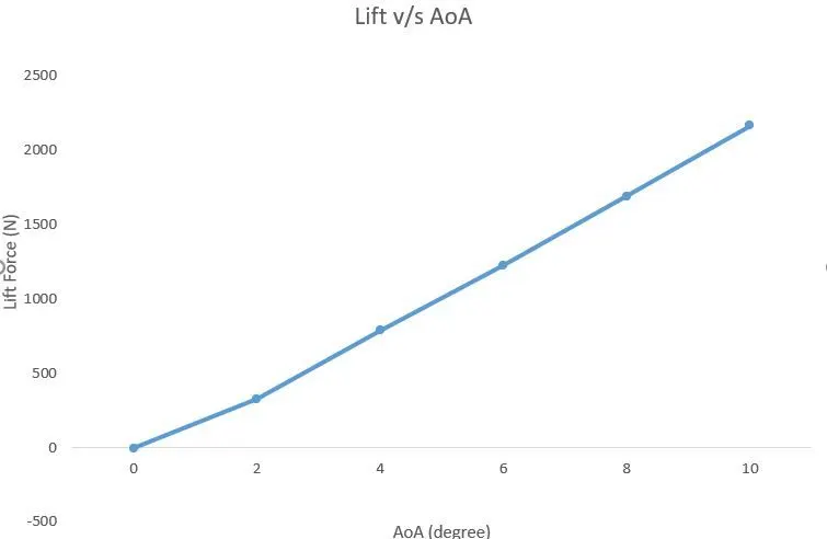
We can see that the lift force increases with the angle of attack and no dip is yet achieved. This means that the stalling condition has not yet reached. The increase of lift can be attributed to the flow separation and the wake structure behind the airfoil.