Centrifugal pump design and analysis
Aim: In this study, i show the relationship between the mass flow rate and pressure ratio of centrifugal pump. This simulation study is done in solidworks software.
Introduction: A centrifugal pump is a mechanical device designed to move a fluid by means of the transfer of rotational energy from one or more driven rotors, called impeller. Rotating of impeller causes the fluid rotation and by it fluid feel of centrifugal force
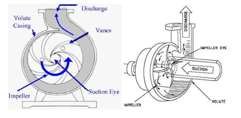
Methodology:
- Create the model of centrifugal component (a) Impeller
(b) Casing
(c) Virtual rotating flow region
(To check the flow trajectory)
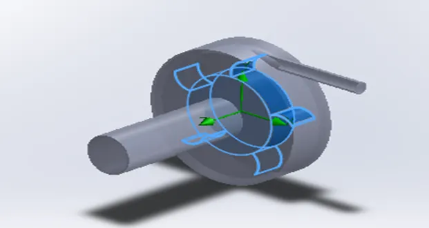
Centrifugal pump
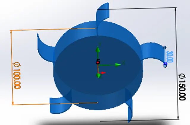
Impeller
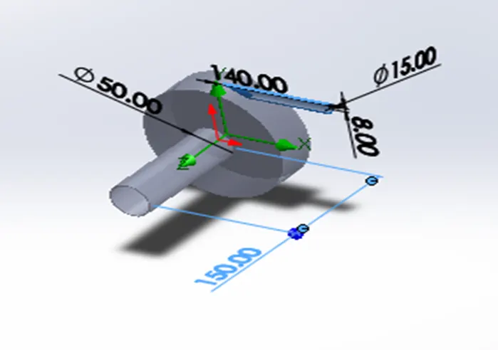
Casing
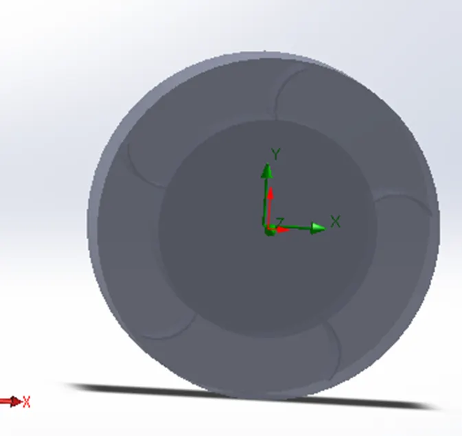
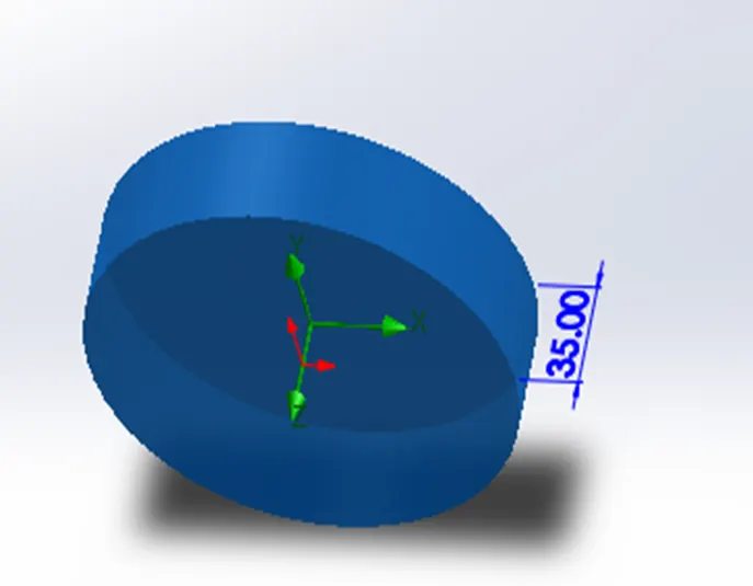
Rotating region
- Input the boundary condition be selecting the wizard tool of flow simulation and select also rotating region option.
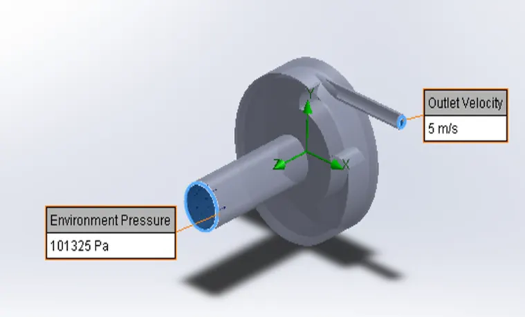
- Now i select the surface goal of average pressure(p2) (at outlet velocity condition) which is lid 2 area and mass flow rate at same location of lid 2 and also average pressure(p1) at lid 1 position which is environmental pressure area position. And create equation goal of ( pressure ratio=p2/p1)
- Run the simulation up to 500 iteration by controlling input condition option.
Result and Discussion:
Results after processing the parametric study
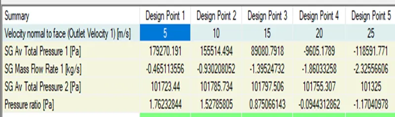
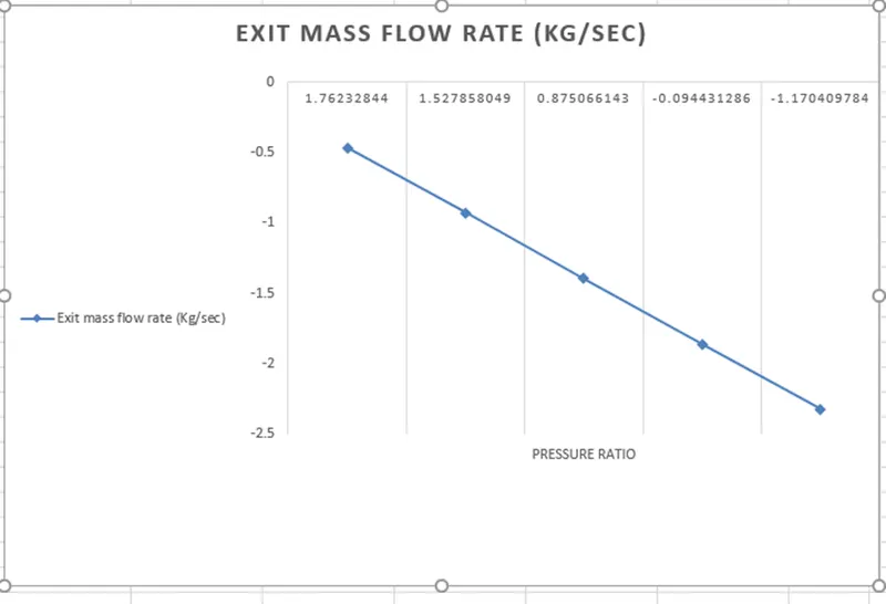
We can see in graph that by decreasing the pressure ratio mass flow rate increases because by decreasing the pressure ratio velocity at exit increases and velocity is function of mass flow rate.