Centrifugal pump design and analysis
Aim :
Perform flow simulation on centrifugal pump and analyze flow trajectories and relation beteen outlet velocity and pressure while keeping inlet same.
Introduction :
Centrifugal Pumps are most commonly used in industrial as well as Domestic applications for the transfer of fluids from one place to another place. Centrifugal pump works on the principle of centrifugal force i.e. if a force is acting away from the center of the circle called a Centrifugal force. Similarly, as the lifting of the liquid is due to the centrifugal action, these pumps are called centrifugal pumps. It works on the principle of forced vortex flow. The forced vortex flow means when a certain mass of fluid or liquid is allowed to rotate by an external torque than there is a rise in pressure head of the rotating liquid takes place. This rise in pressure head is used to deliver water from one location to another. It is centrifugal force acting on the fluid that makes it to flow within the casing.
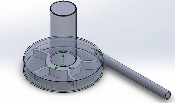
3D Model : (Dimesions chosen arbitrarily)
Study Setup :
Units : SI
Fluid : Water
Type : Internal Flow
Boundary Conditions : Inlet - Environmental Pressure ; Outlet Velocity - 10 m/s ; Rotating region - 1000 rad/s
For parametric study, input parameter is outlet velocity ranging from 10-30 m/s with 6 discrete values (10,14,18,22,26,30)
Results :
Base Simulation :
Velocity -

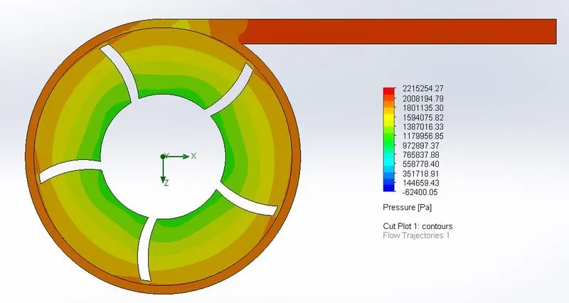
Pressure -
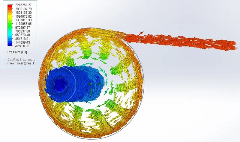
Flow Trajectories -
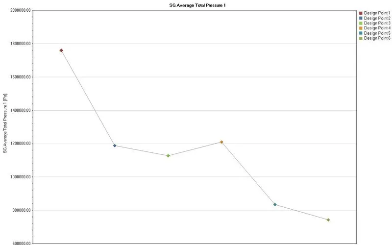
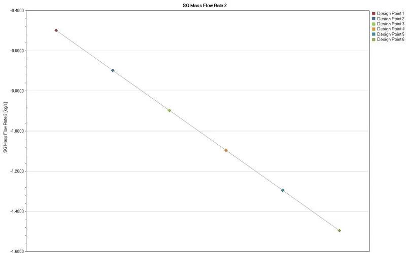
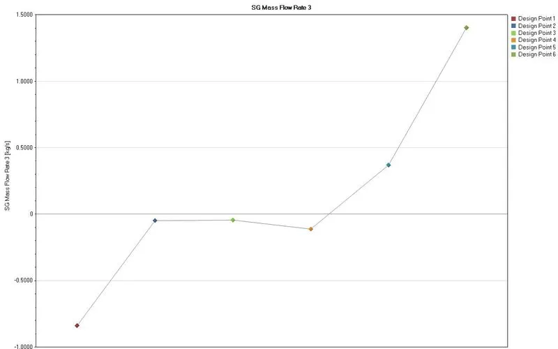
Parametric Study results -
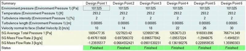
Outlet Pressure
Inlet mass flow
Outlet mass flow
Graph between Pressure ratio and Outlet Mass Flow rate :
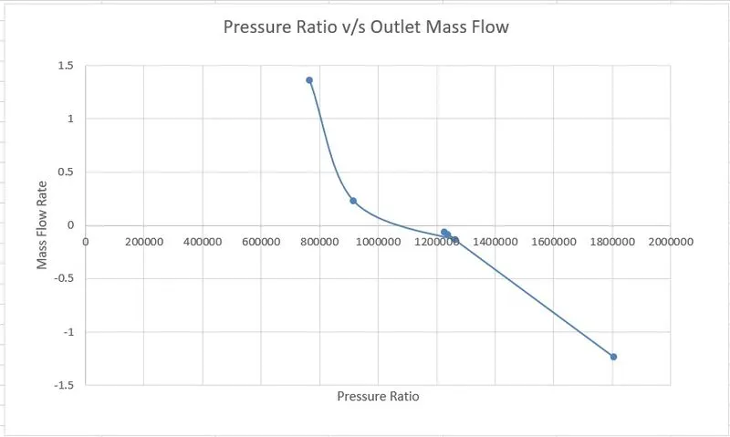
Conclusion : For comparison, positive values should be used.
Pressure ratio first increases then decreases with increase in velocity at outlet. This could be due to arbitrary dimensions or interaction between impeller and casing which can be improved with better designing of the whole 3D model.