Centrifugal pump design and analysis
Aim :
To perform design and simulation over a Centrifugal Pump and to plot the graph between pressure ratio and mass flow rate
Theory:
Centrifugal pump is a hydraulic machine which converts mechanical energy into hydraulic energy by the use of centrifugal force acting on the fluid. These are the most popular and commonly used type of pumps for the transfer of fluids from low level to high level.A pump is a device that moves fluids (liquids or gases), or sometimes slurries, by mechanical action, typically converted from electrical energy into Hydraulic energy. Pumps can be classified into three major groups according to the method they use to move the fluid: direct lift, displacement, and gravity pumps.
Different Types of Pumps: Working and Their Applications
There are different types of pumps available in the market.Here i will assist you to know the main functionalities of each type of pump. The type of pump, as well as selection, mainly depends on our requirements. The application mainly includes the type of fluid you desire to pump, the distance you desire to move the fluid, and the quantity you require to get over a particular time frame.
However, it is complicated to recognize accurately what kind of pump you must select. The identifying of the pump can be done with the design as well as positions. To make simpler things while seeking to choose your exact pump, and the pumps can be classified into two types which function in extremely dissimilar ways & generally summarize most of the pump designs.
1). Centrifugal Pumps
These types of pumps are most commonly used worldwide. The working is very simple, described well and carefully tested. This pump is strong, efficient and fairly cheap to make. Whenever the pump is in action, then the fluid pressure will increase from the inlet of the pump to its outlet. The change of pressure will drive the liquid throughout the system.
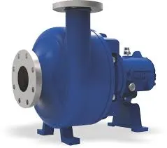
This kind of pump produces an enhancement within force by transmitting mechanical power from the electrical motor to the liquid throughout the revolving impeller. The flow of liquid will enter the center of impeller and exits along with its blades. The centrifugal power hereby enhances the velocity of fluid & also the energy like kinetic can be altered to force.
2). Vertical Centrifugal Pumps
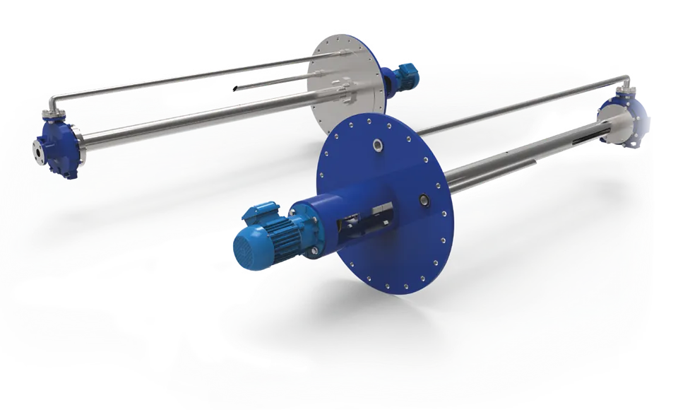
Vertical centrifugal pumps are also called as cantilever pumps. These pumps use an exclusive shaft & maintain design that permits the volume to fall within the pit as the bearings are external to the pit. This mode of pump utilizes no filling container to cover the shaft however in its place uses a throttle bushing. A parts washer is the common application of this kind of pump.
3). Horizontal Centrifugal Pumps
These types of pumps include a minimum of two otherwise more impellers. These pumps are utilized in pumping services. Every stage is fundamentally a divide pump.
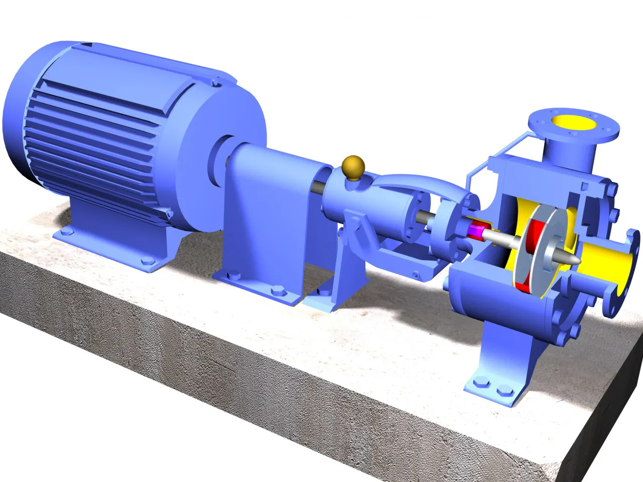
All the phases are in a similar shelter & mounted on a similar shaft. On a solo horizontal shaft, minimum eight otherwise additional stages can be mounted. Every stage enhances the head by around an equal amount. Multi-stage pumps can also be single otherwise double suction on the first impeller. All kinds of pumps have been providing as well as servicing this type of centrifugal pumps.
Thats enough information we need to know to understand my project.
Objective:
- Create 3D model of centrifugal pump of our own dimensions.
- Conduct a flow simulation by creating lids.
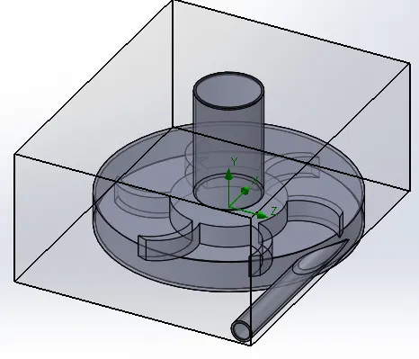
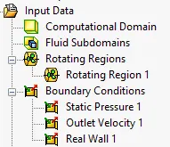
- Assign situable boundary conditions and goals to the design.
- Obtain the results and compare it to understand the outcomes.
Model:
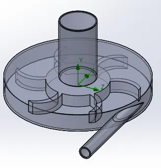
- Design a 3D model of centrifugal pump with our own dimensions.
- conduct the simulation with providing lids on both the openings to create a water tight system.
- Insert boundary conditions for inlet as pressure of 1 bar and outlet as Exit Velocity as a parametric study varing as,
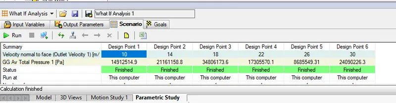
- Surface goals are set at inlet and outlet faces.
- Mesh is created for model at level 3 and advance channel refinement is selected to get a refined results
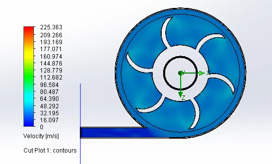
- Run the simulation for 300 iterations for cut plots of Velocity and pressure and flow trajectories .
Results :
Velocity plot:
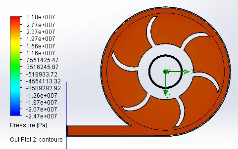
Pressure plot:
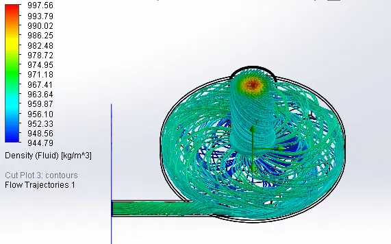
Flow trajectories :
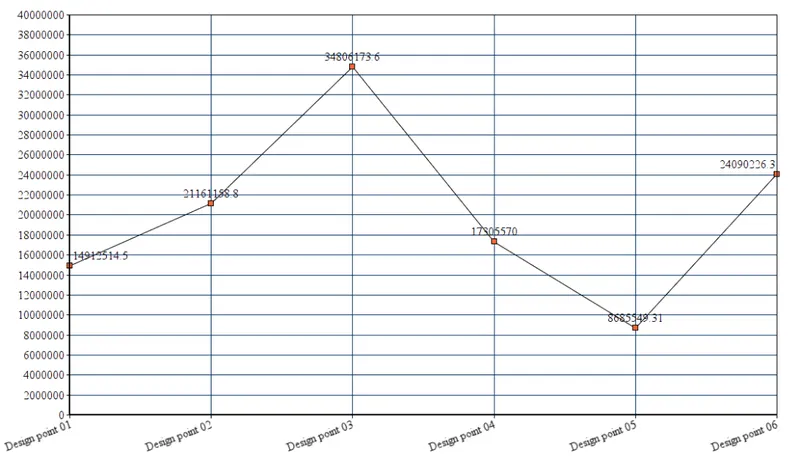
Variation of total pressure at inlet :

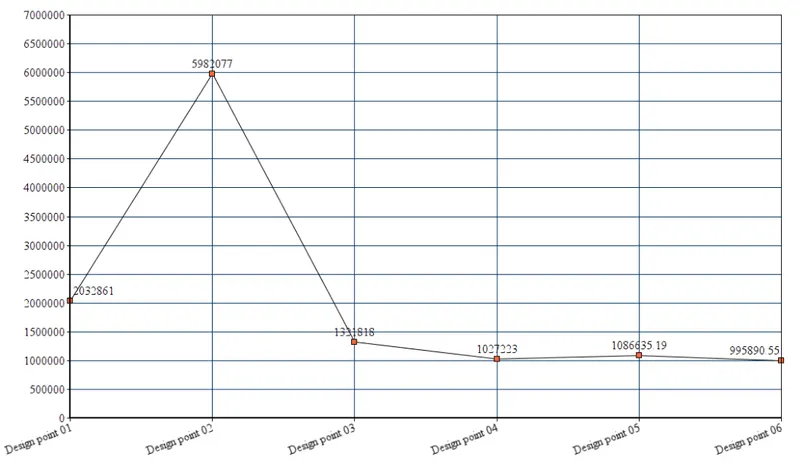
Surface goal total outlet pressure variation:
| SG Av Total Pressure Outlet [Pa] | 2032861 | 5982077 | 1321818 | 1027223 | 1086635.19 | 995890.55 |
| Design point | 01 | 02 | 03 | 04 | 05 | 06 |
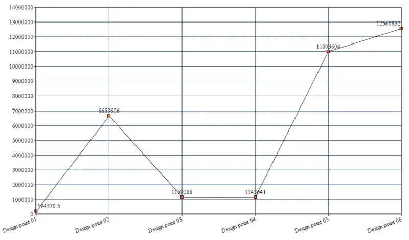
Surface goal total pressure variation:
| Design point | 01 | 02 | 03 | 04 | 05 | 06 |
| SG Av Total Pressure Inlet [Pa] | 194570.5 | 665362.6 | 115928.8 | 114364.1 | 110036.04 | 125608.32 |
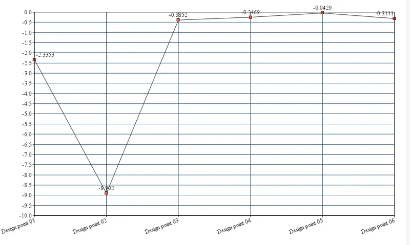
Surface goal Mass flow rate variation:
| Design point | 01 | 02 | 03 | 04 | 05 | 06 |
| SG Mass Flow Rate Inlet [kg/s] | -2.3353 | -8.902 | -0.3852 | -0.2469 | -0.0429 | -0.3111 |
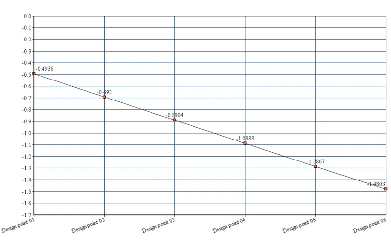
Surface goal Outlet Mass flow rate variation:
| Design point | 01 | 02 | 03 | 04 | 05 | 06 |
| SG Mass Flow Rate Outlet [kg/s] | -0.4936 | -0.692 | -0.8904 | -1.0888 | -1.2867 | -1.4803 |
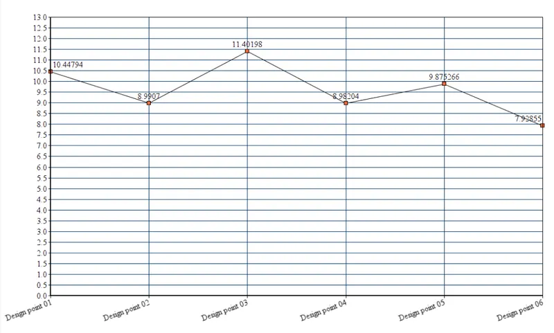
Pressure ratio variation :
| Design point | 01 | 02 | 03 | 04 | 05 | 06 |
| Pressure Ratio | 10.44794 | 8.9907 | 11.40198 | 8.98204 | 9.875266 | 7.92855 |
Conclusion :
- With increase in outlet velocity the mass flow rate showed a linear variation in the negative direction.
- The pressure ratio vs Velocity graph concludes that as the velocity increases the pressure ratio decreases.
- Hence Mass Flow Rate increases with a negative sign.
- When we comapre mass flow rate with the pressure ratio we can clearly see from the graph that it is inversly proportion, that is we can see that with the increase in mass flow rate the curve first rise and then it falls continously. We conclude that as an increase in mass flow rate, the pressure ratio value decreases upto certain limits after that pressure will become constant.
- We conclude that as an increase in mass flow rate, the pressure ratio value decreases upto certain limits after that pressure will become constant.