CENTRIFUGAL PUMP DESIGN AND ANALYSIS
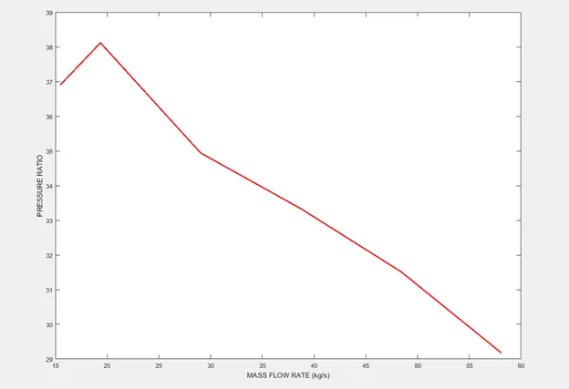
AIM: To design a centrifugal pump and analyze the flow simulation by plotting performance curve of mass flow rate and pressure ratio.
CENTRIFUGAL PUMP: It is a machine which is used to transport fluids by the conversion of rotational kinetic energy to the hydrodynamic energy of fluid flow. Common uses include water, sewage, agriculture, petroleum and petrochemical pumping.
WORKING PRINCIPLE: Inside a centrifugal pump, an impeller rotates on a drive shaft. The impeller accelerates the flow of the fluid handled. The centrifugal force moves the fluid towards the outer edge of the pump impeller. As a result, the fluid is transported to the outlet opening of the pump. At the same time, a negative pressure zone is created at the inlet opening, which draws the fluid further and further into the centrifugal pump. Even extremely large flow rates can be handled efficiently and continuously in powerful, continuous operation based on the principle.
COMPONENTS:
- CASING (SPIRAL or VOLUTE or SCROLL) : It is an air-tight passage of gradually diverging area which helps to convert kinetic energy into pressure energy or it decelerates the flow and further increases the pressure.
- IMPELLER: An impeller is a rotor used to increase the pressure and flow of fluid.
ROTATIONAL SPEED (also called speed, or speed of rotation): It is the number of revolutions a rotating system makes within a defined period of time. The pump speed is generally given in rpm. Most pumps operate at rotational speeds between 1000 and 3000 rpm but frequently reach in excess of 6000 rpm with special gearing and turbine drives.
The following relationship exists between rotational speed (n) and angular velocity (ω):-
ω = (π.n) /30
ω is angular velocity in rad/s
n is rotational speed speed in rpm
PROCEDURE:-
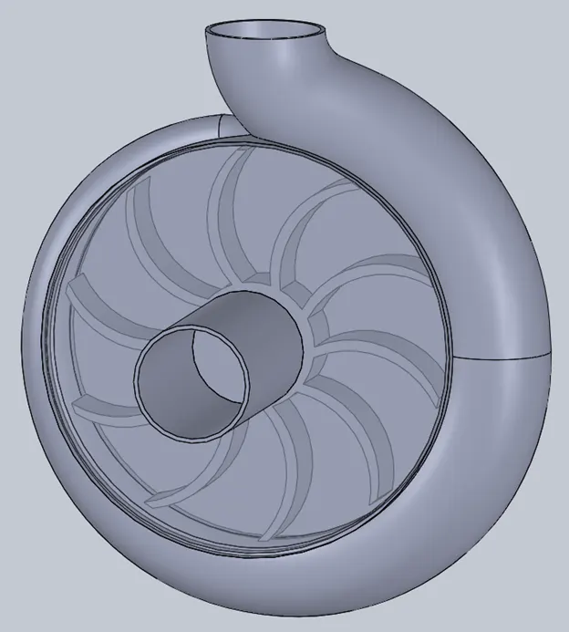
- Construct a volute casing for an impeller of required dimensions using loft and loft cut command by sketching different cross-sections.
- Draw a casing for an impeller of diameter 200.96 mm, thickness 3.68 mm and extrude it to a 60 mm depth. Close the casing from both ends by sketching a circle of 200.96 mm and extrude it to 2 mm. Use mirror command to close the other end of casing.
- Construct an impeller of diameter 190 mm. Extrude it to 25 mm.
- Construct an inlet pipe of 52 mm diameter and 2mm thickness.
- Using cut extrude cut the casing with dimensions equal to internal pipe diameter.
- Draw a circle of diameter 192.8 mm, greater than impeller diameter of 190 mm and extrude it to 28 mm. This is called rotating region for flow simulation.
- Uncheck merge option in extrude command so that all the parts are separated and not merged with one another.
- Go to flow simulation, create lids on inlet and outlet pipe of centrifugal pump and setup wizard.
- Take default fluid as water.
- In rotation option select local moving average.
- Go to component control option and uncheck the feature for rotating region.
- In rotating region enter angular velocity of -800 rad/s (7639.437 rpm) for rotation of impeller in anti-clockwise direction.
- Set global mesh level to 3 and check advanced channel refinement.
- Set boundary conditions by selecting inlet lid for environmental pressure and outlet lid for outlet velocity of 8 m/s.
- In surface goals select inside face of lid for average total pressure at inlet and outlet lid for average total pressure at outlet.
- In surface goals select inside face of outlet lid for mass flow rate.
- Go to calculation control option to enter value of iterations equal to 500.Uncheck all the finish conditions. This runs the simulation beyond goal convergence to find out if the goals are still changing or not. This value for number of iterations can be taken by running baseline simulations and observing the plots of goals, whether the goal plots are becoming constant or not after a number of iterations.
- Run the simulation.
- After the solver is finished make cut plots for velocity and pressure by selecting top plane. Hide the geometry to see the cut plots.
- Go to flow trajectories to insert velocity and pressure flow trajectories. Select inlet face of inlet pipe lid, then select outlet pipe lid.
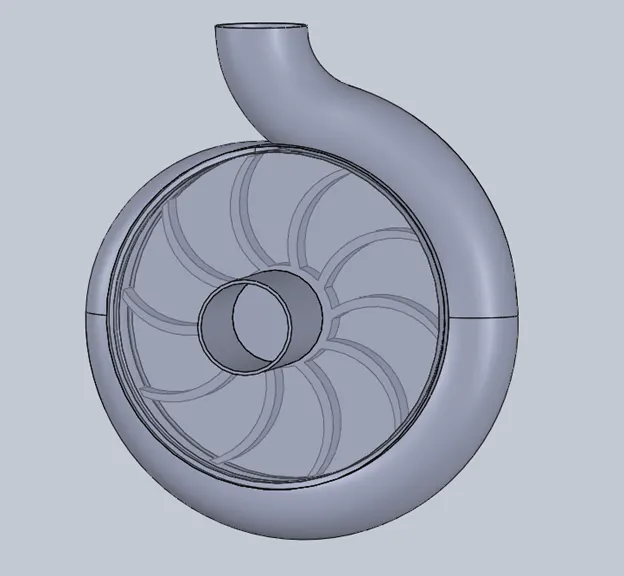
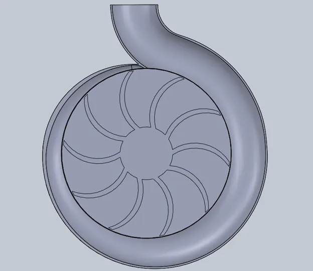
TOP SECTION VIEW
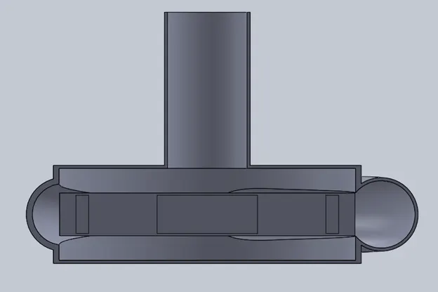
FRONT SECTION VIEW
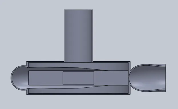
RIGHT SECTION VIEW
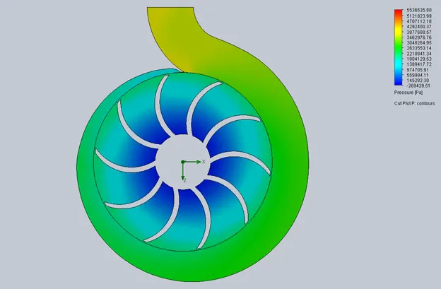
PRESSURE CUT PLOT (OUTLET VELOCITY 8 m/s)
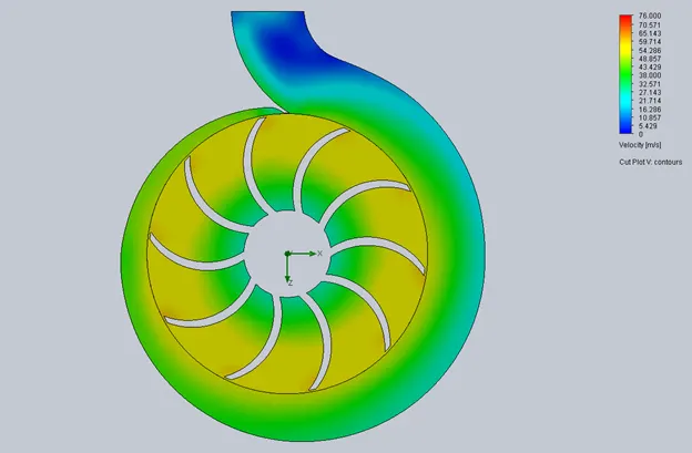
VELOCITY CUT PLOT (OUTLET VELOCITY 8 m/s)
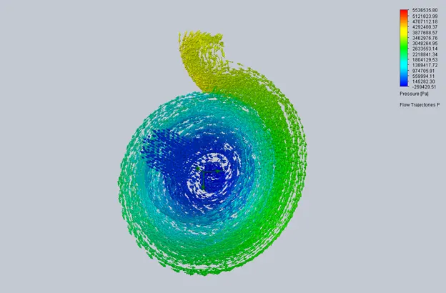
PRESSURE FLOW TRAJECTORIES (OUTLET VELOCITY 8 m/s)
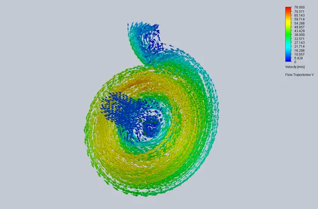
VELOCITY FLOW TRAJECTORIES (OUTLET VELOCITY 8 m/s)


PARAMETRIC STUDY
To run a parametric study select velocity normal to face boundary condition for input parameters. Click on variation type and select range with number to enter minimum, maximum, number of values for velocity at outlet. For output parameters select total pressure at inlet, total pressure at outlet, mass flow rate as goals. For results add cut plots and flow trajectories.
CUT PLOTS AND FLOW TRAJECTORIES:-
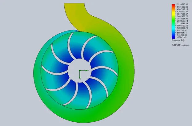
PRESSURE CUT PLOT (OUTLET VELOCITY 10 m/s)
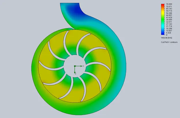
VELOCITY CUT PLOT (OUTLET VELOCITY 10 m/s)
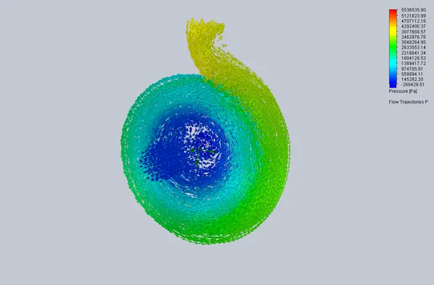
PRESSURE FLOW TRAJECTORIES (OUTLET VELOCITY 10 m/s)
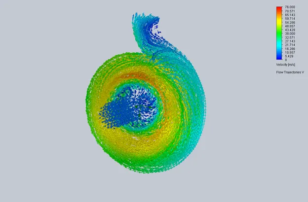
VELOCITY FLOW TRAJECTORIES (OUTLET VELOCITY 10 m/s)
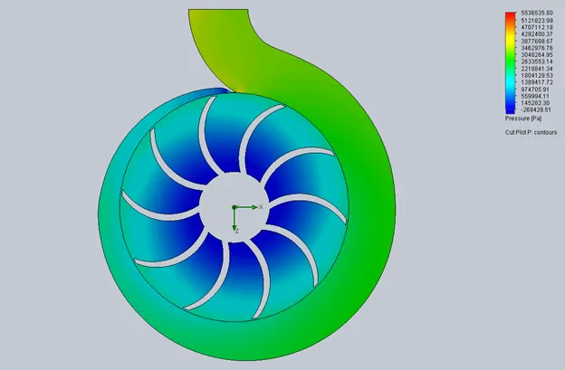
PRESSURE CUT PLOT (OUTLET VELOCITY 15 m/s)
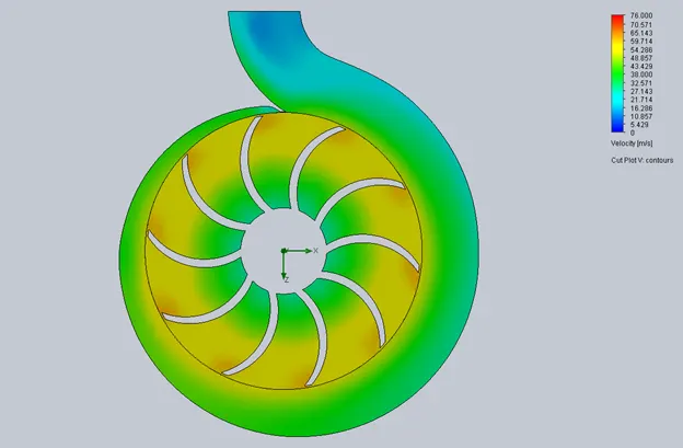
VELOCITY CUT PLOT (OUTLET VELOCITY 15 m/s)
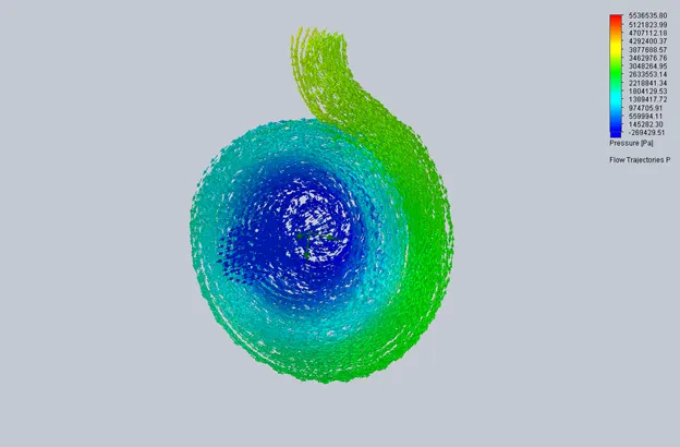
PRESSURE FLOW TRAJECTORIES (OUTLET VELOCITY 15 m/s)
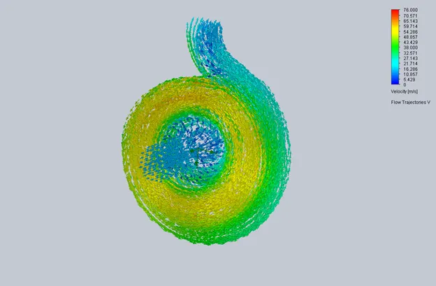
VELOCITY FLOW TRAJECTORIES (OUTLET VELOCITY 15 m/s)
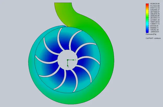
PRESSURE CUT PLOT (OUTLET VELOCITY 20 m/s)
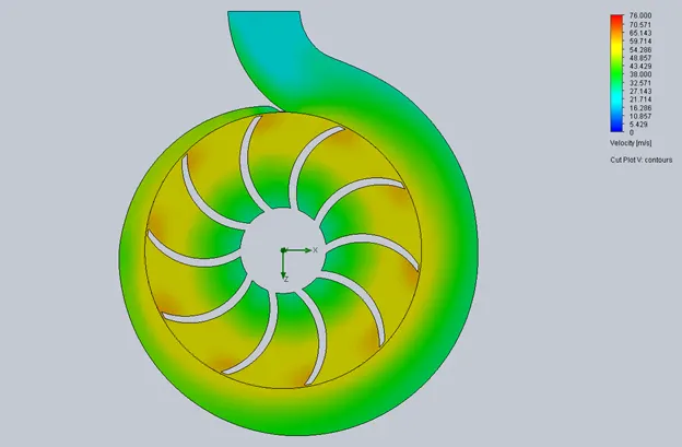
VELOCITY CUT PLOT (OUTLET VELOCITY 20 m/s)
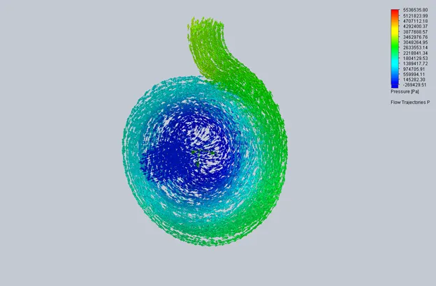
PRESSURE FLOW TRAJECTORIES (OUTLET VELOCITY 20 m/s)
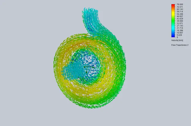
VELOCITY FLOW TRAJECTORIES (OUTLET VELOCITY 20 m/s)
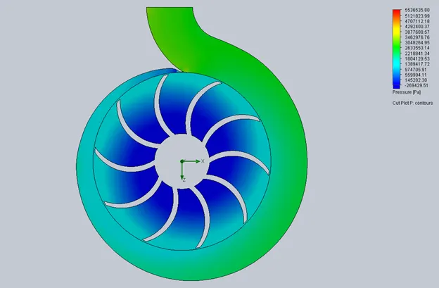
PRESSURE CUT PLOT (OUTLET VELOCITY 25 m/s)
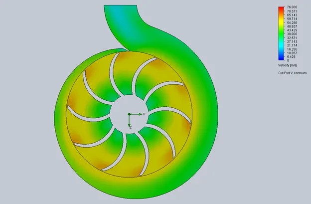
VELOCITY CUT PLOT (OUTLET VELOCITY 25 m/s)
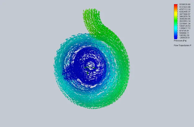
PRESSURE FLOW TRAJECTORIES (OUTLET VELOCITY 25 m/s)
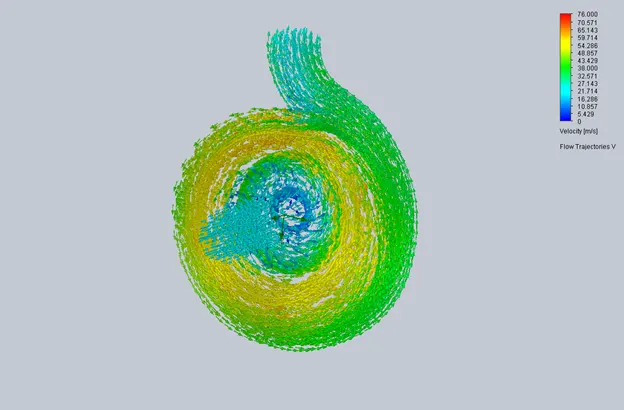
VELOCITY FLOW TRAJECTORIES (OUTLET VELOCITY 25 m/s)
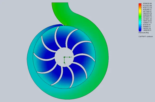
PRESSURE CUT PLOT (OUTLET VELOCITY 30 m/s)
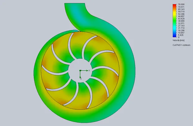
VELOCITY CUT PLOT (OUTLET VELOCITY 30 m/s)
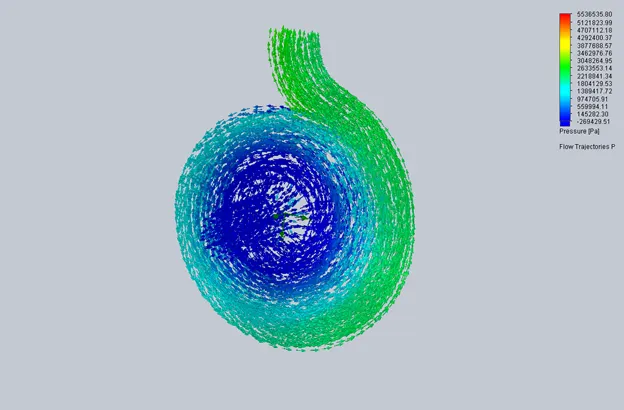
PRESSURE FLOW TRAJECTORIES (OUTLET VELOCITY 30 m/s)

VELOCITY FLOW TRAJECTORIES (OUTLET VELOCITY 30 m/s)


OBSERVATIONS: The above pressure and velocity cut plots show that pressure of fluid is increasing and velocity is decreasing as the area of cross-section of volute casing is increasing to the outlet of centrifugal pump. There is also a backflow of fluid at the outlet of pipe. But as the outlet velocity increases the flow becomes smoother at the outlet of pump.
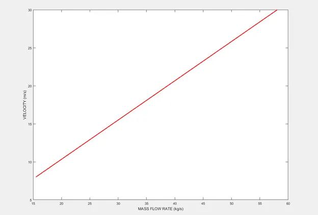
CONCLUSION: As the outlet velocity increases from 10 m/s to 30 m/s the pressure ratio decreases and mass flow rate increases.
|
OUTLET VELOCITY (m/s) |
PRESSURE RATIO (TOTAL PRESSURE 2/TOTAL PRESSURE 1) |
MASS FLOW RATE (kg/s) |
|
8 |
36.905 |
15.480 |
|
10 |
38.118 |
19.352 |
|
15 |
34.941 |
29.036 |
|
20 |
33.335 |
38.718 |
|
25 |
31.517 |
48.399 |
|
30 |
29.179 |
58.079 |
DESIGN IMPROVEMENT: To make wall thickness of volute uniform few changes were done in the part.
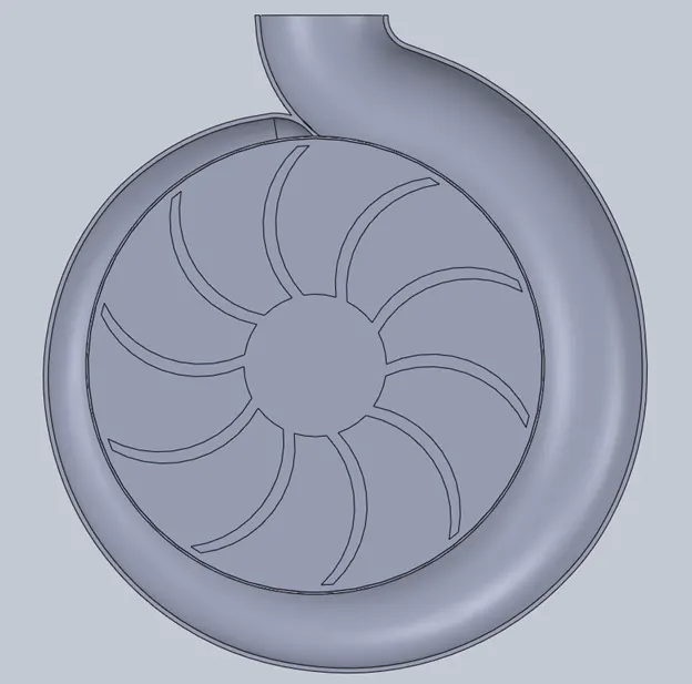
TOP SECTION VIEW
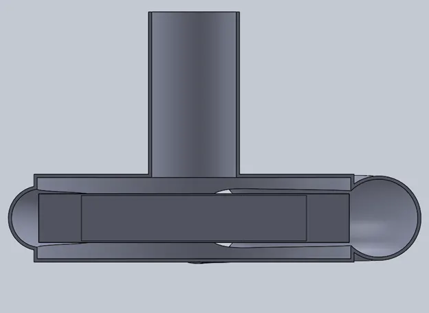
FRONT SECTION VIEW
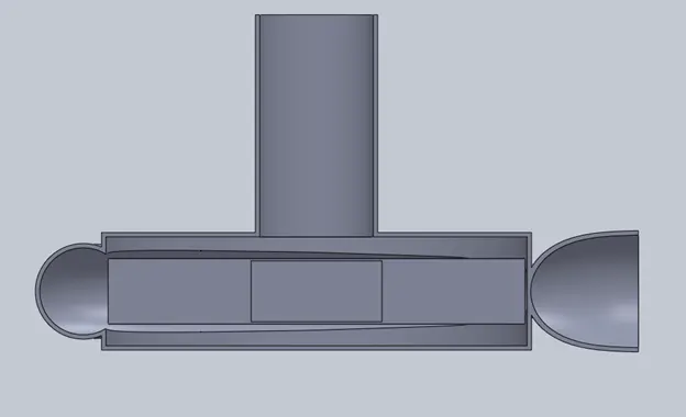
RIGHT SECTION VIEW
REFERENCES:-
1) WIKIPEDIA
2) KSB