Braking In EV's & HEV's || Regenerative Braking Stratregy || MS- Excel
BRAKING:
The term Braking comes from the term Brake. We know that brake is an equipment to reduce the speed of any moving or rotating equipment, like Vehicles, Locomotives. The process of applying brakes can be termed as Braking.
We can classify the term braking in two parts :-
- Mechanical Braking
- Electrical Braking
- Mechanical Braking:
Mechanical brakes are assemblies consisting of mechanical elements for the slowing or stopping of shafts in equipment drives. They use levers or linkages to transmit force from one point to another. Braking slows or stops the movement of the coupled shafts. A Mechanical Braking can also have several types according to there working principles, they could be:
- Disc Brake
- Drum Brake
- Engine Brake
- Exhaust Brake
In Mechanical Braking, the speed of the Machine is reduced solely by Mechanical process. But in Electrical braking, It is far more interesting than that because the whole process is depended on the Flux and Torque directions.
2. Electrical Braking:
Brakes are used to reduce or cease the speed of motors. We know that there are various types of motors available and the specialty and properties of these motors are different from each other, hence this braking methods also differs from each other. But we can divide braking in to three parts mainly, which are applicable for almost every type of motors.
- Regenerative Braking.
- Plugging type Braking.
- Dynamic Braking.
One of the most important features of electric vehicles (EVs) and hybrid electric vehicles (HEVs) is their ability to recover significant amounts of braking energy. The electric motors in EVs and HEVs can be controlled to operate as generators to convert the kinetic or potential energy of the vehicle mass into electric energy that can be stored in the energy storage and reused. The braking performance of a vehicle is undoubtedly one of the important factors to affect vehicle safety. A successfully designed braking system for a vehicle must always meet two distinct demands. Firstly, in emergency braking, it must bring the vehicle to rest in the shortest possible distance. Secondly, it must maintain control over the vehicle’s direction. The former requires that the braking system be able to supply sufficient braking torque on all the wheels. The latter requires braking force to be distributed on all the wheels equally. Generally, the braking torque required is much larger than the torque that an electric motor can produce. In EVs and HEVs, mechanically frictional braking systems must coexist with electrically regenerative braking. Thus, the proper design and control of both mechanical and electrical braking systems are major concerns.
We will be going through, Regenerative type of Electrical Braking Strategy.
Braking Power and Energy on Front and Rear Wheels :
Braking power and braking energy consumed by the front and rear wheels are closely related to the braking forces on the front and rear wheels. Afull understanding of the braking force, braking power, and braking energy consumed by the front and rear wheels in typical drive cycles is helpful in the design of regenerative braking systems. ignoring vehicle drags, the braking forces on the front and rear wheels can be expressed as:
`F_(bf)= (j.M_v/L).(L_b+h_g.j/G)`
and
`F_(br)= (j.M_v/L).(L_a-h_g.j/G)`
where j is the deceleration of the vehicle in m/s2,
L is the wheel base of the vehicle,
La and Lb are the horizontal distances between the vehicle gravity center to the center of the front and rear wheels, respectively,
and hg is the height of the gravity center of the vehicle to the ground
An Excel Sheet link is been attached,
Using, FTP- US06 Drive Cycle. We have calculated Force, Power and Energy required while Braking. We have also calculated the Front and the Rear Wheel braking force seperately. And there power and Energy Respectively. To be more precise, the Rear braking force should be lesser than, the Front Braking Force. And we can see that too.
https://drive.google.com/open?id=1w31OWjo8JEh03iPjzvkn-iRMzX0Q7gli
Brake System of EVs and HEVs:
- REGENERATIVE BRAKING:
Regenerative braking in EVs and HEVs adds some complexity to the braking system design.
Two basic questions arises:
- How to distribute the total braking forces required between the regenerative brake and the mechanical friction brake so as to recover the kinetic energy of the vehicle as much as possible.
- How to distribute the total braking forces on the front and rear axles so as to achieve a steady-state braking.
Usually, regenerative braking is effective only for the driven axle. The traction motor must be controlled to produce
the proper amount of braking force for recovering the kinetic energy as much as possible and, at the same time, the mechanical brake must be controlled to meet the braking force command from the driver.
Basically, there are three different brake control strategies:
- Series Braking With Optimal Braking Feel.
- Series Braking With Optimal Energy Recovery.
- Parallel Braking.
1. Series Braking With Optimal Braking Feel:
When the commanded deceleration (represented by the braking pedal position) is less than 0.2 g, only the regenerative braking on the front wheels is applied, which emulates the engine retarding function in conventional vehicles. When the commanded deceleration is greater than 0.2 g, the braking forces on the front and rear wheels follow the ideal braking forces distribution curve I, as shown in Figure.1 by the thick solid line. The braking force on the front wheels (driven axle) is divided into two parts: regenerative braking force and mechanically frictional braking force.
When the braking force demanded is less than the maximum braking force that the electric motor can produce, only electrically regenerative braking will apply. When the commanded braking force is greater than the available regenerative braking force, the electric motor will operate to produce its maximum braking torque, and the remaining braking force is met by the mechanical brake system.
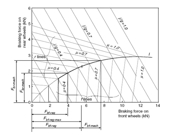
Fig.1 Illustration of braking forces on the front and rear axle for series braking — optimal feel
2. Series Braking With Optimal Energy Recovery:
The principle of the series braking system with optimal energy recovery is to recover the braking energy as much as possible in the condition of meeting the total braking force demanded for the given deceleration. This principle is illustrated in Fig.2.
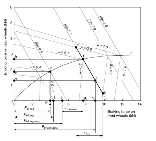
Fig.2 Demonstration of series braking — optimal energy recovery
When the vehicle is braked with an acceleration rate of j/g<μ, the braking forces on the front and rear wheels can be varied in a certain range, as long as the Fbf+Fbr=Mvj is satisfied. This variation range of the front and rear axles is shown in Figure 2 by the thick solid line ab, where μ=0.9 and j/g= 0.7. In this case, regenerative braking should be used in priority. If the available regenerative braking force (maximum braking force produced by the electric motor) is in this range (point c in Figure 2, for example), the braking force on the front wheels should be developed only by regenerative braking without mechanical braking. The braking force on the rear wheels, represented by point e, should be developed in order to meet the total braking force requirement. If, on the same road, the available regenerative braking force is less than the value corresponding to point a (e.g., point i in Figure 2), the electric motor should be controlled to produce its maximum regenerative braking force. The front and rear braking forces should be controlled at point f so as to optimize the driver feel and reduce braking distance. In this case, additional braking force on the front wheels must be developed by mechanical braking by the amount represented by Fbf-mech, and the braking force on the rear axle is represented by point h.
When the commanded deceleration rate, j/g, is much smaller than the road adhesive coefficient (j/g=0.3 in Figure 2 for example), and the regenerative braking force can meet the total braking force demand, only regenerative braking is used without mechanical braking on the front and rear wheels (point j in Figure 2).
When the commanded deceleration rate, j/g, is equal to the road adhesive coefficient µ , the operating point of the front and rear braking forces must be on the curve I. On a road with a high adhesive coefficient ( µ =0.7, operating point f, in Figure 2, for example), the maximum regenerative braking force is applied and the remaining is supplied by the mechanical brake. On a road with a low adhesive coefficient ( µ =0.4, operating point k, in Figure 2, for example), regenerative braking alone is used to develop the front braking force. When the commanded deceleration rate, j/g, is greater than the road adhesive coefficient µ , this commanded deceleration rate will never be reached due to the limitation of the road adhesion. The maximum deceleration that the vehicle can obtain is (a/g)max= µ . The operating point of the front and rear braking forces is on the curve I, corresponding to µ ( µ =0.4 and j/g=0.4 in Figure 2, for example); the operating point is point k and the maximum deceleration rate is j/g=0.4. It should be noted that the series brake with both optimal feel and energy recovery needed active control of both electric regenerative braking and mechanical braking forces on the front and rear wheels. At present, such a braking system is under research and development.
3.parallel braking:
The parallel brake system includes both an electrical (regenerative) brake and a mechanical brake, which produce braking forces is parallel and simultaneously. The operating principle is illustrated in Figure 3, in which regenerative braking is applied only to the front wheels.
The parallel brake system has a conventional mechanical brake which has a fixed ratio of braking force distribution on the front and rear wheels. Regenerative braking adds additional braking force to the front wheels, resulting in the total braking force distribution curve. The mechanical braking forces on the front and rear axles are proportional to the hydraulic pressure in the master cylinder. The regenerative braking force developed by the electric motor is a function of the hydraulic pressure of the master cylinder, and therefore a function of vehicle deceleration. Because the regenerative braking force available is a function of motor speed and because almost no kinetic energy can be recovered at low motor speed, the regenerative braking force at high vehicle deceleration (e.g., a/g_0.9) is designed to be zero so as to maintain braking balance. When the demanded deceleration is less than this deceleration, regenerative braking is effective. When the braking deceleration commanded is less than a given value, say 0.15 g, only regenerative braking is applied. This emulates the engine retarding in a conventional vehicle. In Figure 3, the regenerative braking force, Fbf-regen, and mechanical braking forces on the front and rear wheels, Fbf-mech and Fbr, are illustrated. Figure 4 shows the total braking force, regenerative braking force, and mechanical braking force on the front wheels as well as the braking force on the rear wheels in the parallel braking system of a passenger car.
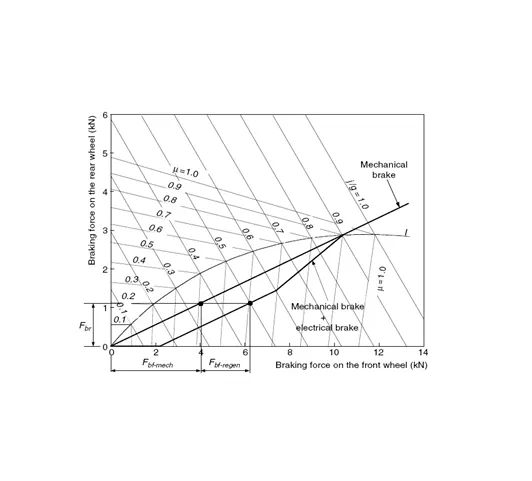
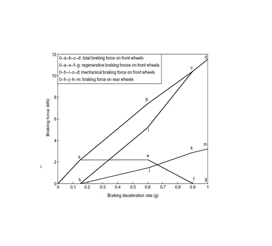
Fig. 3 Illustration of parallel braking strategy Fig.4 Braking forces varying with deceleration rate
The parallel braking system does not need an electronically controlled mechanical brake system. A pressure sensor senses the hydraulic pressure in the master cylinder, which represents the deceleration demand. The pressure signal is regulated and sent to the electric motor controller to control the electric motor to produce the demanded braking torque. Compared with the series braking of both optimal feel and energy recovery, the parallel braking system has a much simpler construction and control system. However, the driver’s feeling, and amount of energy recovered are compromised.