Braking & Efficiency Mapping of Electric Motors
BRAKING & Efficiency Mapping
AIM:
- To study on the Energy required during Braking based on any Drive Cycle.
- To study on Electric Braking & Mechanical Braking and Characteristics of Electric Motor Braking.
- To script a MATLAB program to evaluate plots for Speed, Torque & Efficiency Values.
-------------------------------------------------------------------------------------------------------------------------------------
- Braking Energy
A driving cycle is a series of data points representing the speed of a vehicle versus time. Driving cycles are produced by different countries and organizations to assess the performance of vehicles in various ways, as for instance fuel consumption, electric vehicle autonomy and polluting emissions. Fuel consumption and emission tests are performed on chassis dynamometers. Tailpipe emissions are collected and measured to indicate the performance of the vehicle.
Another use for driving cycles is in vehicle simulations. More specifically, they are used in propulsion system simulations to predict performance of internal combustion engines, transmissions, electric drive systems, batteries, fuel cell systems, and similar components.
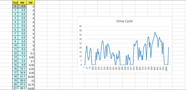
I am using a common Drive Cycle derived based on typical Indian Roads.
Braking is the process of controlling the velocity of an object by inhibiting its motion. An object in motion possesses kinetic energy and to bring the object to a stop this kinetic energy must be removed. Removing the kinetic energy can be accomplished by dissipating the energy to the atmosphere through friction or by converting it into another form of energy. The most common type of braking is a mechanical brake which inhibits motion through friction brake pads. A mechanical brake applies a friction force to convert the kinetic energy of the vehicle into thermal energy which then dissipates into the atmosphere.
As with any system, the process of braking must follow the principal of conservation of energy. Energy cannot be created or destroyed but only converted from one form to another,
ΣEin=ΣEout
The energy present in an object in motion is given by the following equation:
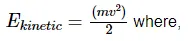
- m is the mass of the object in kilograms (kg).
- v is the velocity of the object in meters per second (m/s).
- Ekinetic is the kinetic energy in joules (J)
Velocity will be (V-Vi), Where V is absolute speed of vehicle & Vi is the speed to which vehicle is brought down or rest.
MATLAB Program to calculate Braking Energy
clear all
close all
clc

%Read the Drive Cycle data from given .xls file
DC=xlsread('common DC.xlsx');
T=DC(:,1);  %Time in Seconds
S=DC(:,4);  %Speed in Kmph

%other data
m=500; %mass in Kg
V=S./3.6; %Speed in m/s

%To create an Array to store values for Deceleration & Braking Energy
Z=length(T);
deceleration=zeros(1,Z);
acceleration=zeros(1,Z);
BE=zeros(1,Z);
AE=zeros(1,Z);

for i=1:(length(T)-1)
    if V(i)>V(i+1)
        BE(i)=0.5*m*(V(i)-V(i+1))^2; %Braking Energy in Joules

        speed_decrease(i)=V(i+1)-V(i);
        deceleration(i)=speed_decrease(i);
        %since Time Delta is 1s Acc/dec=V/T..m/s^2, where T=1
    end

    if  V(i)<V(i+1)
        AE(i)=0.5*m*(V(i)-V(i+1))^2; %Accelerating Energy in Joules

        speed_increase(i)=V(i+1)-V(i);
        acceleration(i)=speed_increase(i);
    end

end

%Total Braking Energy in KJ
B_E=(sum(BE)/1000);
%Total Accelerating Energy in KJ
A_E=(sum(AE)/1000);

%Plotting Curves
figure(1)

subplot(2,1,1)
plot(T,S,'color','b')
xlabel('Time(s)')
ylabel('Speed(Kmph)')
title('Drive Cycle')

subplot(2,1,2)
plot(T,deceleration,'color','r')
hold on
plot(T,acceleration,'color','g')
xlabel('Time(s)')
ylabel('Acc/Dec(m/s^2)')
title('Acceleration-Deceleration')

figure(2)
plot(T,BE)
hold on
plot(T,AE)
xlabel('Time(s)')
ylabel('Energy(J)')
title('Energy consumed during Braking & required for accelerating throughout Drive Cycle')
legend('Braking Energy','Accelerating Energy')

fprintf('Total Energy consumed during Braking is %f KJ',B_E)
disp(' ')
fprintf('Total Energy consumed during Acceleration is %f KJ',A_E)
Program Explanation
- Initially Excel file containing the values of Drive Cycle has been read using xlsread command and respective Time and Speed values are extracted into Array.
- Vehicle mass and Speed values into desired units are obtained.
- An empty/zero Array are created to append the values in the for loop.
- for loop for the length of time value has been created.
- Acceleration & Deceleration cases are solved inside the for loop based on the speed values.
- Total Energy consumed is calculated.
- Desired curves are plotted.
Result
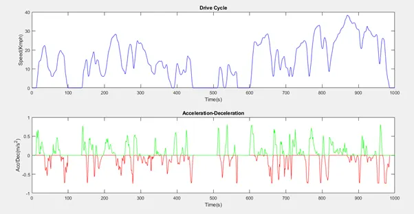
From the above plot
- Drive Cycle can be visualized.
- Acceleration Deceleration Curves based on given Drive Cycle can be seen.
- Green Curve shows Acceleration region & Red Curve shows Braking region.
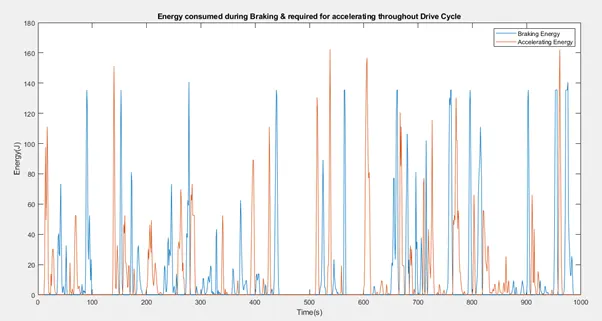
- Braking Energy consumed and Energy required during Acceleration can be seen from the above plot.

--------------------------------------------------------------------------------------------------------------------------------
- Why Electric Motor can’t develop Braking Torque @ High Speed similar to Starting Torque? How are Electric & Mechanical Brakes are coordinated?
Considering the example of an Induction Motor to clearly understand,
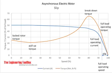
Starting Torque (Locked Rotor) is the torque an electrical motor develops when starting at zero speed. A high Starting Torque is more important for application or machines hard to start - like positive displacement pumps, cranes etc. A lower Starting Torque can be accepted for centrifugal fans or pumps where the start load is low or close to zero.
For rotating machines (like electric motors in vehicles) since the moment of inertia is high, and the torque is rotational moment, starting torque will be higher.
Since the case is different in Braking, where the motor is already at some speed and tends to be in motion and braking opposes the induced torque and hence does not develop further more torque adversely.
Coordination of Electric & Mechanical Braking
Mechanical Braking is typical or conventional kind of braking which are most common in Automobiles, which acts by generating frictional forces between 2 surfaces.
Mechanical brakes are assemblies consisting of mechanical elements for the slowing or stopping of shafts in equipment drives. They use levers or linkages to transmit force from one point to another. Braking slows or stops the movement of the coupled shafts. There are several types of mechanical brakes. Band brakes, the simplest brake configuration, have a metal band lined with heat and wear resistant friction material. Drum brakes, which are commonly used on automobile rear wheels, work when shoes press against a spinning surface called a drum. Disc brakes are constructed of brake pads, a calliper, and a rotor. During operation, the brake pads are squeezed against the rotor. Cone brakes are made with a cup and a cone, which is lined with heat and wear resistant material. During actuation, the cone is pressed against the mating cup surface.
The Disc Brake is a device for slowing or stopping the rotation of a wheel while it is in motion. A brake disc is usually made of cast iron, but may in some cases be made of composites such as reinforced carbon-carbon or ceramic -matrix composites. This is connected to the wheel and/or the axle. To stop the wheel, friction material in the form of brake pads (mounted on a device called a brake calliper) is forced hydraulically, pneumatically or electromagnetically against both sides of the disc. Friction causes the disc and attached wheel to slow or stop. Brakes convert motion to heat, and if the brakes get too hot, they become less effective, a phenomenon known as brake fade.
Drum Brake is a brake in which the friction is caused by a set of shoes or pads that press against a rotating drum-shaped part called a brake drum. The term "drum brake" usually means a brake in which shoes press on the inner surface of the drum. When shoes press on the outside of the drum, it is usually called a clasp brake. Where the drum is pinched between two shoes, similar to a conventional disk brake, it is sometimes called a "pinch drum brake", although such brakes are relatively rare. A related type of brake uses a flexible belt or "band" wrapping around the outside of a drum, called a band brake.
Electrical Braking
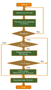
Regenerative braking takes place whenever the speed of the motor exceeds the synchronous speed. This baking method is called regenerative braking because here the motor works as generator and supply itself is given power from the load, i.e. motors. The main criteria for regenerative braking are that the rotor has to rotate at a speed higher than synchronous speed, only then the motor will act as a generator and the direction of current flow through the circuit and direction of the torque reverses and braking takes place.
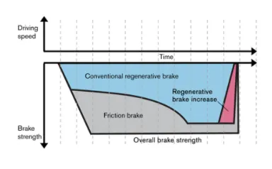
Regenerative braking is a system that utilizes the mechanical energy from the motor by converting kinetic energy into electrical energy and fed back to the sources of energy. The combined action of mechanical and electric brake is proposed as a means of minimizing the inefficiency and poor controllability of RB at low speeds, ensuring the expected behaviour for the slowdown.
In an electric vehicle, when the speed is reduced, the electric machine can operate as a generator. Such process depends on the topology and on the control applied to power electronic converter that drives the electric machine.
--------------------------------------------------------------------------------------------------------------------------------
- To script a MATLAB program to evaluate plots for Speed, Torque & Efficiency Values.
%Efficiency Mapping for Electric Motors
clear all
close all
clc
x=linspace(1,1000); % speed in rad/s
y=linspace(1,250); % Torque in Nm

% Motor loss constants
Kc=0.2;  %Copper Loss
Ki=0.008; %Iron Loss
Kw=0.00001; % Winding Loss
C=20; % constant motor losses

[X,Y]=meshgrid(x,y);
Output_Power=(X.*Y);

C_l=(Y.^2)*Kc; %Copper Loss
I_l=(X*Ki); %Iron Loss
W_l=(X.^3)*Kw; %Winding Loss

Input_Power=Output_Power+C_l+I_l+W_l+C;

Z=Output_Power./Input_Power;

V=[0.70,0.80,0.85,0.90,0.91,0.92,0.925,0.93];

box off
grid off

[c,h]=contour(X,Y,Z,V);
xlabel('Speed(rad/s)');
ylabel('Torque(N/m)');
clabel(c,h);
Program Explanation
- Initially array for storing the values for Speed and Torque are created using linspace command.
- A 2D grid of the above arrays are created using meshgrid command.
- Various Motor loss constants/Coefficients are defined and stored.
- Now the Motor losses are calculated
- Copper Losses Kc.T^2
- Iron Losses Ki.W
- Windage Losses Kw.W^3
- Input Power and Output Power are calculated.
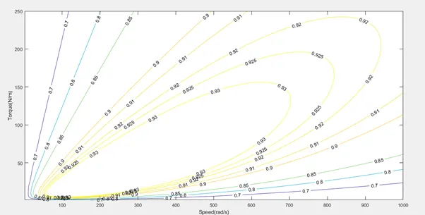
- Finally, the Efficiency of motor using above values.
- A contour od the Torque Speed curves are plotted and efficiency is mapped using clabel command.
Result
**************************************************************************************************************************************************************************************