Boeing-747 _ Final_Project
MODELLING AND ASSEMBLY OF BOEING 747-8 USING SOLIDWORKS
OBJECTIVE:
- To set up the blueprints for Boeing 747-8.
- To model the individual parts of the Boeing 747-8 using SolidWorks.
- To assemble all the parts with proper mates.
- To give proper appearances and decals for the parts.
- To position the assembly and set up cameras, lights and environments.
- To create photorealistic renders using SolidWorks Visualize.
INTRODUCTION:
SolidWorks is a 3D CAD and CAE software developed by Dassault Systèmes. It provides dedicated tools and workflows that streamline the design and development of products. It is used for sketching, part modelling, sheet metal design, simulation, mold design, and other computer-aided manufacturing processes.
SolidWorks Visualize is a software used to create photorealistic or non-photorealistic renders. It is also used for post-processing images and even creating basic presentation animations.
Boeing 747-8 is the largest variant of the Boeing 747 range of wide-body jet airliners developed by Boeing Commerical Airplanes. This variant has been initially launched on November 14, 2005 and it began commercial service in June 2012. It was designed to compete against the Airbus's Airbus A3XX.
DESIGN METHODOLOGY:
Here the Boeing 747-8 is assembled by following Bottom-up Approach. In this approach all the parts are modelled in individual part files and assembled together in a common assembly file. This method is generally used for off-the-shelf components which can be readily assembled in an assembly line. This approach makes it easy to configure individual components for different specifications.
The process can be explained with the help of the following flowchart:

Fig. Flowchart of the Design Approach for Boeing 747-8
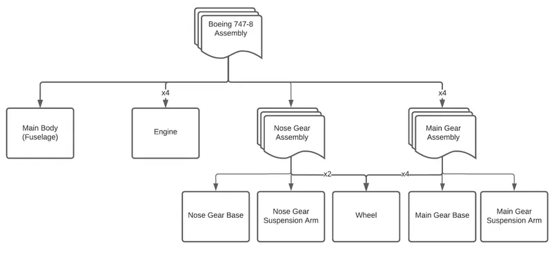
Fig. Flowchart of the Modelling and Assembly Process for Boeing 747-8
DESCRIPTION:
Setting up the Blueprint:
Prior to modelling individual components, a Blueprints file is created using the design sketches. This can be used as a reference for modelling most of the components.
Sketch tools and Features used in Blueprint setup:
- Sketch
- Sketch Picture
Sketch: It is a two-dimensional representation of the body in a plane. It needs to be completely defined with proper geometric relations and dimensions.
Sketch Picture: It inserts an image file on a selected plane to be used as a reference to model components.
Fig. Isometric View of Blueprint Setup for Boeing 747-8
The Boeing 747-8 assembly constitutes the following components and sub-assemblies:
- Main Body
- Fuselage
- Belly Fairing
- Nose Cone
- Pitot Tubes
- Cockpit Windows
- Windshield Wipers
- Passenger Windows
- Doors and Hatches
- Lights and Antennas
- Auxiliary Power Unit
- Vertical and Horizontal Stabilizers
- Wings
- Flaps and Ailerons
- Landing Gear Axes
- Landing Gear Hatches (Closed and Open)
- Livery
- Engine
- Nose Gear Assembly
- Nose Gear Base
- Nose Gear Suspension Arm
- Wheel
- Main Gear Assembly
- Main Gear Base
- Main Gear Suspension Arm
- Wheel
The parts are modelled individually in designated part files and saved in a dedicated folder for better organisation.
1. Main Body:
The Main Body of Boeing 747-8 carries majority of the components explained below:
- Fuselage: The Fuselage comprises the main body of the airplane and holds all the crew, passengers or cargo. It bears the wings, stabilizers, hatches and doors, passenger windows, among other features. The fuselage is lengthened from 232ft to 251ft making Boeing 747-8 to be the first stretch variant of the Boeing 747 aircraft. The basic structure is kept the same as the original but the wing is thicker and deeper to hold more fuel.
Sketch Tools and Features used in modelling Fuselage:- Sketch
- Line
- Spline
- Smart Dimension
- Convert Entities
- Fillet
- Projected Curve
- Lofted Surface
- Mirror
- Thicken
- Belly Fairing: Fairing is a structure in an aircraft to produce smooth outline and reduce drag. A Belly Fairing also known as "ventral fairing", is located on the underside of the fuselage between the main wings and can cover additional cargo storage or fuel tanks.
New Sketch Tools and Features used in modelling Belly Fairing:- Centerline
- Split
- Extruded Base/Boss
- Fillet
- Combine
- Nose Cone: is the conically shaped forwardmost section of an aircraft, designed to modulate oncoming airflow behaviours and minimize aerodynamic drag. It also works as a radar-dome protecting the weather radar from aerodynamic forces.
New Sketch Tools and Features used in modelling Nose Cone:- Offset Entities
- Split Line
- Circle
- Trim
- Swept Boss/Base
- Pitot Tubes: are flow measurement instruments to measure the airspeed of an aircraft.
New sketch Tools and Features used in modelling Pitot Tubes:
- Reference Geometry (Axis)
- Reference Geometry (Plane)
- Chamfer
- Extruded Cut
- Cockpit Windows: are the openings at the cockpit section, which allow the pilot(s) to navigate the aircraft. They are usually made of Perspex (PMMA) material and have an anti-reflective coating and an internal heating element to melt ice.
New sketch tools and Features used in modelling Cockpit Windows:- Centerpoint Arc
- Point
- Surface Offset
- Windshield Wipers: are devices to remove water, snow, ice and/or debris from the windshield. A wiper usually is a metal arm, which pivots about one end and fitted with a rubber blade on the other end.
New sketch tools and Features used in modelling Windshield Wipers:
- Shell
- 3D Sketch
- Move Body
- Slot
- Passenger Windows: are enclosed openings in the fuselage which allow the passengers and cabin crew to have a view outside the aircraft. They are equipped with pressure adjusting equipment to adjust the cabin pressure according to the pressure outside the aircraft and collapsible sun visors.
New sketch tools and Features used in modelling Passenger Windows:
- Create Block
- Insert Block
- Linear Sketch Pattern
- Doors and Hatches: are exits for the crew or passengers or cargo to enter or exit the aircraft. They are located strategically so that all the crew and passengers can exit the aircraft quickly in case of any emergency.
New sketch tools and Features used in modelling Doors and Hatches:
- Linear Pattern
- Lights and Antennas: are located on the body of the aircraft and its wings for air traffic communication as well as identification.
New sketch tools and Features used in modelling Lights and Antennas:- Revolved Boss/Base
- Draft
- Dome
- Auxiliary Power Unit: consists of the exhaust and tail lights at the rear end of the aircraft body.
- Vertical and Horizontal Stabilizers: are features to provide stability to the aircraft during flight in both vertical and horizontal planes.
New sketch tools and Features used in modelling Vertical and Horizontal Stabilizers:
- Lofted Boss/Base
- Variable Fillet
- Wings: are fin-like structures to produce lift as the aircraft moves through air. They have streamlined cross-sections that are subject to aerodynamic forces and act as aerofoils. They also act as fuel tanks in large airliners to reduce the volume and weight needed in providing a dedicated fuel tank. They hold other features such as the engines, flaps, ailerons and flap track fairings for the optimum working of the aircraft.
New sketch tools and Features used in modelling Wings:
- Cut with Surface
- Delete Body
- Flaps and Ailerons: are devices to control the motion of the aircraft along different axis. Flaps are retractable high-lift devices used to reduce the stalling speed of an aircraft wing at a given weight. They are used to control the pitch motion of an aircraft. Ailerons are hinged flight control surfaces usually forming part of the trailing edge of each wing of a fixed-wing aircraft. They are used in pairs to control the roll of an aircraft.
- Flap Track Fairings: are used to enclose the flap operating mechanism when the flap is lifted up.
- Landing Gear Axes: are reference to locate the landing gears.
- Landing Gear Hatches (Closed and Open): are openings which allow the landing gears to retract after take-off and expand before landing.
New sketch tools and Features used in modelling Landing Gear Hatches (Closed and Open):
- Center-Rectangle
- Parallelogram
- Swept Surface
- Livery: is an identifying design such as a symbol or insignia that designates the ownership or affiliation. Here,
New sketch tools and Features used in modelling Livery:- Text
- Circular Sketch Pattern
- Add Appearance
- Edit Appearance
The features used in modelling the Main body are explained below:
- Line: This tool is used to create a straight line with a defined position and length.
- Spline: It is used to create a curve with defined endpoints. The curvature can be altered by enabling the curve handlers which can be given a defined direction and strength.
- Smart Dimension: It is used to provide proper dimensions to a sketch feature and automatically provides the relevant dimension for a particular selection.
- Convert Entities: This tool is used to convert entities from other features into the sketch.
- Fillet: It creates a circular feature to the selected edges or faces in a sketch. This is often used to round off sharp edges in a sketch.
- Lofted Surface: It creates a surface which transitions between two or more profiles or sketches.
- Mirror: It creates an exact copy of a feature about a selected plane or face.
- Thicken: It creates a solid body by adding thickness to one or more adjacent surfaces.
- Centerline: This tool is used to create a straight line for construction with a defined position and length.
- Offset Entities: It is used to copy the sketch entities with the same shape and proportional dimension at a distance.
- Split: It is used to create multiple bodies form a single body with the help of a split tool such as a sketch or a plane.
- Extruded Boss/Base: It creates a solid body by giving thickness to the selected sketch contours.
- Fillet: It is used to smoothen the sharp edges of a solid body by giving a radius value as an input.
- Projected Curve: It creates a 3D curve that represents the intersection of the two extruded surfaces generated by creating sketches on two intersecting planes.
- Combine: It is used to combine two or more solid bodies.
- Split Line: It projects entities on to surfaces or curved faces and divides the targeted features.
- Circle: This tool is used to create a circle with a defined center and a diameter.
- Trim Entities: This tool is used to remove sketch entities with respect to certain references.
- Swept Boss/Base: It creates a solid body by moving a specified sketch profile or a defined circular along a defined path.
- Reference Geometry: It creates reference entities such as a point or an axis or a plane or even a coordinate system.
- Chamfer: It is used to remove and flatten sharp edges on a solid body.
- Extruded Cut: It removes material from a solid body with the help of sketched contours.
- Centerpoint Arc: This tool is used to create an arc with its center and two endpoints specified.
- Point: It is used to create a point on the sketch.
- Offset Surface: It creates a surface at a specified distance for a selected planar face or surface.
- Shell: It creates a hollow feature from a solid body with a specified thickness.
- 3D Sketch: It is used to create sketches in three dimensions rather than a planar face or plane.
- Move Body: It is used to move a body specifying the from and to points or co-ordinates.
- Slot: It is used to create a slot with specified length and diameter.
- Create Block: It is used to create a new sketch block from the current sketch selection.
- Insert Block: It is used to insert a sketch block into the current sketch.
- Linear Sketch Pattern: It creates duplicates of a sketch entity in a specified linear direction for a specified number of instances.
- Linear Pattern: It creates duplicates of a feature or a body in a specified linear direction for a specified number of instances.
- Revolved Boss/Base: It creates a solid body by giving thickness to the selected sketch contours about an axis of revolution.
- Draft: It is used to provide a taper to the faces of a model by a specified angle using a neutral plane or a parting line.
- Dome: It is used to create a curvature about an end face.
- Lofted Boss/Base: It is used to create a solid body with the help of at least two sketches as the transition faces and at least one sketch as a guide curve.
- Variable Fillet: It is used to smoothen the sharp edges of a solid body by giving variable radius values as inputs at specified points along the edge.
- Cut with Surface: It is used to cut a solid by removing material with a surface or a plane.
- Delete Body: It is used to delete selected bodies from the file.
- Center-Rectangle: It is used to create a rectangle with its center defined first and then one of its vertices specified.
- Parallelogram: It is used to create a parallelogram with two of its opposite vertices specified.
- Swept Surface: It creates a closed profile along a defined path to create a surface feature.
- Text: It is used to add text in the sketch.
- Circular Sketch Pattern: It is used to duplicate sketch entities around a specified point or axis with defined angular distance and number of instances.
- Add Appearance: It is used to apply material appearances to the part model to either the entire part or a selected face or a body or a feature.
- Edit Appearance: It is used to edit the material appearances already applied.
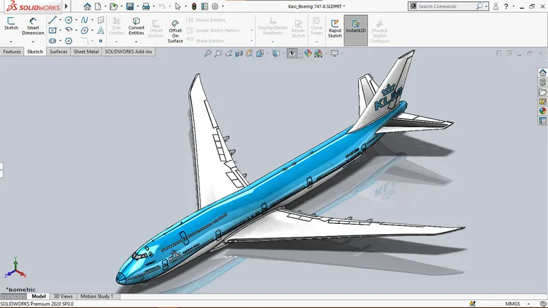
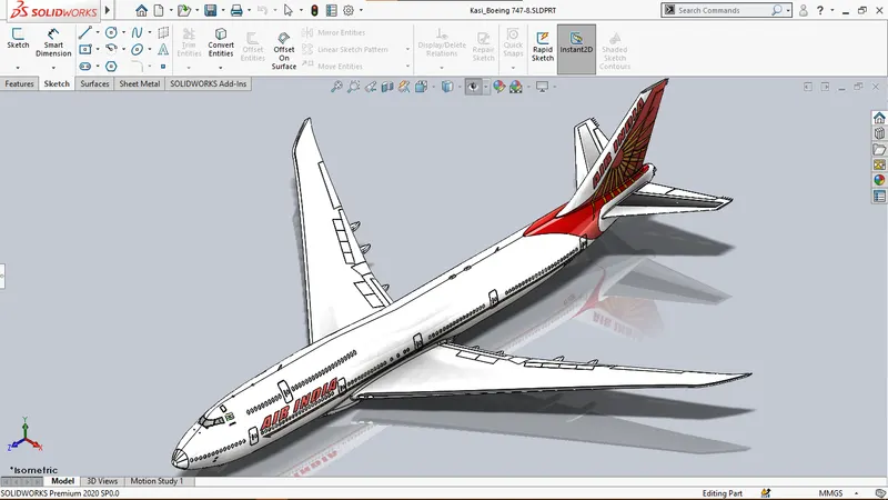
Fig. Isometric View of Main Body for both configurations of KLM and Air India.
2. Engine:
The Boeing 747-8 has four General Electric GEnx-2B67 turbofan jet engines, two located on each wing. It is an advanced dual rotor, axial flow, high-bypass turbofan jet engine in production by GE Aviation for the Boeing 747 and Boeing 747-8 airliners. Its design is derived from GE90 engine and to reduce weight, it features 18 composite fan blades, a composite fan case and titanium aluminide stage 6 and 7 low-pressure turbine blades. It has a 10-stage high-pressure compressor and is quieter, helped by larger and more efficient fan blades.
Sketch tools and Features used in modelling Engine:
- Sketch
- Sketch Picture
- Line
- Spline
- Centerline
- Smart Dimension
- Revolved Boss/Base
- Circle
- Extruded Cut
- Split
- Fillet
- Shell
- Split Line
- Reference Geometry
- Circular Pattern
- Lofted Surface
- Trim Surface
- Thicken
- Chamfer
- Revolved Surface
- Convert Entities
- Offset Entities
- Extruded Boss/Base
- Draft
- Revolved Cut
- Combine
- Variable fillet
- Add Appearance
- Edit Appearance
The new features used in modelling the Engine are explained below:
- Circular Pattern: It is used to duplicate a face or a body or a feature about a specified axis with defined angular distance and number of instances.
- Lofted Surface: It is used to create a lofted surface between two or more profiles or sketches along some specified guide curves.
- Trim Surface: It is used to trim where a surface intersects with another surface or a plane or a sketch.
- Revolved Surface: It is used to revolve a sketch or selected sketch contours around an axis to create a surface feature.
- Revolved Cut: It is used to cut a solid model by revolving a sketch profile around an axis.
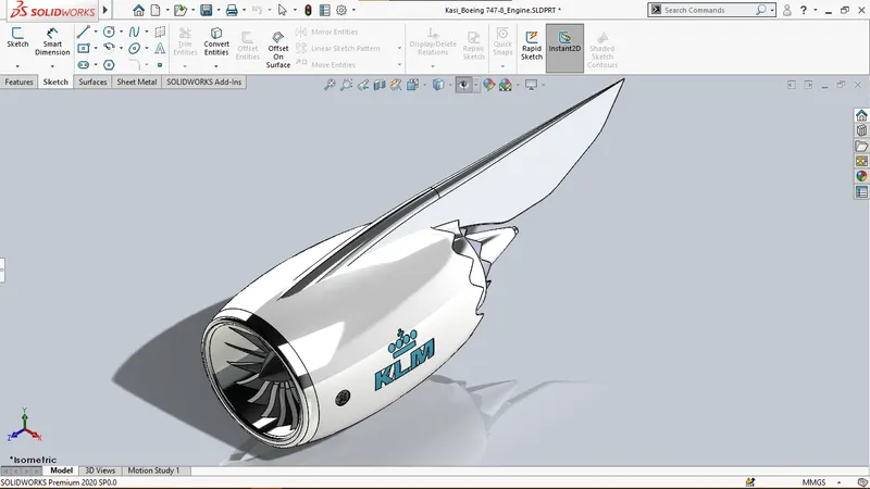
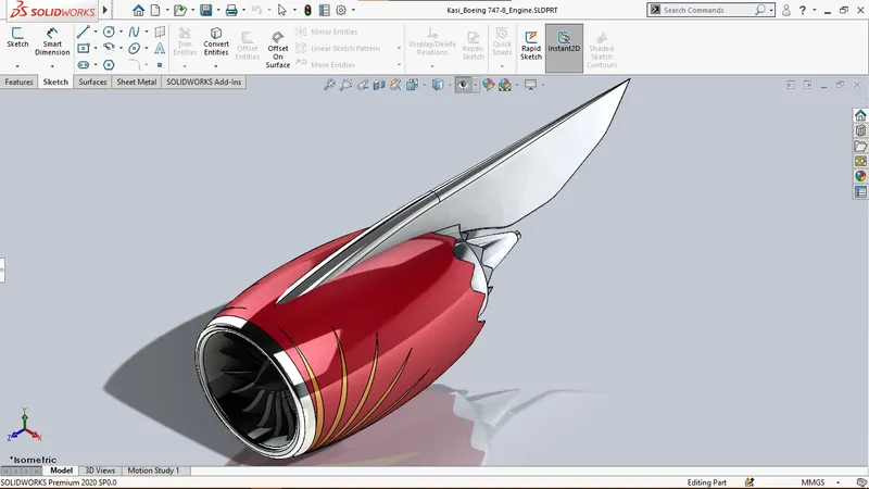
Fig. Isometric View of Engine for both configurations of KLM and Air India
3. Nose Gear Assembly:
The Nose Gear Assembly of Boeing 747-8 is retractable and located at the forward end of the fuselage. It bears the forward weight of the aircraft and constitutes the following components:
- Nose Gear Base:
Sketch tools and Features used in modelling Nose Gear Base:- Sketch
- Circle
- Extruded Boss/Base
- Fillet
- Centerline
- Point
- Convert Entities
- Offset Entities
- Linear Pattern
- Slot
- Mirror
- Combine
- Center Rectangle
- Chamfer
- Dome
- Split Line
- Extruded Cut
- Circular Pattern
- Swept Boss/Base
- Move Face
- Add Appearance
- Edit Appearance
- Nose Gear Suspension Arm:
New Sketch tools and Features used in modelling Nose Gear Suspension Arm:- Trim Entities
- Wheel:
New Sketch tools and Features used in modelling Wheel:- Reference Geometry
- Center Rectangle
- Centerpoint Arc
- Revolved Cut
- Shell
- Spline
- Polygon
The new features used in modelling the Nose Gear Assembly are explained below:
- Move Face: It is used to move a selected face or faces along a specified direction.
- Polygon: It is used to create a polygon with specified number of faces in a sketch.
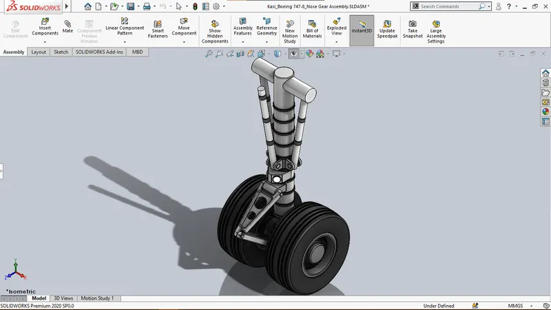
Fig. Isometric View of Nose Gear Assembly.
4. Main Gear Assembly:
Boeing 747-8 has a set of four Main Landing Gears positioned at the middle of the fuselage, two of which are positioned to the main body on either side and other two are located on each wing. Each Main Gear Assembly constitutes the following parts:
- Main Gear Base:
Sketch tools and Features used in modelling Nose Gear Base:- Sketch
- Circle
- Extruded Boss/Base
- Centerline
- Fillet
- Circular Pattern
- Polygon
- Extruded Cut
- Combine
- Convert Entities
- Offset Entities
- Linear Pattern
- Mirror
- Center Rectangle
- Swept Boss/Base
- Slot
- Reference Geometry
- Line
- Chamfer
- Add Appearance
- Edit Appearance
- Main Gear Suspension Arm:
New Sketch tools and Features used in modelling Nose Gear Suspension Arm:- Trim Entities
- Corner Rectangle
- Wheel
The new features used in modelling the Main Gear Assembly are explained below:
- Corner Rectangle: It is used to create a rectangle by specifying two opposite corners.
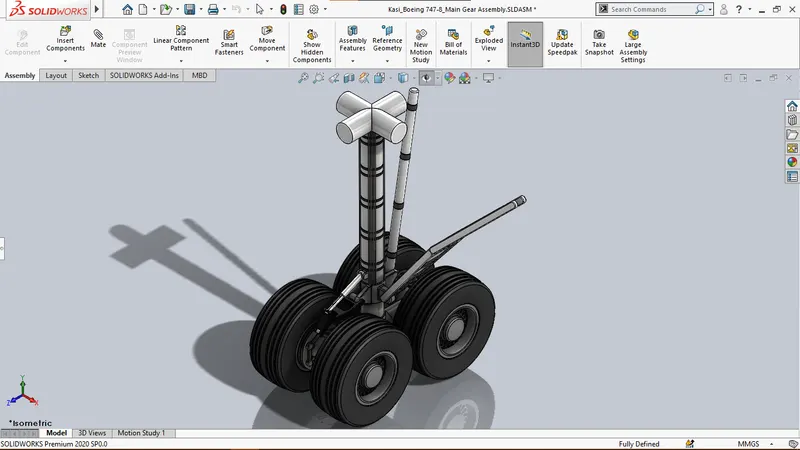
Fig. Isometric View of Main Gear Assembly.
ASSEMBLY OF Boeing 747-8:
The components are assembled together by importing them into the assembly file and applying mates to them in a proper order.
The different mates used during the assembly of Boeing 747-8 are as follows:
- Distance Mate
- Coincident Mate
- Parallel Mate
- Advanced Mechanical Mate (Gear Mate)
- Concentric Mate
Some of the components are patterned and mirrored as per requirement using the following commands:
- Linear Component Pattern
- Mirror Component
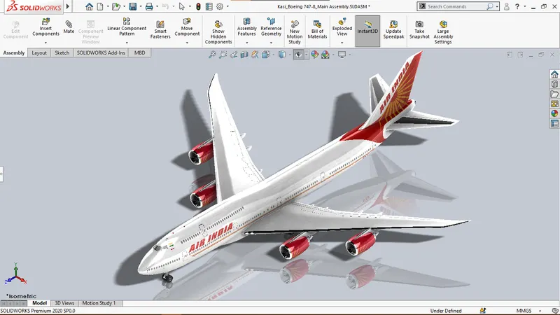
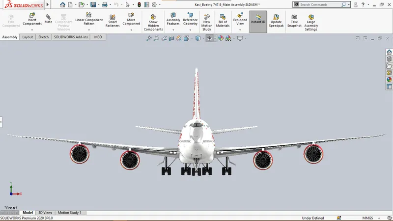
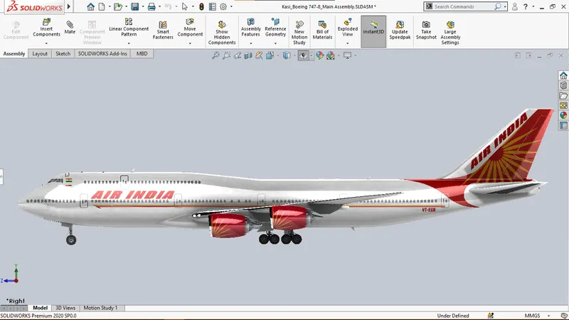
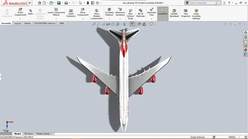
Images of Boeing 747-8 Assemblies in both KLM and Air India liveries enabling Realview Graphics are shown below
| KLM Livery | Air India Livery | |
| Isometric View | 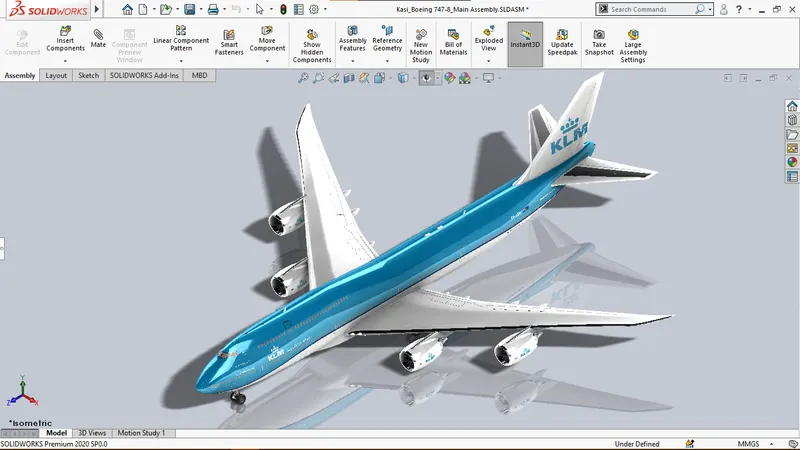 |
 |
| Front View | 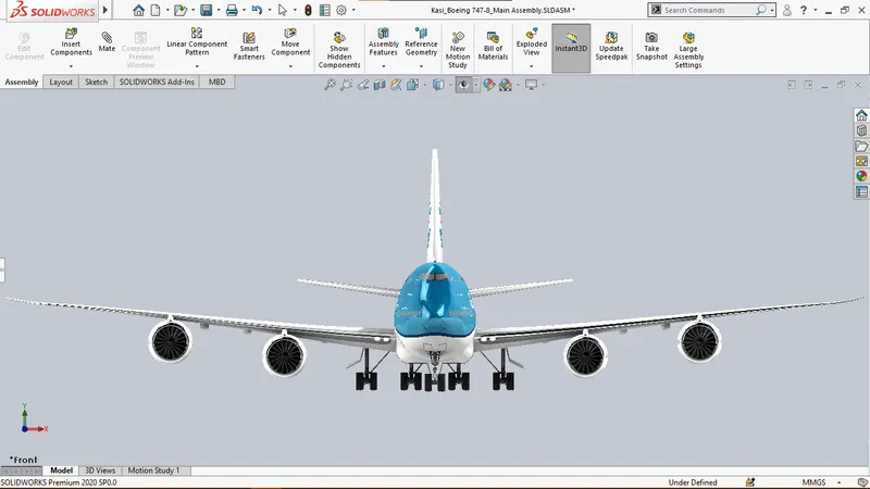 |
 |
| Side View | 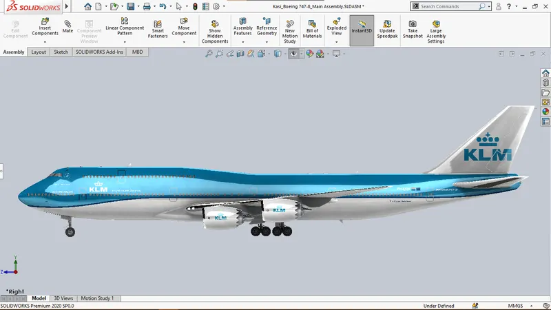 |
 |
| Top View | 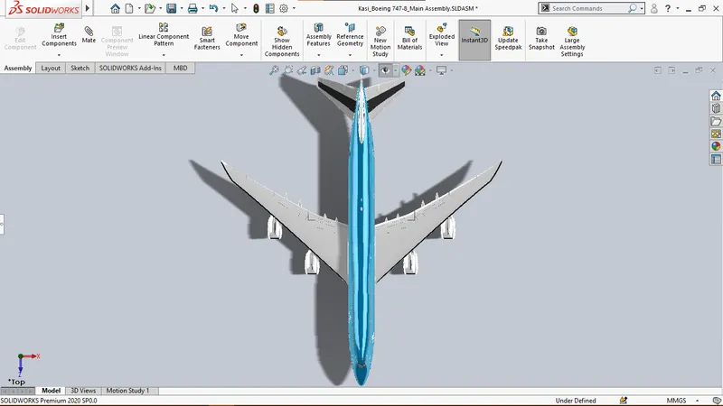 |
 |
Rendering:
Rendering is the process of generating photorealistic images from a computer software including either 2D or 3D models. The output is referred to as a rendered image or simply a render.
SolidWorks has add-ins such as Photoview 360 which can create renders within the software, but SolidWorks Visualize is a dedicated application with powerful tools for creating photorealistic renders of products.
The following images are the renders of Boeing 747-8 with different configurations in terms of Material Appearances, Background Environment and Camera specifications.
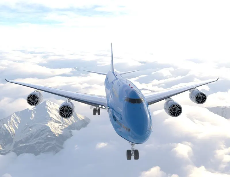
Fig. Photorealistic render of Boeing 747-8 with 35mm lens
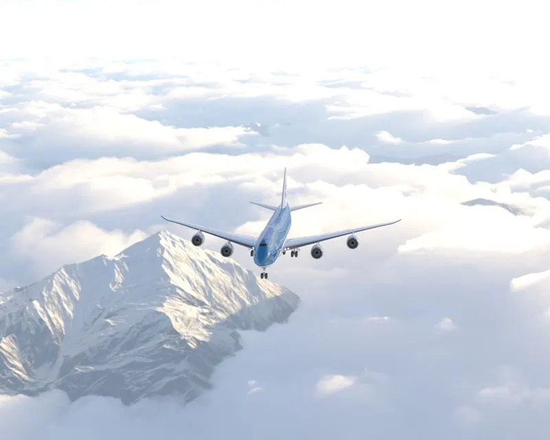
Fig. Photorealistic render of Boeing 747-8 with Telephoto 200mm lens
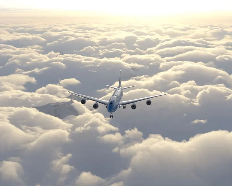
Fig. Photorealistic render of Boeing 747-8 with Telephoto 200mm lens
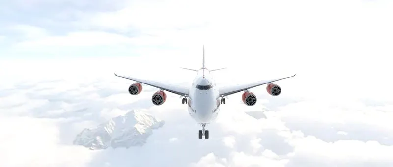
Fig. Photorealistic render of Boeing 747-8 with panoramic lens
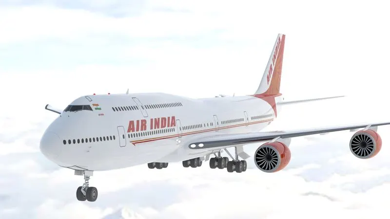
Fig. Photorealistic render of Boeing 747-8 with Telephoto 200mm lens
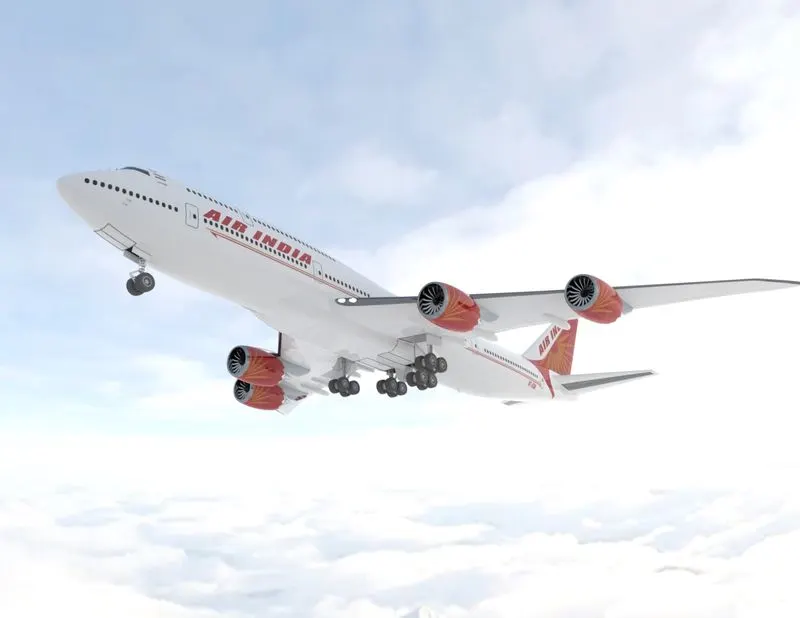
Fig. Photorealistic render of Boeing 747-8 with 35mm lens
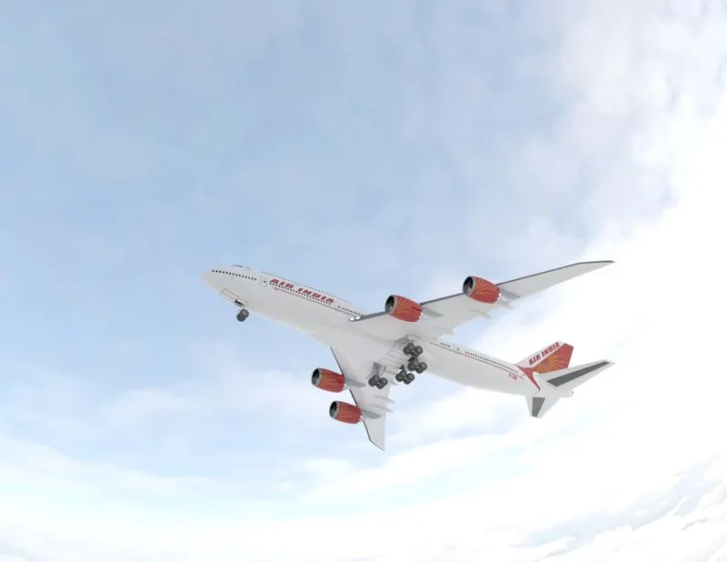
Fig. Photorealistic render of Boeing 747-8 with 35mm lens
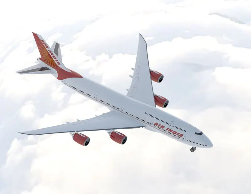
Fig. Photorealistic render of Boeing 747-8 with 35mm lens
Conclusion:
Hence the objectives have been met with the completion of Assembly of Boeing 747-8 in SolidWorks and Photorealistic rendering in SolidWorks Visualize. The project outcomes are as follows:
- Part Modelling, Surface Modelling and Assembly of different components in SolidWorks
- Setting up the Assembly in different environments with different appearances, decals, cameras and lights in SolidWorks
- Photorealistic Rendering of the assembly with different configurations in SolidWorks Visualize