Bird Strike in Aero Engine simulation using LS-DYNA
OBJECTIVE:
- To perform a Bird Strike in Aero Engine simulation using LS-DYNA.
- To follow a consistent numbering approach 100000+ for nodes, 500000+ for elements, and 1000+ for the parts and to keep all the other keywords numbered within 10000-19999 while following a range for each one.
- To create the main file referencing all the input files for the parts, contacts, boundary conditions, materials and control cards.
GIVEN MODEL:
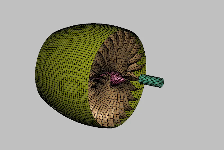
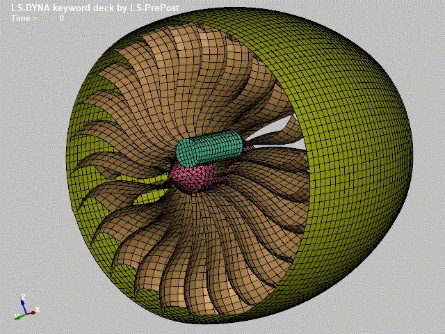
The given model contains 4 parts namely, the hub, the blades, the engine casing and the bird.
PROCEDURE:
- First, all the parts are separated into different parts files.
- The part, node and element ids are changed using the renumber tool.
- Separate files are created for defining the material properties, contacts, boundary conditions, control cards and etc.,
- All files are included in the main file using the INCLUDE keyword.
- The termination time is set to 5ms
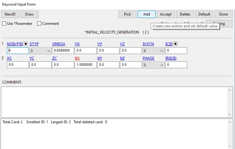
- An initial angular velocity of 6000 rpm is defined on the blades.
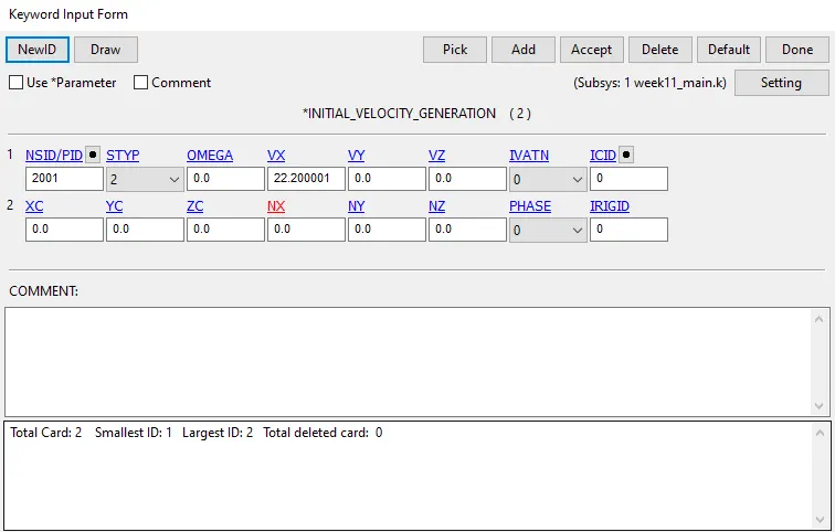
- An initial velocity of 80 km/hr is defined on the bird model
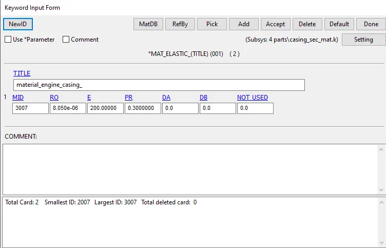
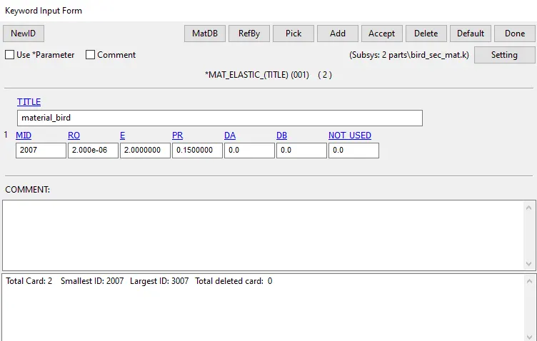
MATERIALS CARD:
Blades:
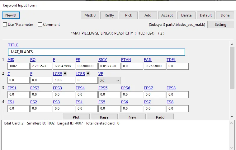
The thickness defined on the blades is 5mm.
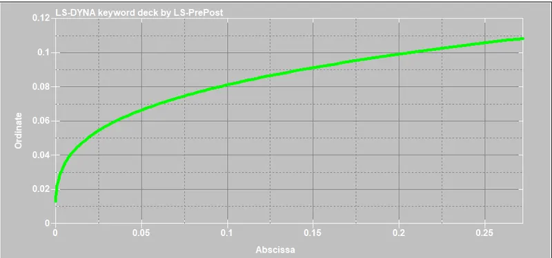
Effective Stress vs effective plastic strain curve of the blade's material:
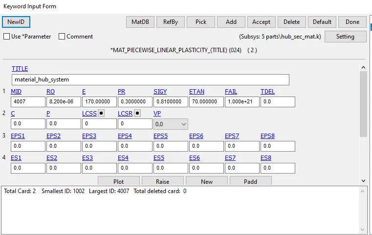
Hub:
Engine casing:
Bird:
CONTACTS DEFINED:
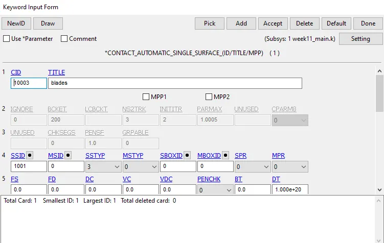
Contact between blades:
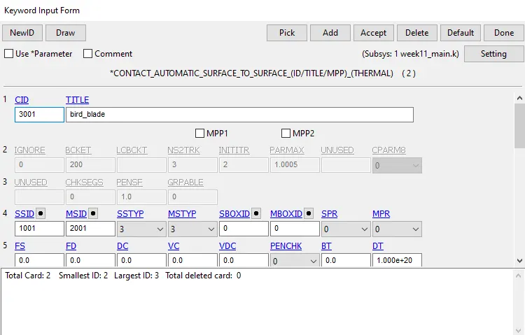
Contact between blades and the bird model:
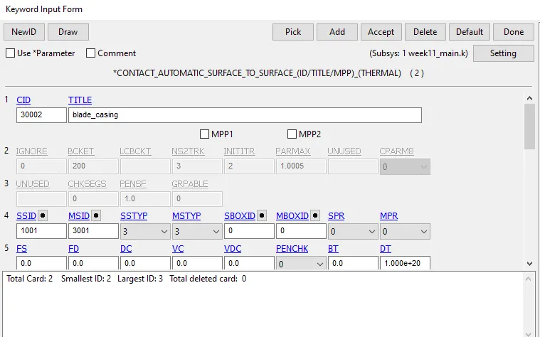
Contacts between blades and the engine casing:
BOUNDARY CONDITIONS:
The initial velocity of the blades:
An initial angular velocity of 6000rpm is defined on the blades around the x-axis.
An initial velocity of 80km/hr is defined on the bird model.
The engine casing is kept fixed.
The blades are connected to the hub through Constraint Nodal Rigid Body connections.
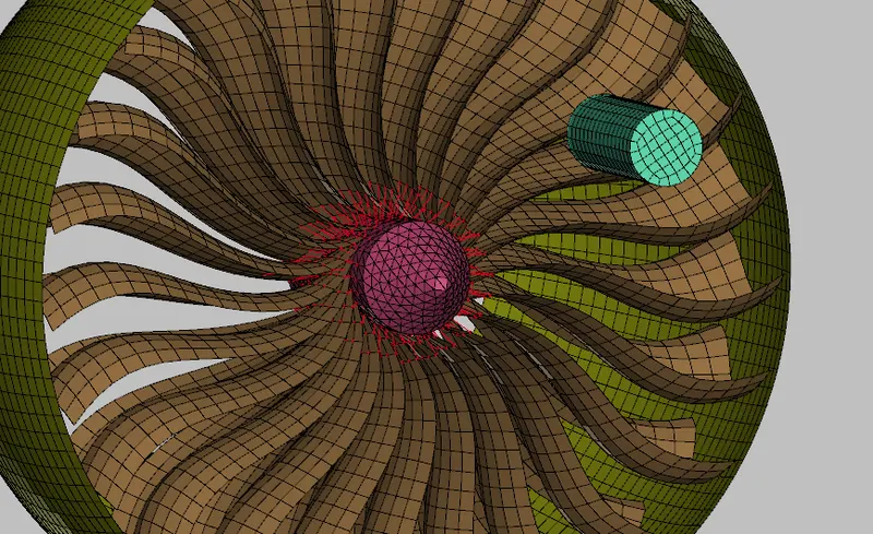
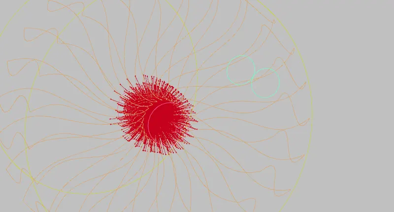
The translation of the hub model around the x-axis is constrained.
The termination time is set to 5ms.
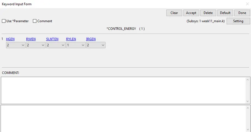
CONTROL ENERGY :
HGEN is set to 2 in order to compute the hourglass energy.
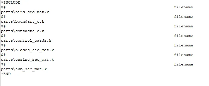
The boundary conditions, material and part data, contacts and control cards are saved as separate files.
The INCLUDE keyword is used in the main file to input the material data, parts, boundary conditions, contacts and control cards.
MASS SCALING:
CASE 1: DT2MS = -3.5E-5 AND TSSFAC=0.9
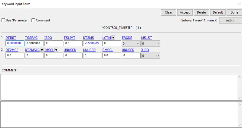
The estimated completion time is 59 mins and the percentage of mass added is 0.
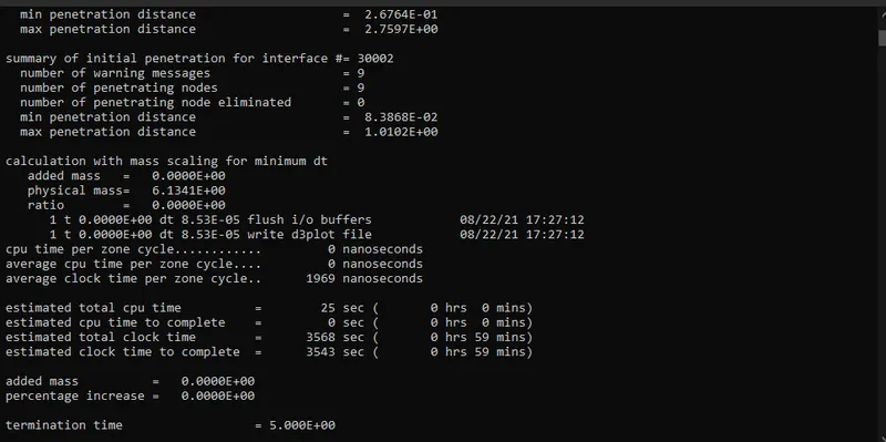
CASE 2: DT2MS = -3.5E-4 AND TSSFAC=0.9:
The estimated completion time is 10 mins and the percentage of mass added is 4.41%.
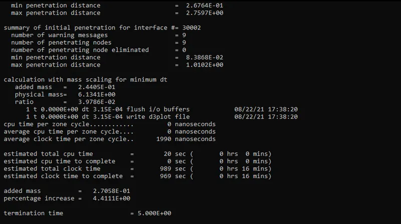
In-order keep the percentage of added mass below 5%, DT2MS is set to -3.5e-4.
RESULTS:
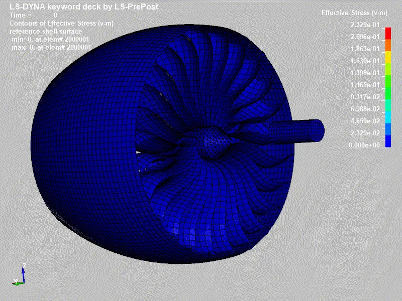
EFFECTIVE STRESS:
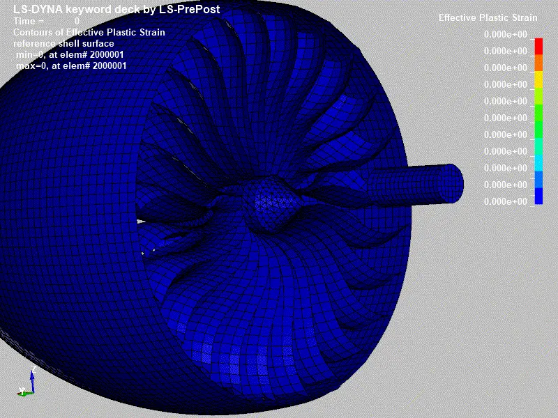
EFFECTIVE PLASTIC STRAIN:
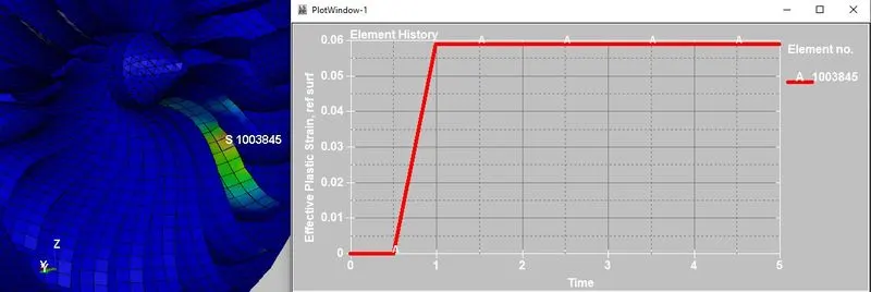
MAXIMUM PLASTIC STRAIN:
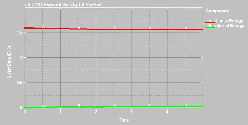
INTERNAL ENERGY AND KINETIC ENERGY:
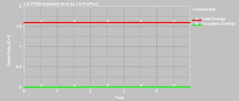
TOTAL ENERGY AND HOURGLASS ENERGY:
CONCLUSION:
- There is hourglass energy generated in the model.
- As expected the internal energy increases and the kinetic energy drops.
- The maximum effective plastic strain generated at the area of impact is 0.06.
- Since the thickness of the blade is 5 mm, It withstood the impact without much deformation.