Bird Strike - Project - 2
Assignment 12
1.Introduction
This assignment is dedicated to the analysis of a bird strike impact on a plane engine.
2. Procedure
In this assignment, the complexities in the model will be added one by one, to avoid complex bugs close to the end of the simulation setup.
The following items will be carried sequentially throughout the assignment:
- Separating model bodies into individual files
- Assemble the individual files with resort to the *INCLUDE keyword
- Define materials for each part
- Define blade rotation
- Define simulation controls
- Run simulation
- Check if the materials properties are correctly defined and the unit consistency
- Check the value of the time step
- Define constraints for engine case
- Define contacts
- Define initial velocity for the bird
- Run simulation
- Check if the simulation duration is appropriate
- Updade engine rotation and bird velocity if necessary
- Check material deformation
- Add material failure criteria
- Run simulation
- Compare results with the simulation with no failure criteria.
- Draw conclusions
- Run simulation
- Run simulation
- Run simulation
2.1. Component organization
The following table contains the Element ID of the elements of each of the meshed components:
|
Component |
Element ID |
Node ID |
|
Bird |
64184:64993 |
43214:44007 |
|
EngineCase |
5547: 11938 |
7633: 43218 |
|
EngineCenter |
1: 63143 |
11762: 43218 |
|
Blades |
11952: 46525 |
11729: 43218 |
A MatLab program could have been developed to better organize the Node and Elements IDs.
The following images demonstrate the separated components considered in the previous table.
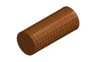
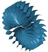
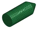
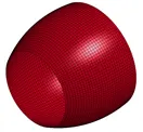
Bird.k Blades.k EngineCenter.k EngineCase.k
2.2. Materials file
A separate file was created to define the materials.
The elastic constants used to define the steel material are:
|
Property [units] |
Value |
|
Young’s Moduls [Pa] |
1000 |
|
Density [Kg/] |
7800 |
|
Poisson Coefficient |
0.3 |
The materials file also contains the sections. 2 sections were created: one shell and one solid.
Shell section: ELFORM = 2
Solid section: ELFORM = 1 (Constant stress solid)
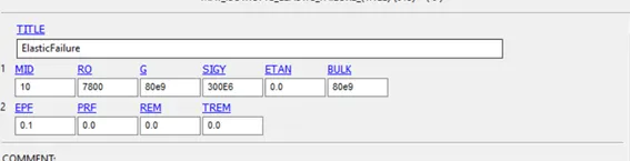
The failure was introduced in the model by means of *MAT_ISOTROPIC_ELASTIC_FAILURE. This model is a simple failure formulation in which the following values are used:
2.3. Constraints and contacts file
Although the Constrains and Contacts were applied in the GlobalModel file, they were saved in a separate file (ConsContact.k).
2.3.1. Constraints of the model
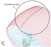
To constrain the model, the top nodes (maximum y coordinate) were constrained in all degrees of freedom, simulating the connection between the engine and the wing, as seen in the figure below

2.3.2. Imposed velocities
Overall, two imposed velocities will be applied to the model. One to make the engine center (and consequently, the blades) rotate; and another one to make the bird hit the blades.
To make the engine center (green body) rotate, a node will be created at the averaged center of this part. This node will then be connected to all of the nodes of this part by means of a constrained rigid body. The blades will spin at speed of 10 rad/s.
The bird hits the engine at 50 m/s.
2.4. Simulation setup
The simulation time was set to 0.2 s. An explicit solver was used.
3. Results
It was not possible to apply the material model that considers the failure because this material type is not supported by Quadrileteral elements, which resulted in an error in the solver.
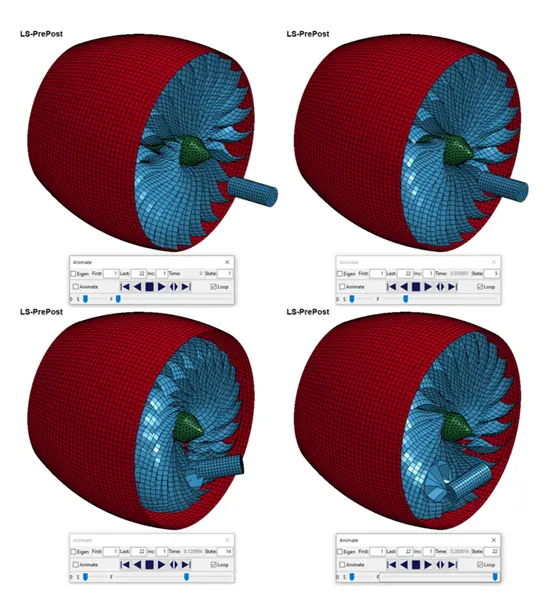
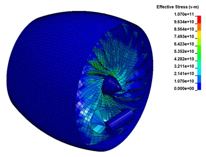
The model without failure took 2 minutes to run and the following figures demonstrate a few screenshots of the simulation.
4. Conclusion
As seen in the images above, the deformation of some elements in the blades is too excessive to be considered realistic, which could have been avoided by implementing the failure model.
The stresses that are verified in the last frame of the simulation are also unrealistically high, due to the same reasons.