Bird Strike - Project - 2
Bird Strike Analysis:
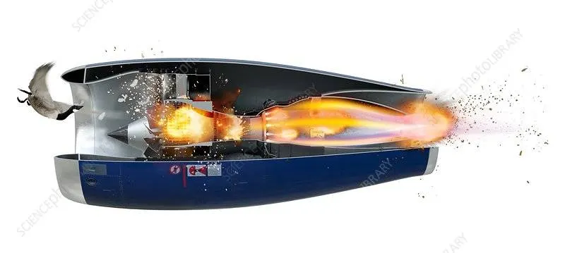
Aim: To understand and demonstrate a bird strike analysis and the use of ‘Include’ keyword for a professional and structured approach.
Objectives:
- Simulate a bird strike situation using given models with appropriate material models as required.
- Establish a numbering system for the Id’s of all the keywords with proper ranges for multiple cards.
- Distribute the given model in individual keyword files for various components as well as analysis sub-components.
- Use the ‘Include’ keyword to put these keyword files together and run the analysis such that moving the folder with these files won’t cause a problem with the analysis.
- Use mass scaling to minimise the analysis time and its effect on the outputs.
Bird strike analysis:
- Bird strike is a commonly occurring scenario where a bird accidently comes in contact with a plane, a jet engine on a commercial plane, or even small propeller planes and helicopters. This usually happens during the landing or take-off but isn’t limited to them. Even though a bird is a light projectile with low density and doesn’t pose much danger in stationary condition, during flight or when the plane is in motion at comparatively high speeds, things can go south. In many cases, even a small bird is capable of bringing down a commercial plane if it hits any crucial component on the plane essentially making the onboard crew and systems to lose control and crash. One such crucial part is the turbojet engines which are placed under the wings of a plane.
- The compressor blades and guide vanes suck in the ambient air, pressurise it and then combust it in the combustion chamber to produce thrust which pushes the plane forward. These blades are usually open to the surroundings and are carefully designed to survive such an accident and still operate. Moreover there are various redundancy protocols in an airplane with backups and emergency systems to counter any such incidents but in past when there were none, bird strike was a significant problem and still is.
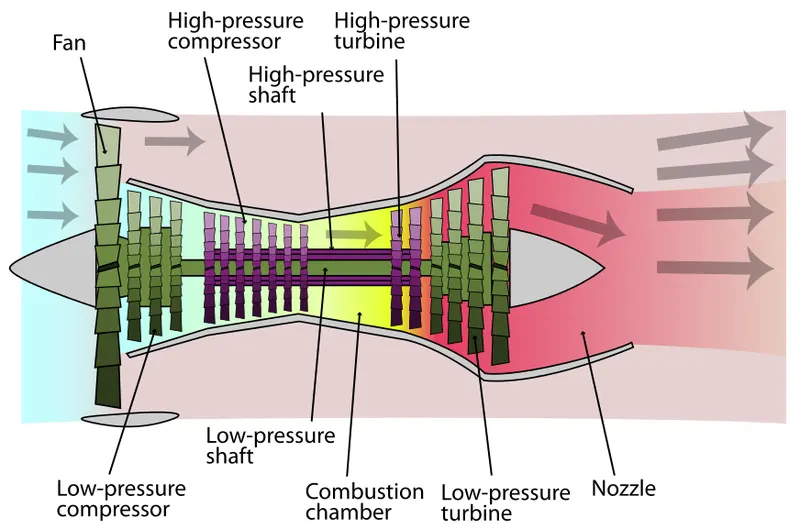
- These regulated blades are usually made of titanium alloys which are machined to accuracy and strong enough to operate safely even after such a incident. The blade ‘slices’ the bird due to its rotation and angle of attack and the remains of the bird are thrown out into a bypass before reaching the combustion chamber preventing any damage to the engine. The remains then leave the engine along with the extra air into the exhaust.
- The turbojet engine manufacturers are required to not only perform simulations and virtual test but also physical validation tests using chicken or other similar meat propelled towards a rotating blade due to regulations. The manufacturers also need to simulate and transfer the result data with airframe manufacturers which build the plane which is to use the engines to make sure of the compliance. There are various regulation s which make sure a jet engine is tested for a bird strike scenario and can tackle it in real life.
- Bird strike like crash analysis in cars is highly non-linear and transient simulation, where various non-linearity are involved with the results depending on the angular velocity of the rotating blades, velocity of the bird and also the angle of impact.
- Usually for such an analysis advanced techniques like Smooth particle hydrodynamics (SPH) are used for the bird model as at high speeds the bird acts as a volume of water with some air pockets as it is 90% water with hollow bones and soft muscles in the first place, along with a detailed model for the turbofan jet engine generally consisting millions of elements.
- Since our goal is to understand the process and the need of such an analysis the results are irrelevant and the models are simplified.
Analysis setup:
As mentioned the models are very simple and mostly used as dummies for the test. The jet engine components – the casing and the rotating blades are meshed using 2D elements and the hub is meshed with 3D elements. This is a very simplified version of what the engine manufacturers do, with all 3D meshes and accurate models. The bird model is also meshed in 2D mesh and no SPH model is used.
The blade is rigidly mounted with the hub using ‘tied’ contacts and gives an initial angular velocity to rotate them. The hub however is given a prescribed velocity to simulate the driven nature and to see if the blades slow down after the impact. The engine casing is fixed in all DOFs and the bird model is projected towards the blade at about 100m/s speed using ‘prescribed motion’ boundary condition. The contacts are established between the bird model and the blades as well as a self contact for the blades to simulate the blades failure. The necessary outputs are requested to make sure the analysis is done right.
As the blades are not modelled accurately anyway, the thickness of the sections is kept minimum to prevent any instabilities. It is eminent that the blades will fail which is not the actual case but is informative.
Another case is then run using a SPH or smoothed particle hydrodynamic model for the bird for demonstration purpose after referring to some material available online.
The unit system maintained is [kg-mm-ms-kN-GPa]
Procedure:
- The given model consisting of all the components is first distributed into individual component keyword file by simply deleting the rest of the components except one and saving it with unique file name.
- Now to make things easier, these individual component files are edited by adding the respective section card as well as a node set as per requirement for say boundary condition, output request, contact etc.
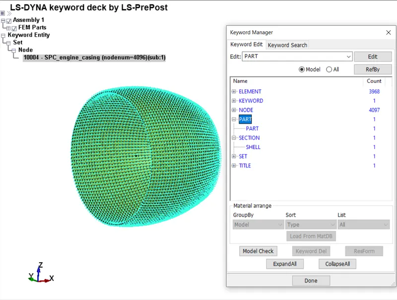
a. Containment/engine casing with constrained node set:
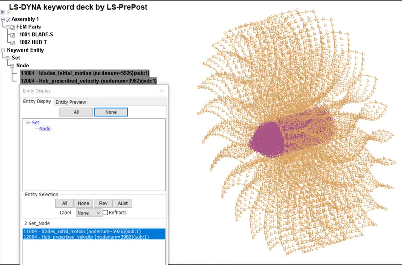
b. Blade and hub component file with node sets of each of their boundary condition – Initial velocity for blades, prescribed velocity for the hub:
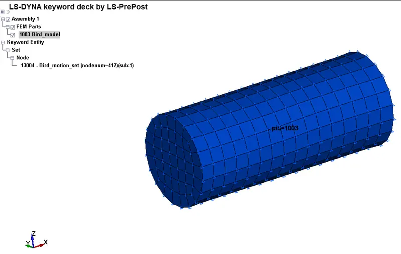
c. 2D bird model with node set for prescribed motion boundary condition:
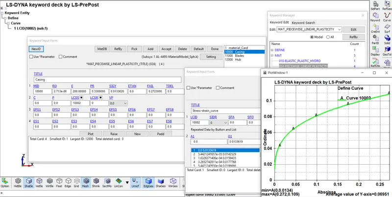
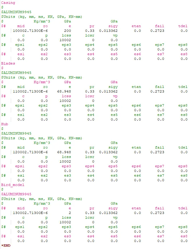
- A separate material keyword file is formed with the required value for the ‘Young’s modulus’ figure in GPa’s . To make it easier, multiple cards are defined in this file as per the component which can be called upon in the part keyword. Smaller elastic modulus for the bird model suggests softer muscles like structure.
Materials keyword file:
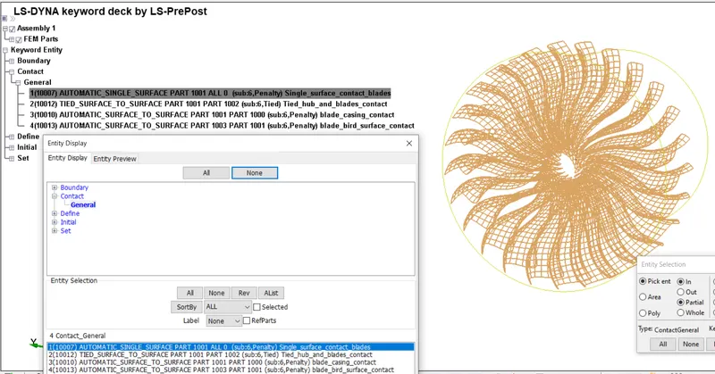
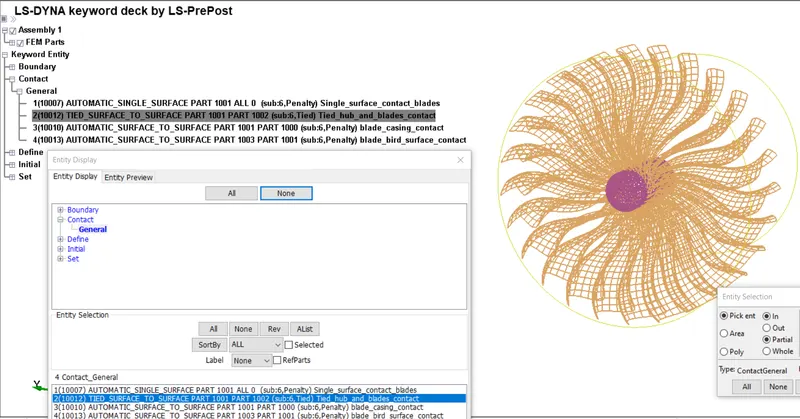
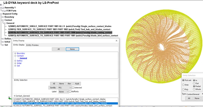
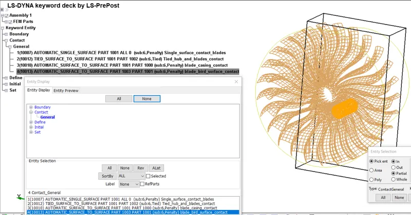
- Now, the contacts are defined using the ‘automatic surface to surface’ contact card with the part Ids being used for the slave and master segment. A ‘tied’ contact is used for the rigid contact between the blades and hub. After initial dummy runs, additional contacts can be added as per observations – e.g. a contact between bird model and engine casing if they are seen to come in contact.
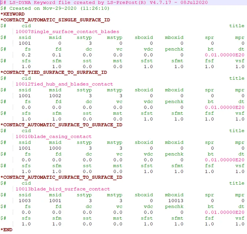
- Single surface contact for the blades
- Tied contact between hub and blades
- Surface to surface contact to keep broken blades from passing straight through casing
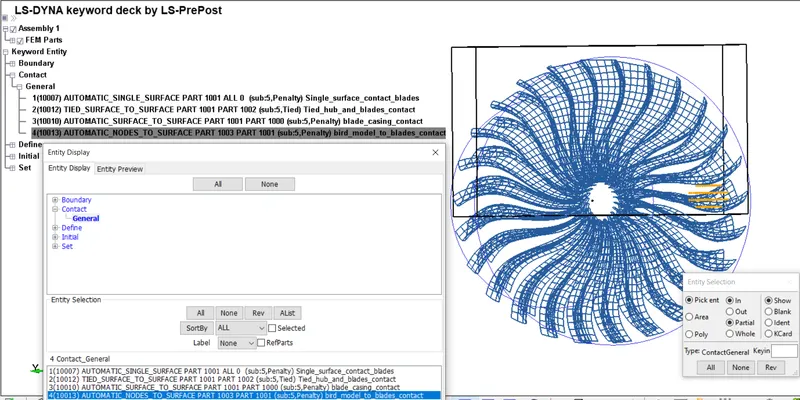
- Surface to surface contact between bird model and the blades for the crash
The master segment box which is defined using co-ordinates narrows down the node count to be considered and helps reducing the already large solution time for such an analysis.
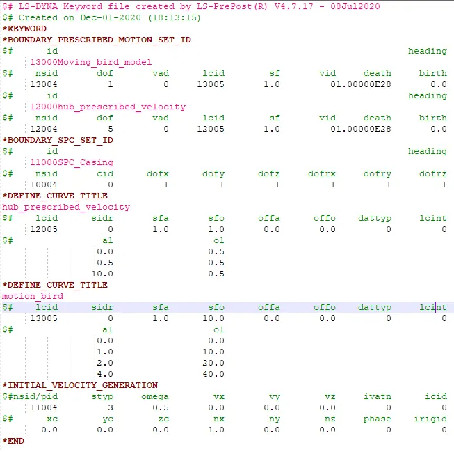
- The boundary conditions for the blades, hub and the bird model are then defined using ‘boundary’ keywords. As mentioned before, the numbers don’t matter as this is a highly simplified model and the results are merely demonstrations hence stability and ease of analysis is prioritised.
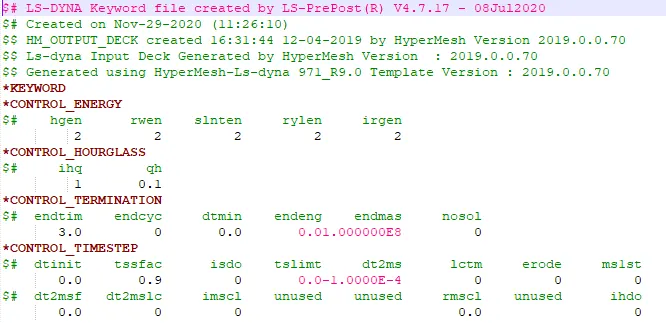
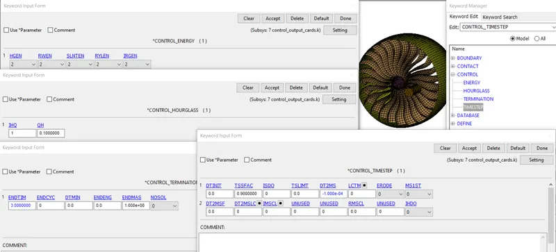
- Now the control cards are defined to apply mass balancing and keep the hourglass energy in check. The analysis termination time, and a request for sliding interface and hourglass energy calculation is also defined in the control card.
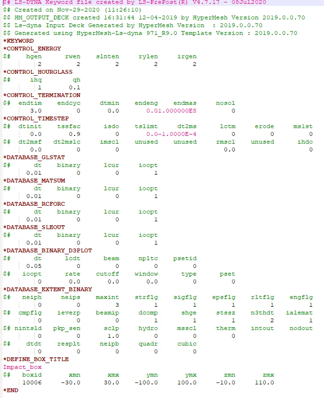
- The last keyword file in the list is for the output requests using database card. As mentioned earlier, this is but a demonstration analysis, hence only the essential outputs such as the global and material energies, sliding and contact interface energies through ASCII cards and d3plot files for animations are requested.
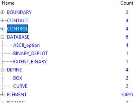
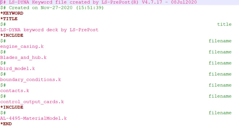
- Finally all these keyword files are combined using ‘include’ keyword in which it is essential to keep all these files in the same folder such that the keyword files are ‘included’ and moving the complete folder won’t cause any problems with the analysis.
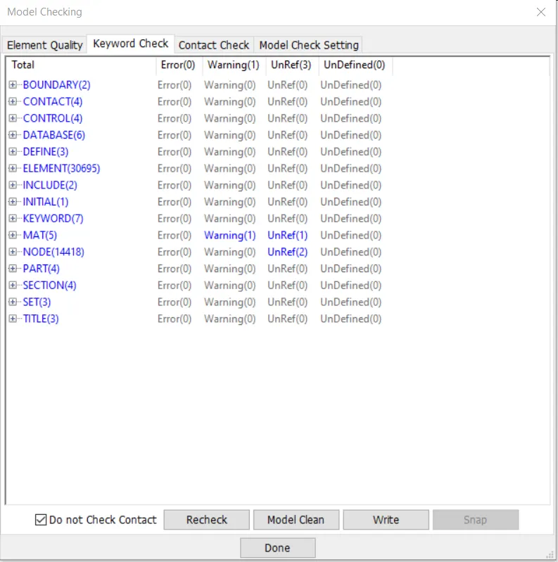
- Finally the solver deck is checked for any errors or warnings using ‘model checking’ – ‘keyword check’ option and the minor errors and warnings are resolved.
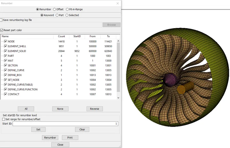
- Now using the ‘renumber’ option, the required changes were done in the ‘ID’s such that a range is established as per the parts so that only from ID of a card, we can figure out which component it belongs to. For example section card with ID-12001 belongs to part 1002, contact card with ID – 10013 contains the parts with IDs 1001 and 1003 and so on.
This technique helps out when there are a number of components coming from different sources and need to be combined into one assembly to be used for a system level analysis and hence is practiced in industries.
- The analysis is the run and the results are post processed to validate the correctness of the simulation. In the second case as an extra, an SPH model is used instead of a 2D model for the bird –which is usually how it is done at the manufacturers end for the reasons mentioned before. The material model as well as the contact definition differs for this model.
- For the 2nd case, using a SPH model which essentially uses nodes as hydrodynamic particle element, the material model was referred from a similar analysis referenced below:
An Elasto-plastic-hydrodynamic material model is used here which also requires a ‘EOS’ or equation of state card which as the name, suggests the thermodynamic state of the material - volumetric deformation (compression or expansion) with respect to pressure. EOS is defined wherever volumetric deformation or strain is comparable with the deviatoric strain, both of which form the stress tensor.
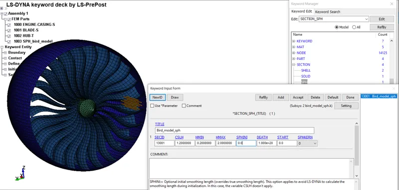
As mentioned before, using this model, the bird is considered as a cluster of fluid particles as a result the section required is different which was selected with default values for the smoothening parameters it comes with.
SPH section with smoothening parameters taken as their default values.
The contact defined between the bird model and blades to cover the interaction is also changed to ‘automatic nodes to surface’ contact.
revised contact keyword file:
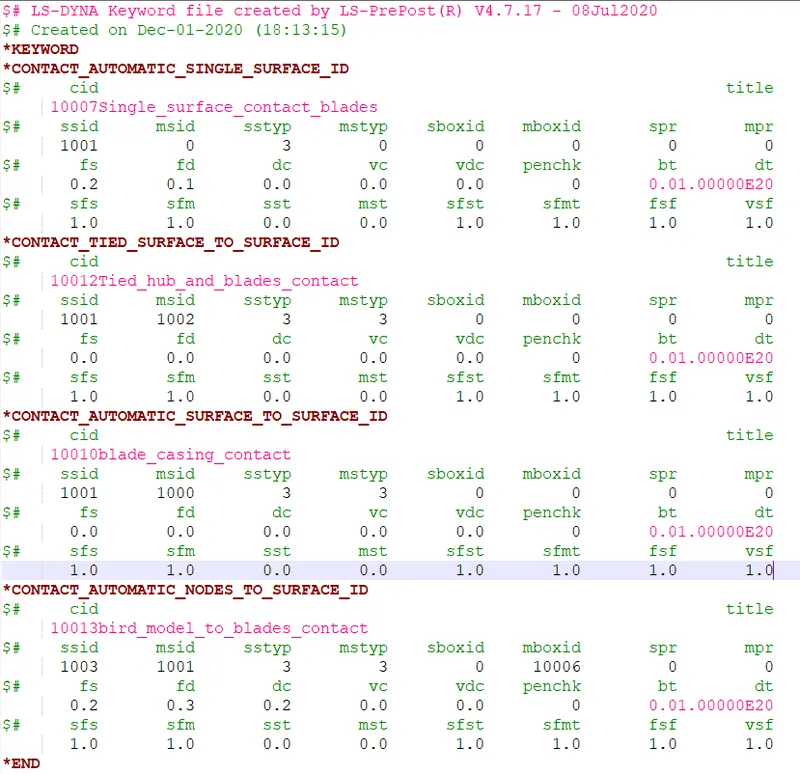
Except these two changes, all other cards remain the same.
Results:
- Case 1: 2D bird model:
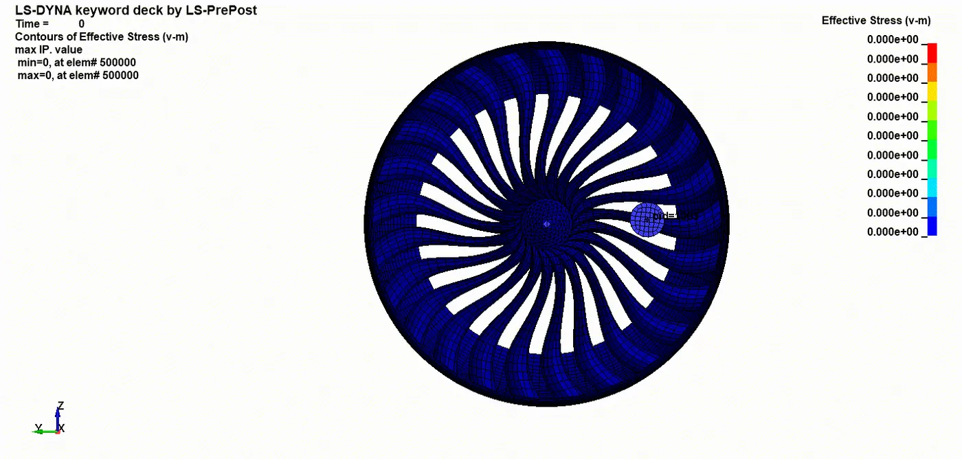
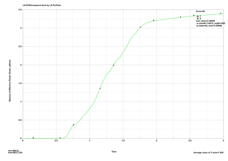
The turbofan blades fail and the elements get deleted as soon as the effective plastic strain reaches the 0.273 or 27% mark as specified in the material model of the blade component.
It can be seen in the animations that the curvature of the blades causes the bird model the move down and outwards from its original trajectory, away from the core, combustion chamber towards the bypass valve.
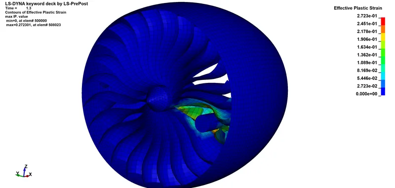
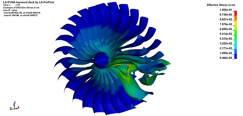
The maximum Von-mises stress recorded comes around 108.2 MPa or 0.1082 GPa.
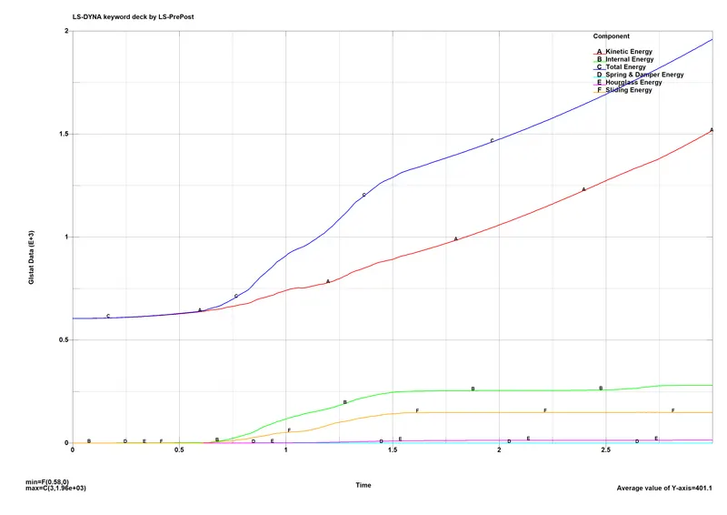
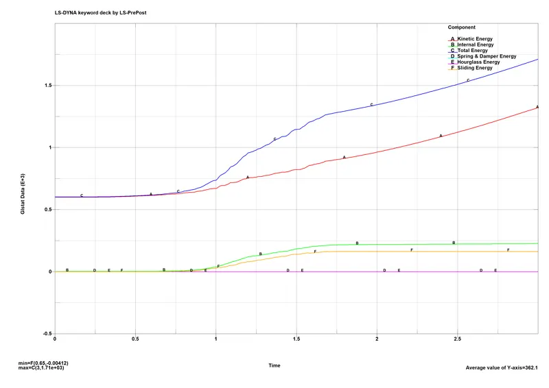
Global energies plot shows little to no hourglass energy and the strain energy or internal energy plot starts climbing as soon as the contact between the bird model and blades occurs and deformation initiates, along with the sliding energy or contact interface energy plot. As the blades are already moving, the kinetic energy plot starts with a y-intercept and goes on increasing as the bird model projectile makes contact with the blades and provides momentum to parts to get moving. Total energy plot which is the sum of all these energies shows clear co-relation which suggests there are no errors and the analysis can be assumed to be correct.
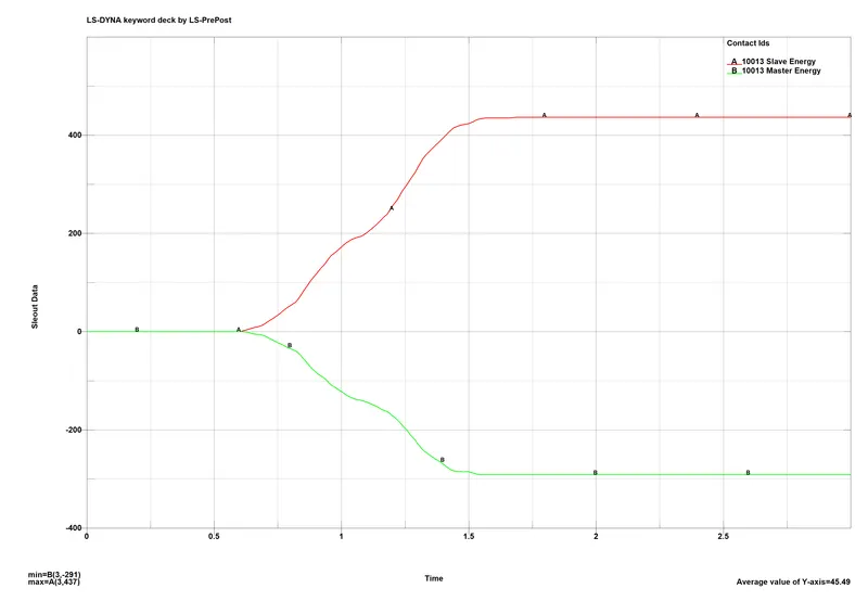
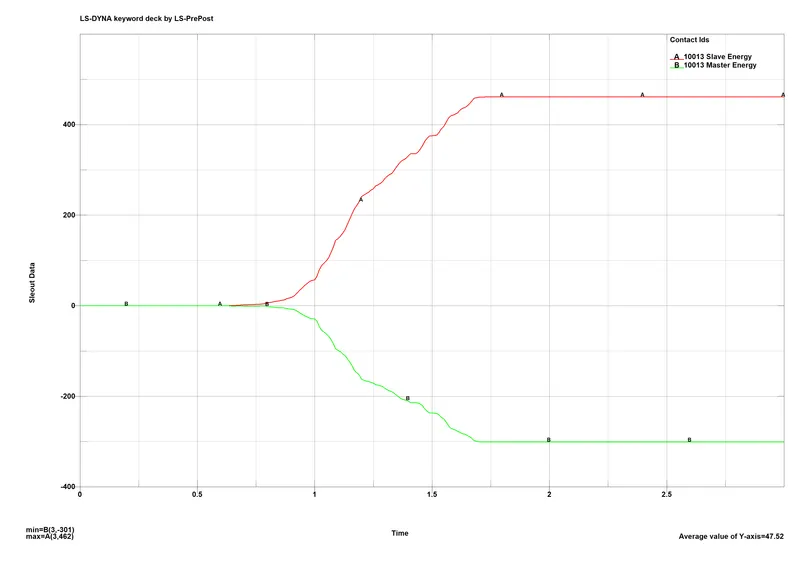
Sliding energy plot shows the absence of any penetrations as the plot only initiates after the contact is established. There is an imbalance in the energies as the slave energy which represents the bird model is higher than the master counterpart since the deformation and internal energy is not large enough to balance out the kinetic energy of the projectile.
- Case 2: SPH bird model:
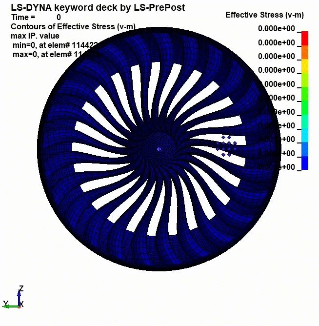
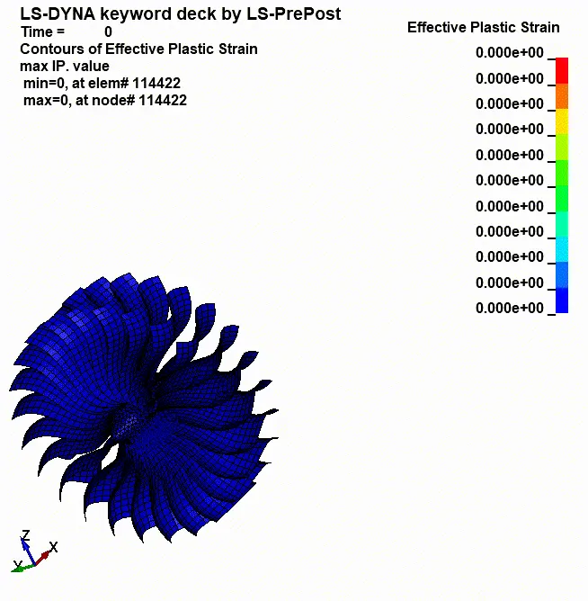
The ‘slicing’ mentioned in the introduction can be seen in this case as the bird model splits into 2-3 smaller ‘pieces’ or clusters as the blades rotate through and channel them outwards.
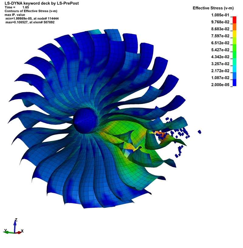
Due to the almost similar material model of the bird, the stress results are very close with minor difference. Again, the blades fail as they reach failure strain and the corresponding elements are deleted.
Von-mises stress:
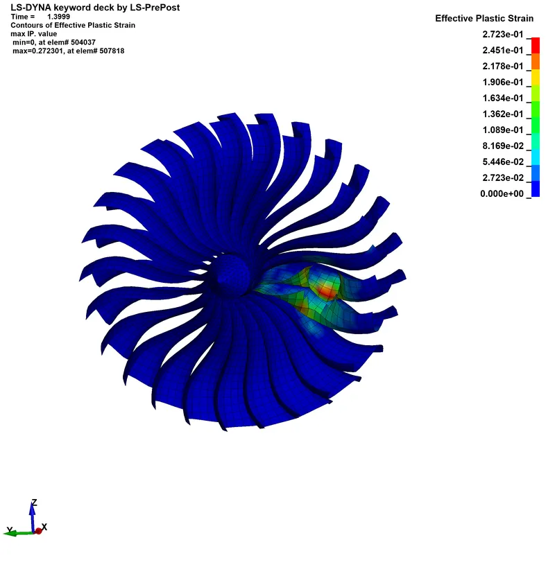
The importance of defining an EOS to take care of the volumetric strains is seen in the plastic strain results which show the splitting of the model with large strain figures.
SPH plastic strain:
Similar to the 1st case, the energy plots co-relate to the analysis timeline and deviate only after the contact is established. The hourglass energy is minimal and the plots make sense hence the results can be assumed to be acceptable.
Sliding or contact interface energy is much more balanced in this case with comparable master and slave energies initiating at the time of impact.
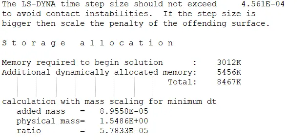
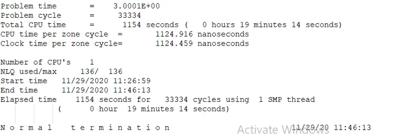
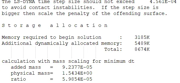
Mass scaling: On initial dummy runs, it was observed that the minimum time step for the simulation which is calculated using critical length and speed of sound in the given medium was around 6.5e-5ms. The total run time for the solution was around 60 minutes. After using the mass scaling option by fixing the minimum time step at 9e-5ms, (TSSFAC is 0.9 for both cases) a very small amount of mass is added to the analysis – around 0.06% and still the run time is reduced to 18 minutes, which can be further reduced.
Case 1:
Total runtime:
Case 2:
Total runtime:
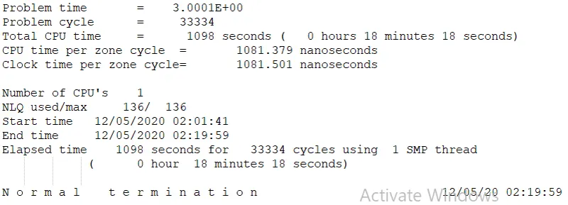
There is no noticeable difference in outputs for both the cases as a result of mass scaling. The time-step can be further increased without significantly increasing the mass upto the usual 8% limit which will reduce the runtime drastically.
Conclusion:
- It is evident from the results and the catastrophic failure observed that this is a demonstration simulation and its purpose is introduction to the bird strike phenomenon and how it is managed. Co-relating the results with physical tests confirms that. The objectives are fulfilled which outline the systematic approach required in complex multi component analysis and the use of mass scaling.
- A much detailed model of the components and material models required to actually perform the analysis as done by the engine manufacturers, to make any judgments. The approach however will be similar. The verification practice of making sure the energy plots are co-relating and make sense, with a minimal hourglassing and no unrealistic deformations and stress, strain figures deems the simulation correct.
- The 2nd case with the SPH model for the bird gives a clear idea how the blades deal with debris and such bird strikes. The curvature of the blades, guide the sliced debris outwards, away from the centre where the combustion chamber and compressor blades are. The outwards channels open to a bypass valve which opens up at the exhaust which prevents the engine failure.
- The impact force of the projectile is seen to be large enough not only to damage a couple of blades while braking one to pieces, but to imbalance the whole assembly triggering a ‘Fan Blade-Out’ situation. Generally the fan is mounted on a shaft with bearings and many other components across the engine so it is highly impossible just as an aftermath of birdstrike. However the most difficult part of engine regulation is the Fan Blade-Out simulation where such a scenario is to be simulated and physically tested to ensure the engine casing contents all the debris and sustains the impacts of blades rubbing inside.