BASE BRACKET CHALLENGE
CLASS-A Surface
- Class A surface refers to those surfaces which are VISIBLE and abide to the physical meaning, in a product.
- Class-A surface means visible surface. It gives the aesthetic of the component which is created by the styling team and gives to the part design engineer to create the part with all engineering aspects.
- Class ‘A’ surfaces are primarily used in the automotive environment and refer to those surfaces which are visible in a product.
- In other words: A - class surfaces are those aesthetic/free-form surfaces, which are visible to us (interior/exterior), and have an optimal aesthetic shape and high surface quality.
CLASS-B Surface
- Class-B surface means the thickness of a part it is not visible and is inside part.
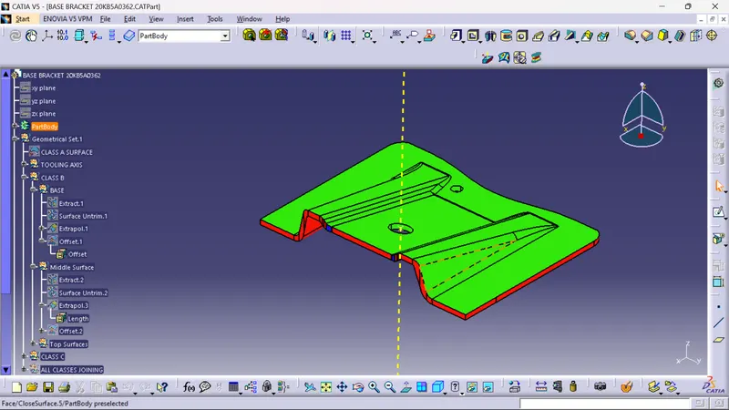
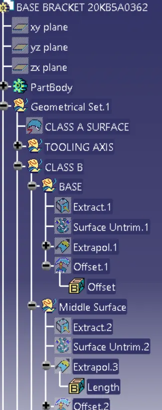
- Class-B surface is created by extracting each walls and un-trimming and extrapolating the walls to obtain the shape by trimming the excess surfaces and offsetting it to certain distance based on the thickness of the model and giving fillets wherever it is necessary. The offset surface will be the B-Surface.
- In other words, the Class-B surface is a surface below a certain thickness from the class-A surface. This is the surface that contains engineering aspects of a model.
CLASS-C Surface
- The surface that joins class-A and class-B surfaces are class-C surfaces. Class C is often specified for interior surfaces not readily visible, surfaces that will be covered by another part when assembled
- Tooling axis: The direction in which the mold or core and cavity opens is the tooling axis.
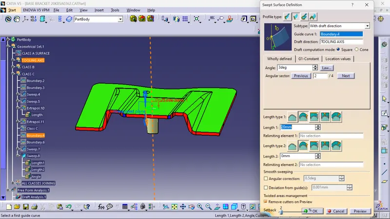
- The surface created using the sweep option by sweeping the boundaries of A-surface along the tooling axis to connect from A to B-surface is called C-Surface.
- The Class C finish allows more imperfections than Class A or B. Class C is often specified for interior surfaces not readily visible, surfaces that will be covered by another part when assembled, or surfaces which the Customer feels do not need to meet a high cosmetic finish.
TOOLING DIRECTION
- In Molding, machine arrangement is given to open the mould along a direction which is known as Tooling Direction.
- In other words. The mould is built from two separate halves (Core and Cavity) and tooling direction basically defines the direction of mould pulls apart.
- Tooling direction is known as primary direction.
FOR TOOLING AXIS:
- Using the tooling axis created along x and y-axis, these tooling axes are used for creation of tooling axis by bisecting method where the two lines and point will be selected as inputs.
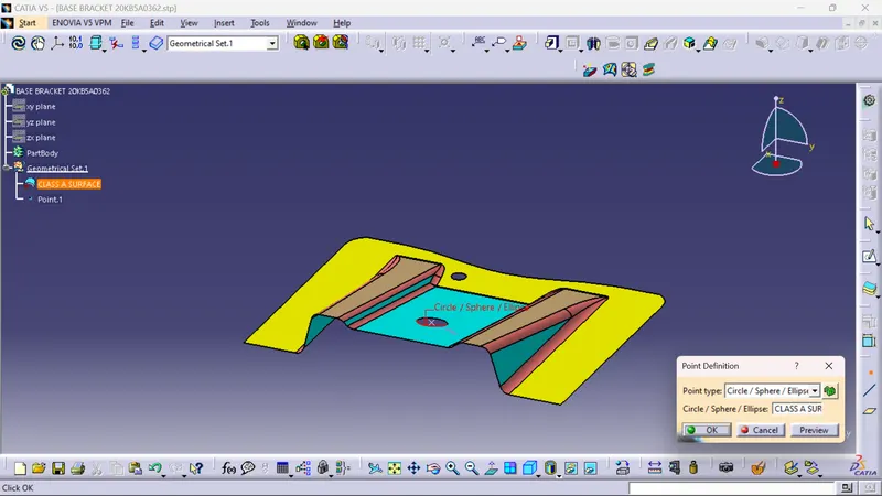
- CREATE POINT WITH THE HELP OF CIRCLE ELIPSE COMMAND IN POINT OPTION
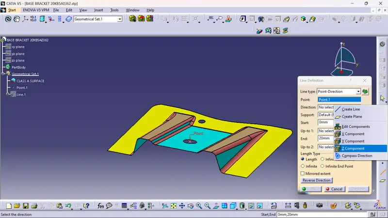
- TAKE A LINE DRAW LINE WITH THAT CIRCLE AND MAKE IT BOLD AND DOTTED..
- First ensure the class-A surface is properly joined and has no discontinuity on it. For this we can use boundary command or join command.
- Analyze the model manually or visually to see which direction is most suitable for tooling axis.
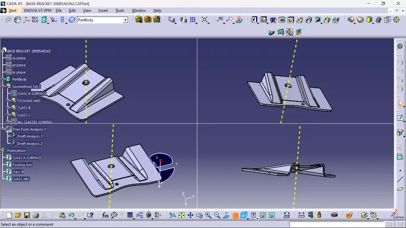
- As in 3D view we can see 2 holes and a flat surface, we can directly take the tooling axis perpendicular to that. But to be sure,let us analaze from all the views. The below images of the front side and top views shows the areas that we have to keep in mind while choosing tooling axis. As from X we cannot see one hole so we cannot take axis along this. In Y we cannot see any holes so here too we cannot take tooling axis. But in Z we can see 2 holes and flat surface so we can take tooling axis.
- Intersect the ZX plane of the axis system with the input and we can see that there is no surface that can create problem during tooling in this direction.
- Intersect ZY plane and we are unsure of these two surfaces, so we make a line and bisect them both and this will be our tooling axis which, not so surprisingly, is the same as our guessed tooling axis.
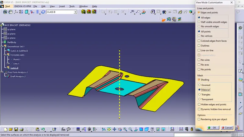
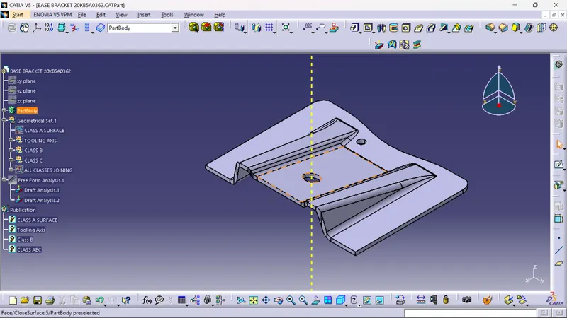
{"YELLOW DOTTED LINE IS TOOLING AXIS"}
Publication:
Publication is used to make easily accessible of the published components.
PERFORM THE DRAFT ANALYSIS-1:-
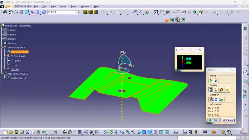
- Make sure the view mode of the part is in material shading.Then do to insert the menu and insert the featured draft analysis tool Pick the compass and align it with the tooling axis by dragging it.Then lock the draft direction and perform draft analysis by clicking on the component.
- The green color shows the positive daft tooling direction and the given surface passes the draft analysis.
- Click on the analyses under the running point to check the draft analysis on the individual faces. It shows how much draft on specific points when we move the cursor point.
Representation of Color variations in the draft analysis
GREEN COLOR - Positive Draft (3 degrees)
RED COLOR - 0-degree draft
BLUE COLOR - Negative Draft
Creating the Class-B surface
Procedures followed for creating the Class-B surfaces are
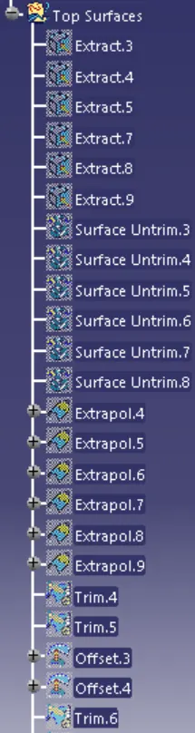
- Extract the ribs from the class-A surface one by one.
- Untrim the extracted surfaces
- Extrapolate the untrimmed surfaces with a required length
- Trim the extrapolated surfaces to achieve the desired rib shape
- Then offset the trimmed surface to 2.5mm downwards
Create a slant surface
- Extract the slant surface from the class-a surface
- Untrim the extracted surface
- Extrapolate the untrimmed surface
Create the base surface
The same procedure followed for the slant surface creation is implemented.
After creating all the required faces and surfaces perform the final trim and give the required fillets on the edges resulting in the final class-B surfacE
Creating the class-C surface
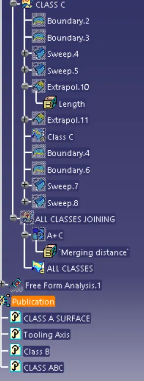
- Initially the first step is to create the boundary of the CLASS-A surface using the boundary command.
- By using the sweep command create the CLASS-C surface.
-
Then join the CLASS-A surface with the CLASS-C surface using the join commandFOR DRAFT ANALYSIS-2:
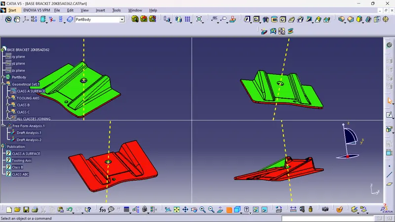
- Go to insert,analysis, feature draft analysis.
- Align the tooling axis with the compass.
- Click on the surface and see that the surface is within the permissible limit of the draft values.
- The surface should be green and in the column proper value (2.9deg) should be inserted.
- Changee the colurs red as blue and blue as red.
COMMANDS USED:-
This are the most used commands in this model of challange:-
- Extract
- Draft Analysis
- Trim - Surface untrim
- Extrapolate
- Offset
- Edge fillet
- Boundary
- Sweep
- Join
- Close (part design)
TREE STRUCTURE:-
CONCLUSION:-
From the given class A surface the Class B and C surfaces for the Base Bracket were created and by creating a tooling direction for manufacturing the Base Bracket was analyzed and found successful