Surface Modeling of Aston Martin Car Using SolidWorks
Title: Surface Modeling of Aston Martin Car using SolidWorks
Objective:
This project particularly aims to up skill and develop surface modeling techniques and its methods. It also aims in understanding solid modeling, assembly design and generating realistic rendering images.
Introduction:
It is best to make sure that your hardware and software are compatible with SolidWorks system requirements. SolidWorks can be installed natively on both 32- and 64-bit operating systems. Make sure your system have enough memory to run SolidWorks Visualize add-in for rendering.
SolidWorks is one of the most used computer aided design (CAD) and computer aided engineering (CAE) program across the globe. SolidWorks is one of the best solution capable of addressing the complete product development process, from product concept specification through product in service in a fully integrated and associated manner. As a result many industries use this platform for their product development and this platform allow users to develop 3D models in a simulated environment for both design and analysis. SolidWorks is published by Dassault Systems and founded by Massachusetts Institute of Technology.
SolidWorks model is made up of:
- Part – 2D design (sketch), 3D design (features), Part design consider in the part design section
- Assembly – Assembly design allows the design of assemblies with an intuitive and flexible user interface. Two or more components are assembled together at their respective work positions using parametric relations
- Drawing – Designing with standards is considered in the drawing section
Need of Surface Modeling:
Surface modeling is a method of creating planar or non-planar complex geometry which has zero thickness. Surfaces give much more flexibility when creating complex shapes that cannot be done using solid features such as car body panels, aircraft fuselages, fan blades or boat bodies. A complex surface can be very difficult to visualize without a physical model and surface modeling using computer eases this process considerably.
Design Methodology / Approach:
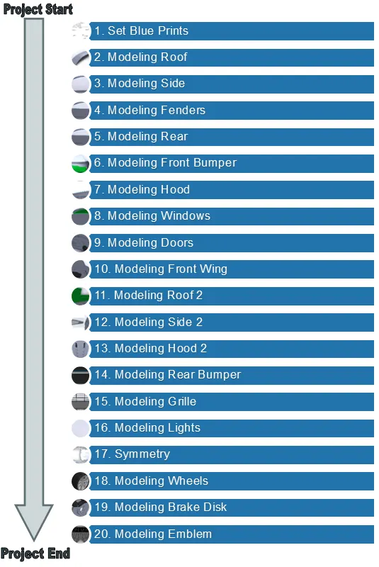
The design methodology section is very important because it gives a clear insight how to tackle the surface modeling of the car. It also provides a work plan and describes all the necessary activities for the completion of the project. The approach followed during the modeling are shown in the chart below.
Description:
Blueprint setup:
2D-Blueprints are the basic foundation to create 3D models. It helps in modeling step by step, which tools, techniques and methods to approach in developing a three dimensional models. First step would be to import all the required blueprints (front, rear, side, and top) into the SolidWorks workbench and proceed to draw curves and lines over a picture. This part will be the main file of the project and most of the modelization process will take place from here.
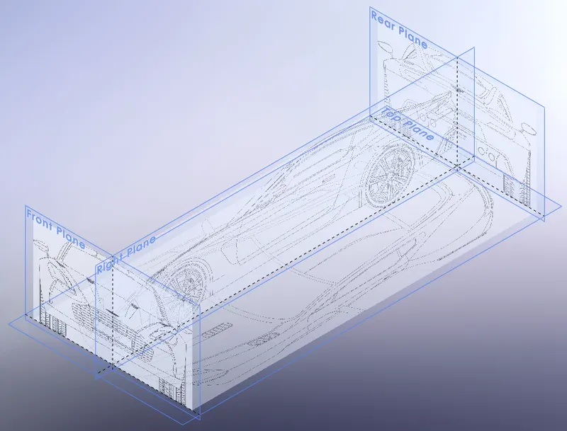
As blueprints are imported, the default unit system must be adopted according to our design requirements (CGS-Units). During this phase we encounter planes, dimensioning properties (height, width, and length), reference geometry, and transparency.
Roof modeling:
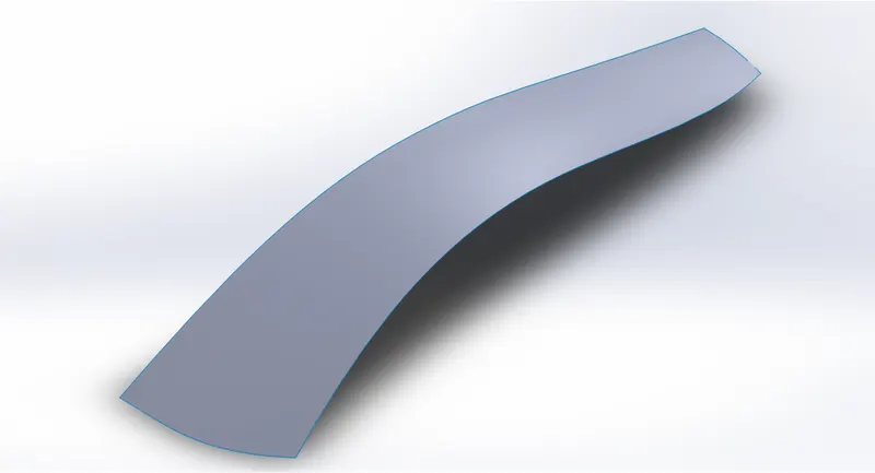
Roof is often taken as a straight point, as its construction is quite easy and uses curves spanning the entire model. Since the car is symmetrical, we build only half the roof model. This phase highlights some key concepts like sketches, projected curves, splines, smart dimension tool, line, and centerline and boundary surface. The curvature of the splines can be controlled by controlling the spline handles and arrows (steer and length). The boundary surface feature lets you create surfaces that can be tangent or curvature continuous in both directions namely Direction 1 and Direction 2 (all sides of the surface).
Side Modeling:
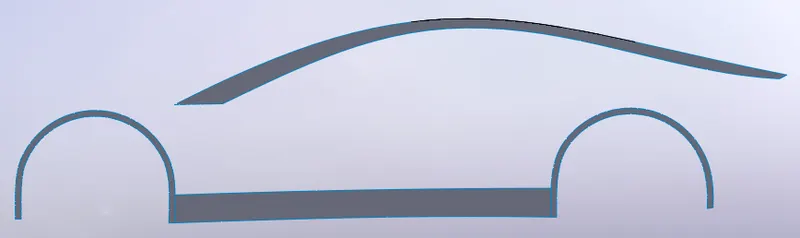
As early mentioned about splines, they play a very important role in developing the model and modeling car’s side also requires an extensive use of splines. During this phase, we are exposed to the concepts such as Trim and Offset Entities, Extruded and Trim surface.
- Extruded Surface: This feature extrudes the sketch profile into a surface
- Trim Surface: This tool trims the intersecting surfaces. Standard and mutual are 2 types of trim and under selections one chooses a sketch and an extruded surface for trim
Fenders modeling:
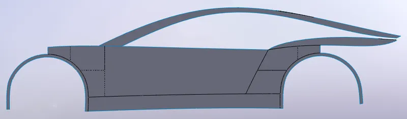
Creating fenders requires extra planes and with these planes extra profiles are created and linked to the lower surface of the side. In this stage a new command is introduced, i.e. Surface fill and it is used to patch a surface with any number of sides, within a boundary defined by existing model edges, sketches, or curves, including composite curves. 3D-sketch and Knit- Surface are the other two commands introduced during the fenders modeling.
- 3D-Sketch: With this feature we can create 3D sketch entities on a working plane, or at any arbitrary point in 3D space
- Knit-Surface: With this option two or more faces and surfaces can be combined into one
Rear modeling:
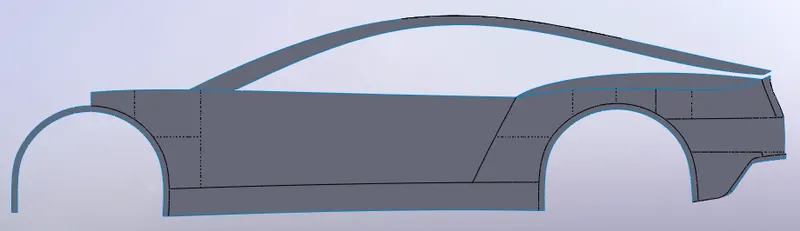
Till we saw some basic commands regarding the surface design. Below figure makes clear that the side and fenders surface connects the rear smooth curved surface. In order to create such a smooth curved surface some new commands have to be used, i.e. Surface-Offset, Delete-Face, Ruled Surface, and Fillet.
- Surface-Offset: This feature creates a surface from the existing surface and we can also create an offset surface with a distance of zero
- Delete-Face: This feature deletes a face from a surface body, or deletes one or more faces from a solid body to create surfaces
- Ruled-Surface: This creates surfaces that extend out in a specified direction from selected edges. Tangent to surface, Normal to surface and Sweep are the types ruled surfaces used in this project
- Fillet: This option helps to smooth the edge between two adjacent faces
Front Bumper Modeling:
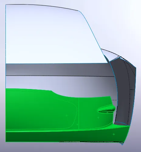
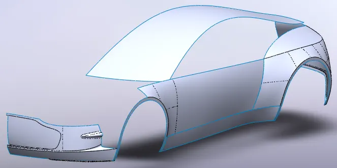
Front bumper is as complex as rear curved surface. To complete such a front bumper following commands such as Boss/Base thicken, Split, and Body-Move/Copy.
- Thicken: It creates a solid feature by thickening one or more adjacent surfaces
- Split: Split feature is used to split surface from the existing sketch. With this option we can divide the selected faces
Hood Modeling:
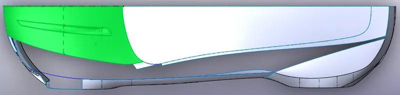
To model the hood surface correctly, we need the profiles shared with the roof as a reference. By using regular commands we can create the hood surface, i.e. the boundary surface, trim-surface and surface-fill features. Hood surface as two slight hollows and these can be created by trimming the hood surface and using surface-fill option.
Windows modeling:
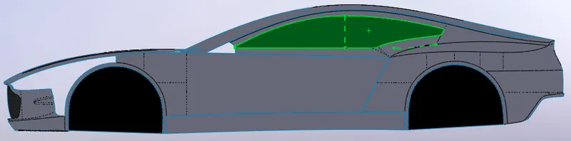
This chapter aims at modeling the window, which is part between roof and door. Before proceeding with this part, we need to finish the rear of the car. Fillet/Round with variable size fillet feature, i.e. variable radius parameters tool is used to overcome the sharp edges. Along with this part, the surfaces behind the wheels, that partially hidden from outside of the car when the wheel is present are also created.
Door Modeling:
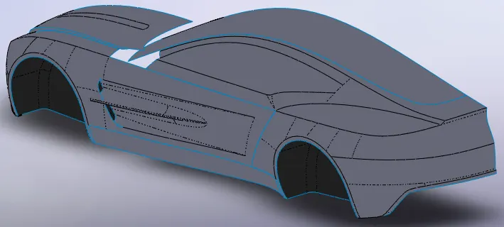
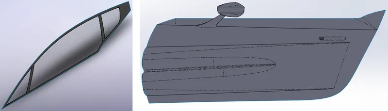
Here we focus on creating the door and most interesting part of this door is the shape of the hole as seen in the below figure. An oval shape extruded surface is created to see the end effect of the hole shape on the door. In doing so we encounter mirror command.
- Pattern/Mirror: This tool creates a copy of one or more features, mirrored about a face or a plane. Sketch, faces, solid parts can be mirrored with this option
Front wing modeling:
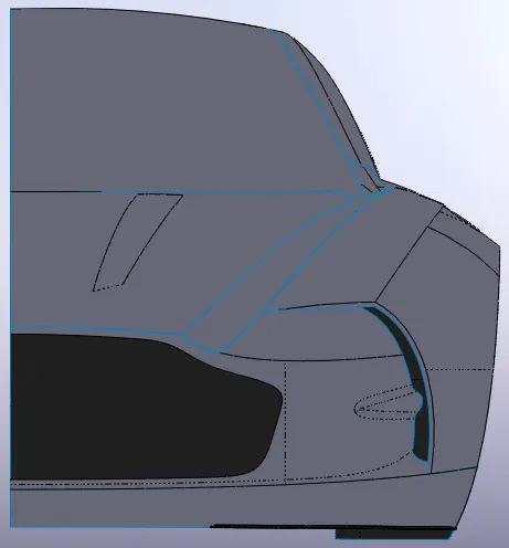
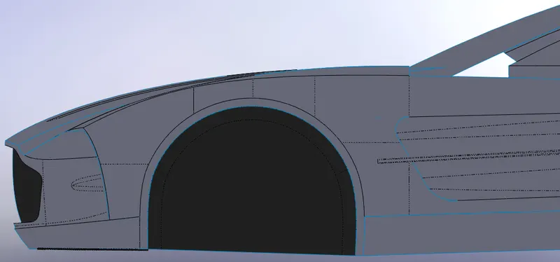
Front wing is one of the fancy geometry of the Aston Martin and it is created by using the known commands. Here we encounter a new commands, i.e. the Surface-Loft and Body-Move/Copy.
- Surface-Loft: Loft creates a feature by making transitions between profiles, i.e. in this case two edges. A loft can be a base, boss, cut, or surface and can be created using two or more profiles. Only the first, last, or first and last profiles can be points. All sketch entities, including guide curves and profiles, can be contained in a single 3D sketch
- Body-Move/Copy: With this feature one can you can move, rotate, and copy solid and surface bodies, or place them using mates
Roof 2 modeling:
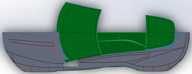
Windshield and rear window are created from the roof and further details are added by separating them from the roof surface and later assembled in special file. Windshield and rear window are exported by right-clicking on the surface body and clicking on insert into new part. Now the separated parts have a default unit system, which has to be updated according to our project requirement (CGS). Here we encounter new command like Split-Line.
- Split-Line: This feature projects an entity to surfaces, or curved or planar faces. It divides a selected face into multiple separated faces
Side 2 modeling:
Aston martin window and door are created in this chapter and this is carried by the concept of splitting the car into several SolidWorks files and later brought together in the assembly. Here a command Surface-Offset, Cut-Extrude, and Boss/Base-Extruded.
- Surface-Offset: This command gives the option to see and remove any surfaces that cannot be offset, building the remaining geometry
- Cut-Extrude: This feature is used to extend a sketched profile in one or two directions as either a thin feature or a solid feature. Cut-Extrude means removes a material form a part
- Boss/Base-Extrude: Is same as cut-extrude, but it adds the material to the part
Hood 2 modeling:
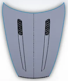
Until now we used different commands to build some simple to complex surface geometries and this chapter gives an insight about solid modeling. Surface-Cut, Linear-Pattern and Combine features are used to design the hood.
- Surface-Cut: This feature can cut a solid model by removing a material with surface or a plane. With multibody parts, you can select which bodies to keep
- Linear-Pattern: This tool creates multiple instances of one or more features that can be uniformly spaced along one or two linear paths
- Combine: Two or more solid bodies can be combined to create single-bodied part or multibody part. Add, subtract, and commonare the options
Rear-Bumper modeling:
This chapter also includes a combination of both surface and solid modeling. Here a new command Shell is introduced. Tail light, rear spoiler, bumper fins, silencer and reflectors are created in this chapter to form a rear-bumper.
- Shell: It is used to define the thickness of thin and thick shell elements

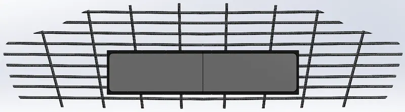
Grille modeling:
Lights modeling:
Headlights are hard to design due to their complicated geometry and lack of visibility.
Here a Curve-Driven-Pattern command is used and it allows to create patterns along a planar or 3D curve. Sketch, edge, open or closed curve can be used as a pattern.

Symmetry:
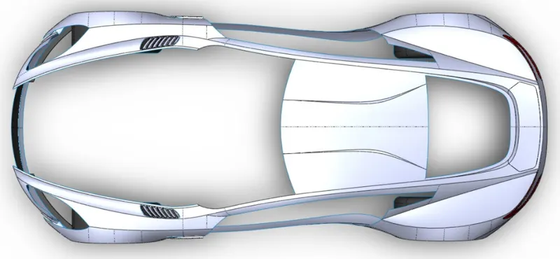
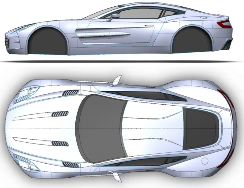
So far we worked only on one side of the plane, i.e. half the main body. Now using mirror option we can mirror the car’s main body into a single part. For every pair of surface bodies across side plane we need to knit the surfaces together to make it a single entity. Along with this fuel tank door is also designed as shown in figure.
Wheels – Brake Disk – Emblem modeling:
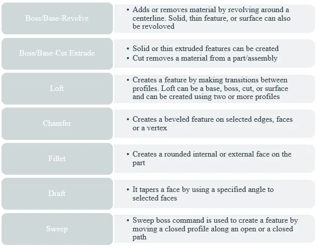
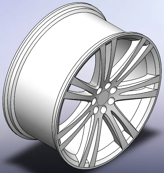
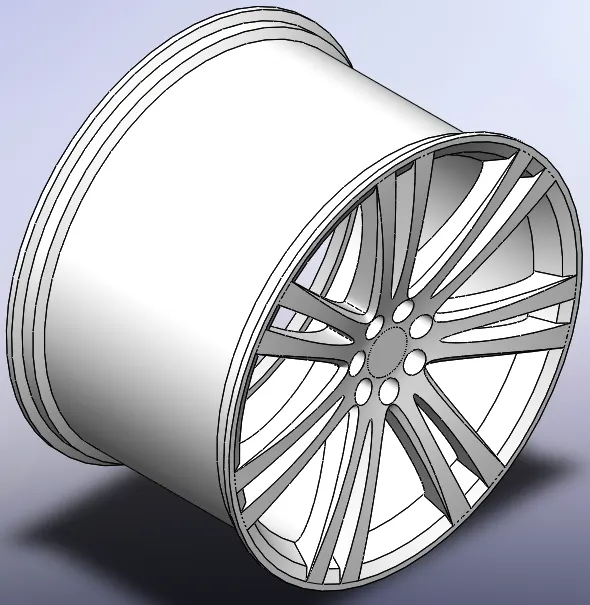
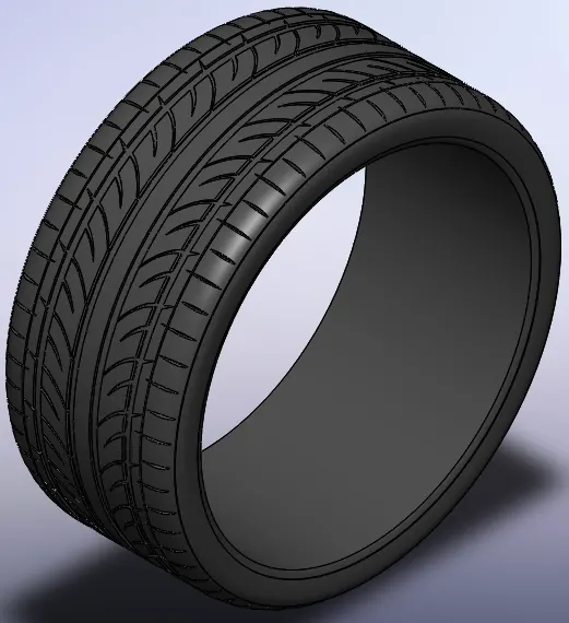
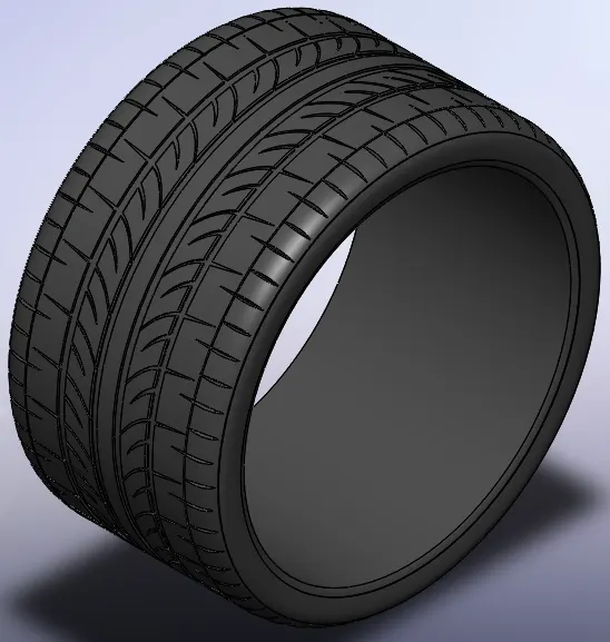
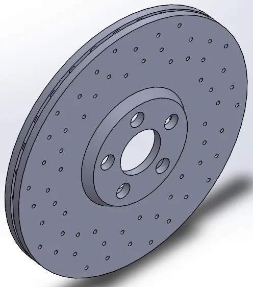
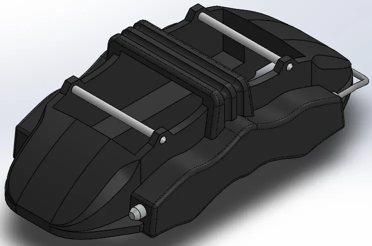
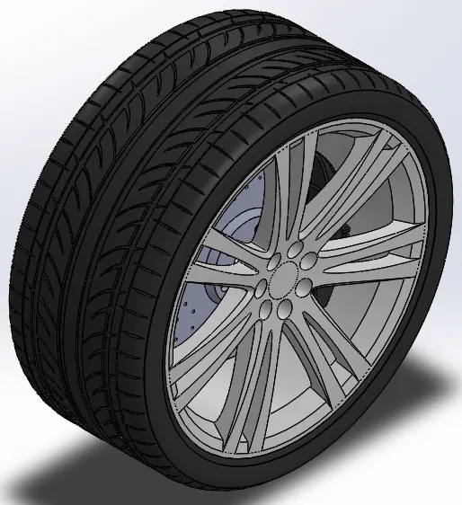
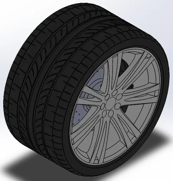
Up to now, we have seen surface modeling, its techniques and methods to create car’s main body and other components. Now we need to use complete solid modeling techniques to design brake disc, caliper, rim, wheels and emblem. Finally, we bring all the components together in assembly design workbench.
Features that are used for solid modeling are mentioned as follows.
Front Rim Rear Rim
Front Tire Rear Tire
Brake Disc Caliper
Emblem
Assembly Design:
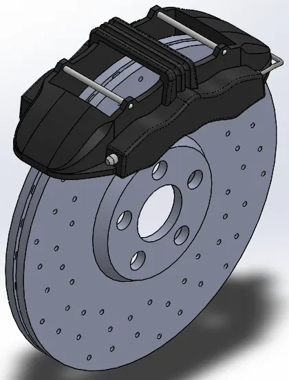
The second component is the assembly. Assemblies are collections of parts which are assembled in a particular fashion using mates (constraints). Any complex model will usually consist one, or more assemblies. When SOLIDWORKS opens the assembly, it finds the component file to show it in the assembly. Changes in the component are automatically reflected in the assembly.
Assembly Feature Manager:
- Top-level assembly, Assembly planes and origin
- Various folders, for example, Annotations and Mates
- Components (subassemblies and individual parts), and Grouped components
- Assembly features (cuts or holes), and component patterns
Brake Disc Assembly
Fron Wheel Assembly Rear Wheel Assembly
Isomteric View
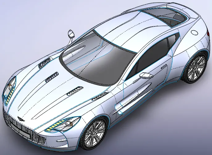
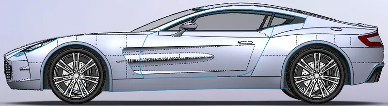
Side View
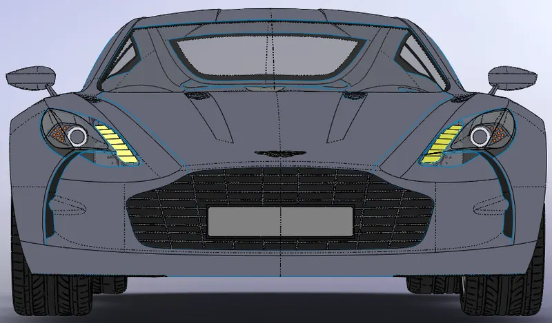
Front View
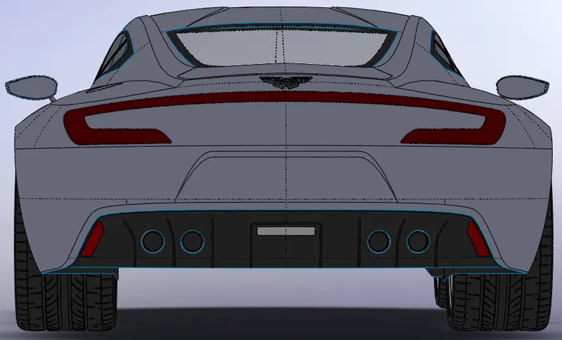
Rear View
Rendering:
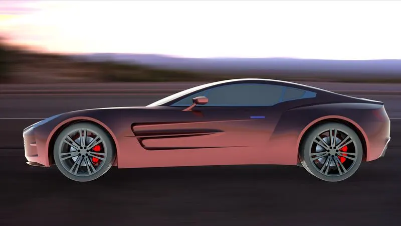
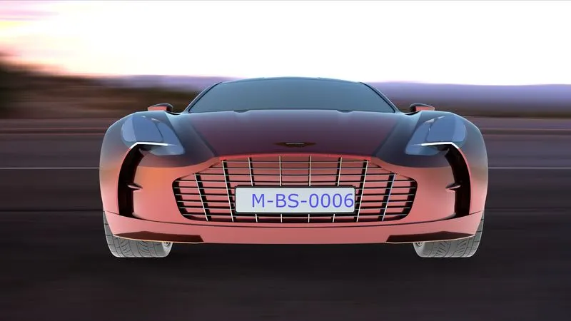
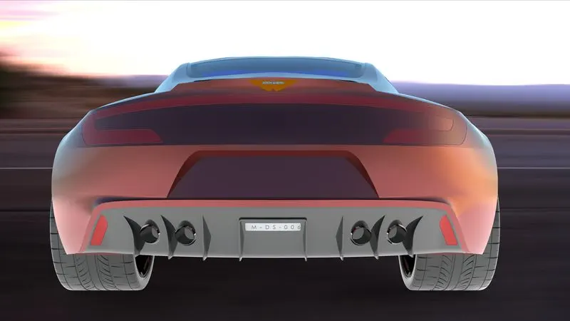
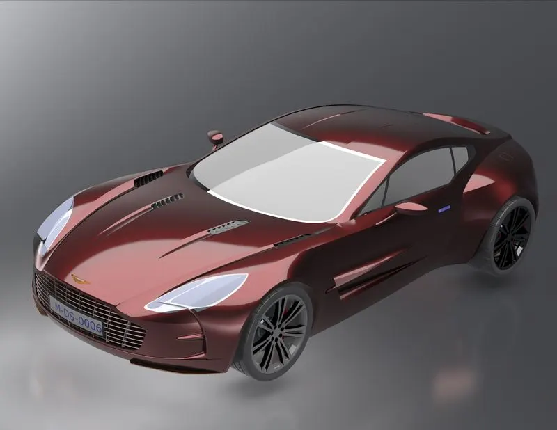
SolidWorks-Visualize product provide a suite of standalone software tool that combine industry-leading rendering capabilities with design-oriented features and this is where you get the photorealism image. The rendered image improves the appearances, lightning, quality, and scene of the created design.
Conclusion:
The project “Aston Martin-One77” highlights the importance of surface modeling techniques and also gives an insight about combining surface and solid models in assembly design workbench for creating complex shapes. Alongside we learnt how to fine-tune small details of SolidWorks model by controlling its topology, and manipulating one or more faces in order to achieve the desired result.