Aston Martin ONE-77 Challenge-11 (Project)
Surface modelling, assembly and rendering of Aston martin one-77 car
Objective-
- To surface modelling, parts modelling and parts assembling of Aston martin one-77 car with fully define sketches and appropriate appearances.
- To render the car model by adding appearances, decals, lights, camera and background scenes.
Software used
- Solid work 2019
- Solid work visualize 2019
Introduction
- Solid work- Solid work is a software which is developed by dassault systemes and used for CAD (computer-aided design) and CAE (computer-aided engineering).
- Aston martin- Aston martin is a British public limited company, founded in 1913 and known for manufacturing luxury sport cars and grand tourers.
- Aston martin one- 77 car- It is a cars model manufactured by Aston Martin Company and designed by Marek Reichmann.
Some interesting facts about this car is, this model manufactured in 2009-2012 and only 77 model’s are available in the world, that’s why this model name is one-77.
Design approach flowchart-
Command used
Sketch command
- 2D sketch- 2D sketch is a command for making sketches to required solid bodies. We have to choose any one plane for start sketch with front, top or right plane
- 3Dsketch- 3D sketch is a command for making sketches without any plane required. The sketch will be 3 dimensional rather than 2 dimensional.
- Line- For making line this command used. And have two another types of line constructing line and mid-point line.
- Circle- For making circle this command use. And have another types which is perimeter circle which need three points to make circle.
- Spline- It is used for making desired curve basically a cure which is very complex to make. Therefore this command comes very helpful and also have 3 another types- style spline, spline on surface, and equation driven curve.
- Rectangle- Rectangle tool is used for making rectangle and this tool have four types- centre rectangle, 3 point corner rectangle, 3 point centre rectangle, and parallelogram.
- Convert entities- Converts selected model edges or sketch entities into sketch segment.
- Offset entities- Add sketch entities by offsetting face edges, curve, or sketch entities a specified distance.
- Trim entities- Trim or extends a sketch entity to be coincident to another or deletes a sketch entities.
- Mirror entities- Mirror selected entities about a centreline or place reference.
- Circular sketch pattern- Add a circular pattern of sketch entities.
- Move entities- Move a sketch one place to another place.
- Smart dimension- Create a dimension for one or more selected entities.
- Sketch picture- To insert the sketch picture as a blue print setup.
- Display/delete relations- Display and delete geometrical relation.
Features command
- Fillet- Creates a rounded internal or external face along one or more edges in solid or surface feature.
- Chamfer- Creates a bevel feature along an edge, a chain of tangent edges, or a vertex.
- Draft- Tapers model faces by a specified angle, using a neutral plane or a parting line.
- Dome- To give tapper foe solid bodies
- Combine- Dombine two or more bodies.
- Split- Creates multiple bodies for a single body. You can create the bodies in the existing part or in separate parts.
- Move/copy body- Moves, copies and rotates solid and surface bodies.
- Delete/keep body- Deletes or keeps one or more solid or surface bodies.
Boss/base command
- Boss extrude- Extrudes a sketch or selected sketch contours in one or two directions to create a solid bodies.
- Boss revolve- Revolves a sketch or selected sketch contour around an axis to create a solid feature.
- Sweep- Sweeps a closed profile along an open or closed path to create a solid bodies.
- Loft- Adds material between two or more profiles to create a solid feature.
Cut command
- Cut extrude- Cuts a solid model by extruding a sketch profile in one or two direction.
- Revolve cut- Cuts a solid model by revolving a sketched profile around an axis.
- Cut with surface- Cuts a solid model by remaining material with surface.
Surface command
- Surface extrude- Creates an extruded surface with sketch.
- Surface loft- Creates a lofted surface between two or more profile.
- Boundary surface- Creates a boundary surface between profiles in two direction.
- Fillet/round- Creates a rounded internal or external face along one or more edges in solid or surface feature.
- Chamfer- Creates a bevel feature along an edge, chain of tangent edges, or a vertex.
- Fill surface- Creates a surface patch within a boundary defined by existing model edge, sketches or curves.
- Surface offset- Creates offset surfaces using one or more contiguous faces.
- Ruled surface- Inserts ruled surfaces from edges.
- Surface extend- Extend the edges, multiple edges or the face on a surface based on end condition and extension type.
- Surface trim- Trims a surface where one surface intersects with another surface, a plane or a sketch.
- Knit surface- Combines two or more adjacent, non-intersection surfaces together.
- Delete face- Deletes faces form solid bodies to creates, or deletes faces from a surface bodies.
Curve command
- Projected curve- Creates a 3D sketch using two 2D sketches.
- Split line- Creates curves on the solid bodies using sketches.
Key concept for design
- Curve generation in solid work
- Splines
- Splines vector
- Equal curvature for spline
- Constraining the spline
- Projected curve creation
- Composite curve creation
- Surface generation using curves and sketches
- Boundary surfaces
- Lofted surfaces
- Ruled surfaces
- Reference plane
- Surface trim
- Surface knit
- Move/copy surfaces
- Mirror surfaces
- Application of solid modelling
- Revolve boss
- Extrude cut
- Linear and circular pattern
- Fillets
- Chamfers
- Split bodies
- Creation of wheels
- Assembly module
- Inserting the parts
- Mates in assembly
- Sub assembly creations
- float & fix parts assembly
- Importing sub-assemblies to another assemblies
Methodology
- Surface modelling
- Blue print setup(BP setup)- Blue prints are the reproduction of the original drawing which was firstly made by an architect or a draughts man or a designer, and blue prints are used to make multiple copies or zerox of that kind of object.
Here I used blueprints to give my Aston martin car a perfection model as a design.
Feature used for setup
- Sketch picture
Methodology used-
- Firstly Inserts the blue prints
- Then Sets the dimensions of BP in centimetres
- Then Untick enable scale tool & lock aspect ratio
- After that Seted the transparency
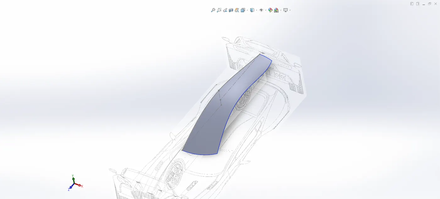
- Modelling of roof, sides, back rails- These all are the surfaces of the car and together these makes car’s body, where roof are used to weather protection and sometime used for luggage career and sides of the car are used to provide gates in the car whereas back rails are the back side of the car which depends on the car design some time it used to make extra extra space to carry luggage.
Feature used
- Sketch tools
- Boundary surface
- Fill surface
- Offset surface
- Ruled surface
- Knit surface
- Trim surface
- Cut with surface
- Smart dimension
- Fillet
- Projected curve
- Etc.
Methodology used-
- Started one side sketches with the help of side and top BP and make fully defined with proper dimensions and relations for neglecting errors in surface generation
- Generated curves with the help of fully defined sketches
- After that with the help of curves generate needed surfaces
- Trims the extra surfaces where needed to be trim
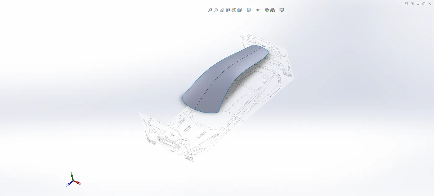
Roof
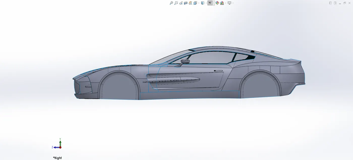
Side
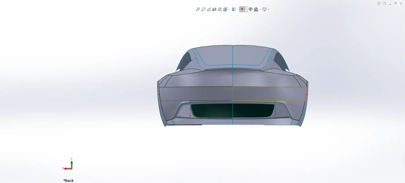
Back rails
- Parts modelling
- Modelling of windshield, windows, rear lights, front light- These are the fixed parts of the car where wind shields protect with air coming when car in speed and window are used for internal environment of the car for comfort whereas rear light and front lights are mainly used to travel in night for escaping with accidents.
Feature used
- Insert into new part
- Sketch tools
- Boundary surface
- Fillet
- Combine
- Delete/keep body
- Split
- Linear pattern
- Cut with surface
- Extend surface
- Trim surface
- Thicken
- Projected
- Split line
- Smart dimension
- Etc.
Methodology used-
- After creation of roofs, sides and back rails surface the windshield, window, rear lights and front light parts are creates in different file with insert into new parts command, these are the type of fixed parts
- After that with the help of BP’s and proper dimensions starts sketches
- And with sketches generated curves
- And with the help of curves generated surfaces
- And trims the extra surfaces where needed to be trim
- In the front lights the thin feature command used to give extra thin profile
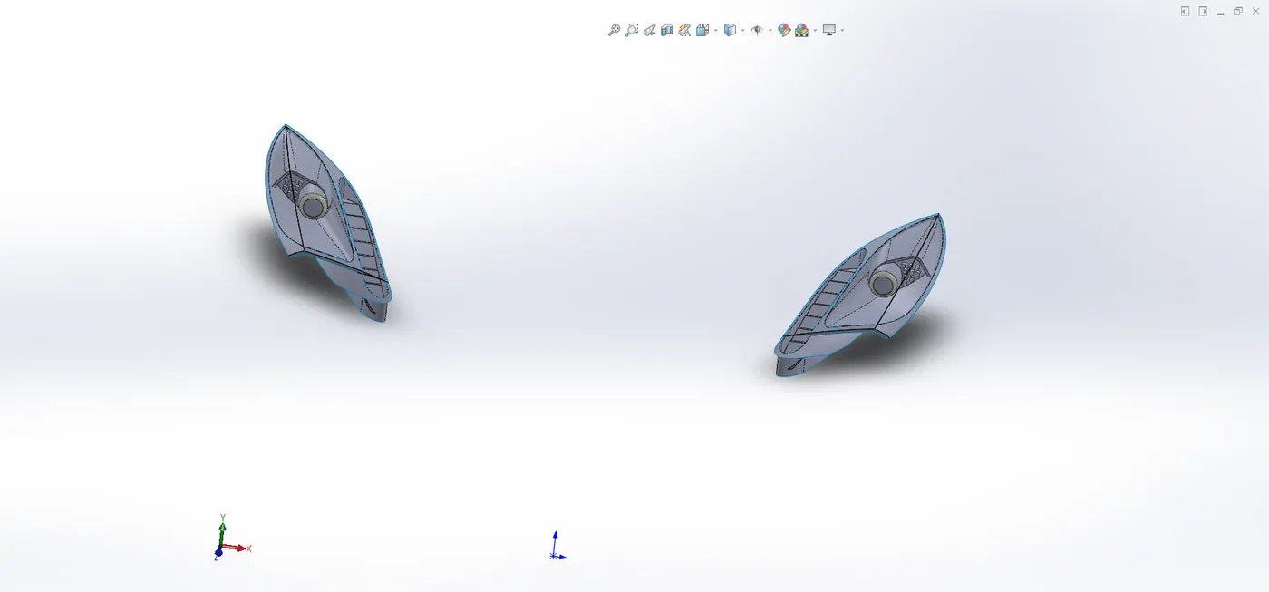
Front lights
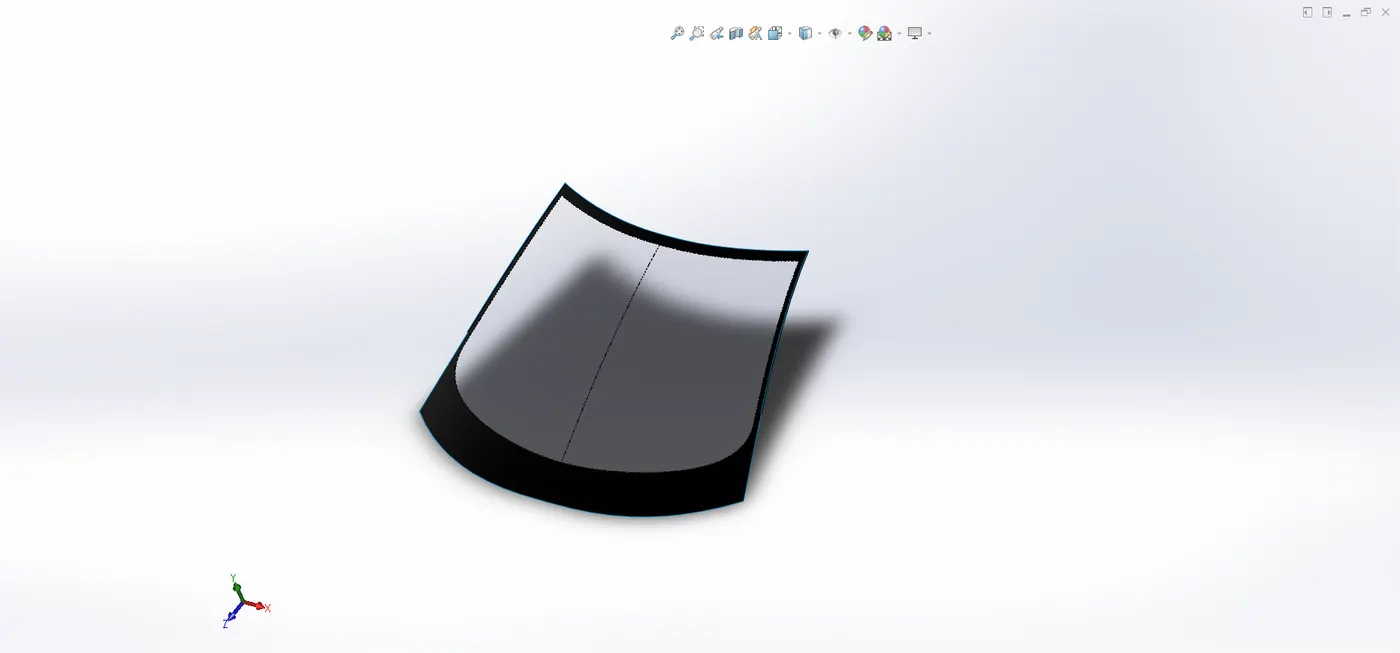
Windshield
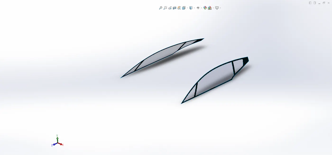
Windows
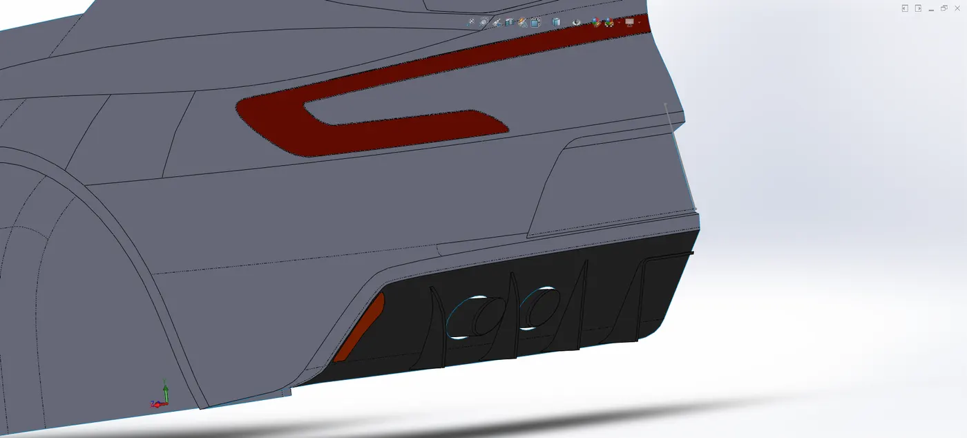
Rear lights
- Modelling of rims, wheels, disc brake, clipper- These parts are floating parts of the car and these parts make complete wheel to run on the road where rims are used to support the cars load and wheels runs on the road with direct contact with road whereas disc brake and clippers are used to stop the car without any jerk with accurate timing.
Feature used
- Boss extrude
- Revolved boss
- Sweep boss
- Lofted boss
- Cut extrude
- Draft
- Mirror
- Sketch tool
- Circular pattern
- Combine
- Fillet
- Delete/keep body
- Etc.
Methodology used-
- For these parts of the car started a new sketches and insert blue prints of wheel
- After that with the help of BP started sketch with proper dimensions and relations to make fully define the sketches
- And with the help of sketches created the solid profile of rims, wheels, disk brake and clipper
- Disk brake are created with ideal dimensions not with the help of BP
- The front wheel and rear wheel dimensions are different that’s why front and rear wheels are made separately
- Appearance are used to give for material and actual looks
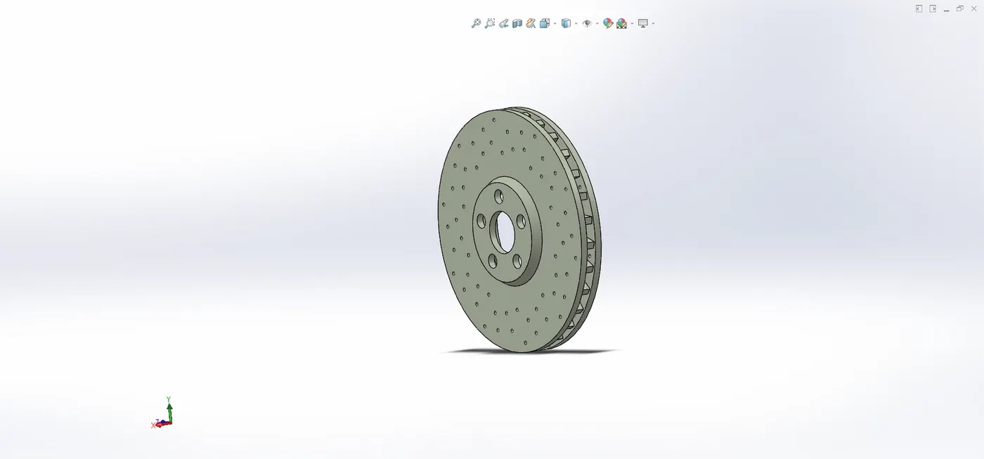
Brake disc
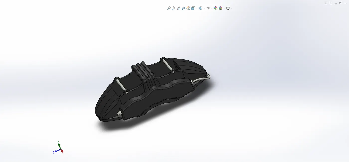
Clipper
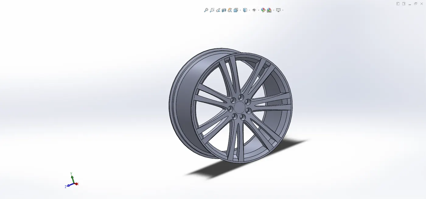
Rim
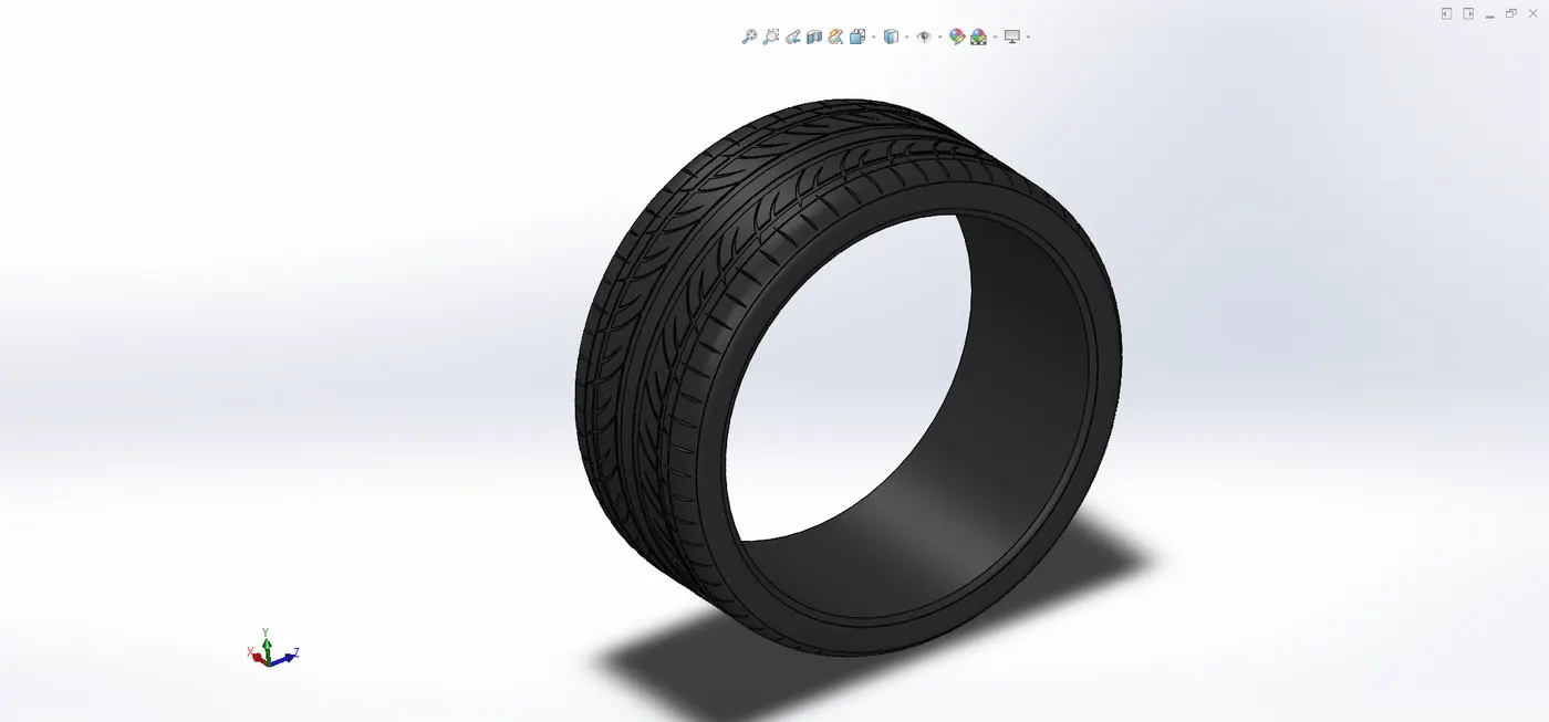
Tyre
- Emblem creation- Emblem is a visible object or representation symbolizes or a concept like a moral truth or a person or an allegory.
Here the emblem represents the Aston martin company.
Feature used
- blue prints
- sketch tools
- boss extrude
- cut extrude
- combine
- smart dimension
- delete/keep body
- Etc.
Methodology used-
- For making emblem started a new sketch and insert blue prints of emblem
- With the help of BP started sketches an make them fully defined with dimensions and relations
- After that created a solid profile of emblem
- And used appearance for proper look of emblem
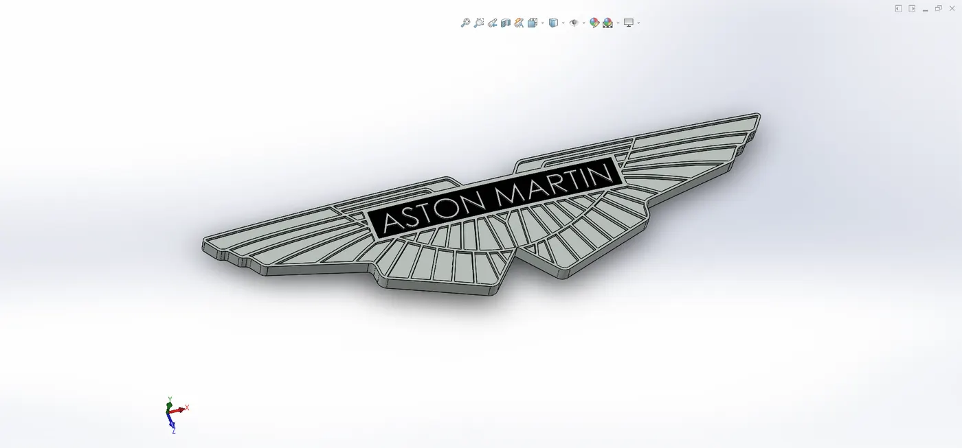
Aston martin emblem
- Creation of wheel assembly- The wheel assembly is that’s parts which complete the wheels and these parts are rim, clippers, brake disc, wheel tyre etc.
Feature used
- Mates
- Browse parts
- Etc.
Methodology used-
- Starts a new assembly and then inserts the all parts to make complete wheel, and that are rims, wheel, disc brake, clipper
- Make mates relation with all parts one by one
- Firstly brake disk and clipper then wheel and rim
- Then mates relation between assembly of clipper and assembly of rim to make complete wheels of front wheel and rear wheel
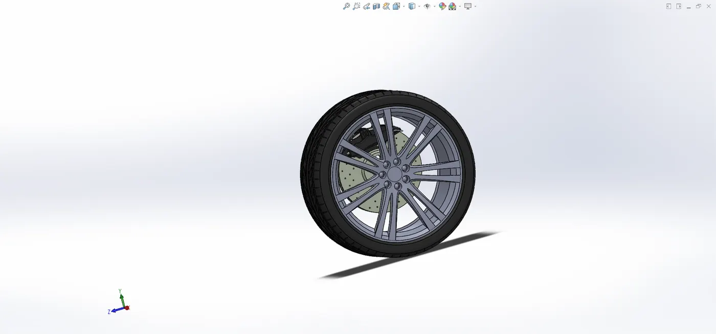
Assembled wheel
- Modelling of back reflector- Back reflector are for comfort driving to see the back said environment of the care to make sure for driver to change their direction according to needs.
Feature used
- Sketch tools
- Projected curve
- Thicken
- Knit
- Fillet
- Boundary surface
- Filled surface
- Etc.
Methodology used-
- After completing the sides, roof and back rail start sketch to modelling of back reflector
- With the help of blue prints of car completed fully defined sketch with the help of front, side and top BP one by one
- The generated curves with sketches and the surface modelling started
- The back reflector firstly made with some certain distance and then after connected with the side of the car
- Thin feature used for making mirror of the back reflector and sometime trim and, cut with surface command used
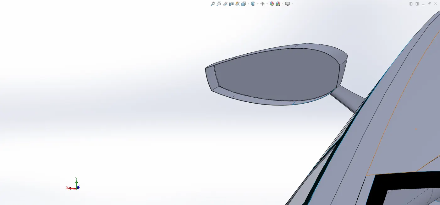
Back reflector
- Parts assembling
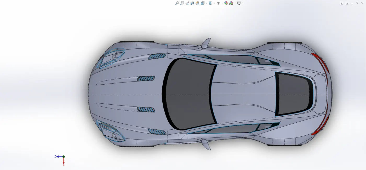
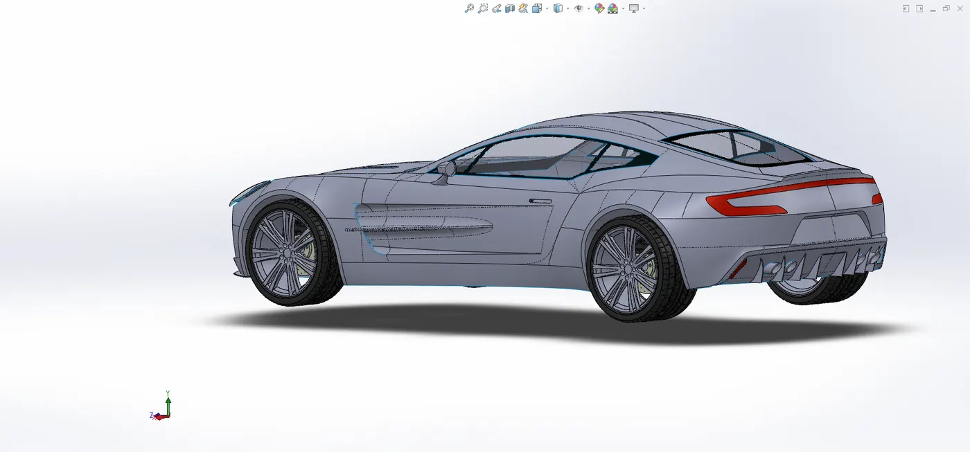
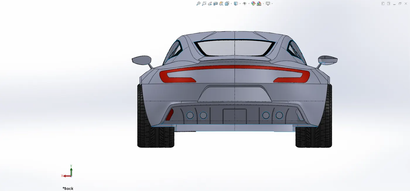
- Creating constrains with surface modelling & parts modelling- After making all floating and fixed parts and car surfaces now it’s time to final assembly of all parts with car to look like a final luxury Aston martin one-77 car.
Methodology used
- Firstly started new assembly and then inserts all parts one by one
- After that one by one give mates relations to their areas
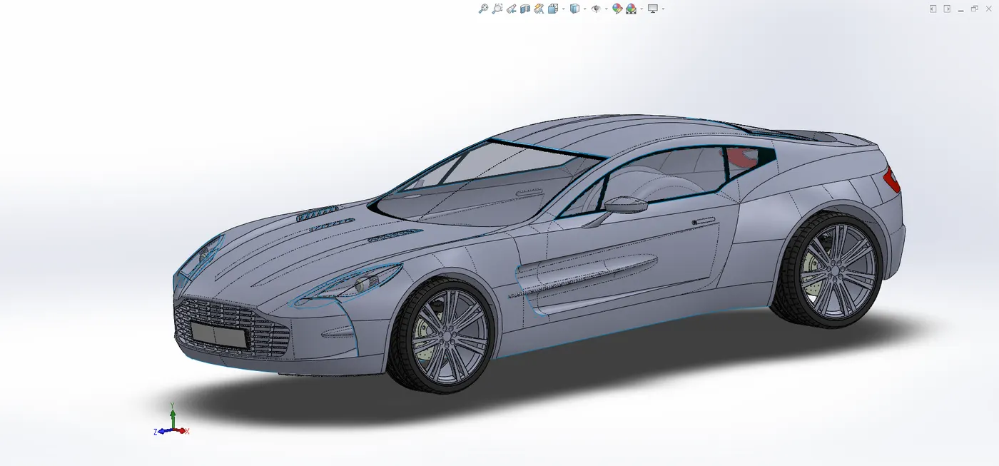
- Rendering
After using
- Appearance
- Lights
- Camera
- Backgrounds
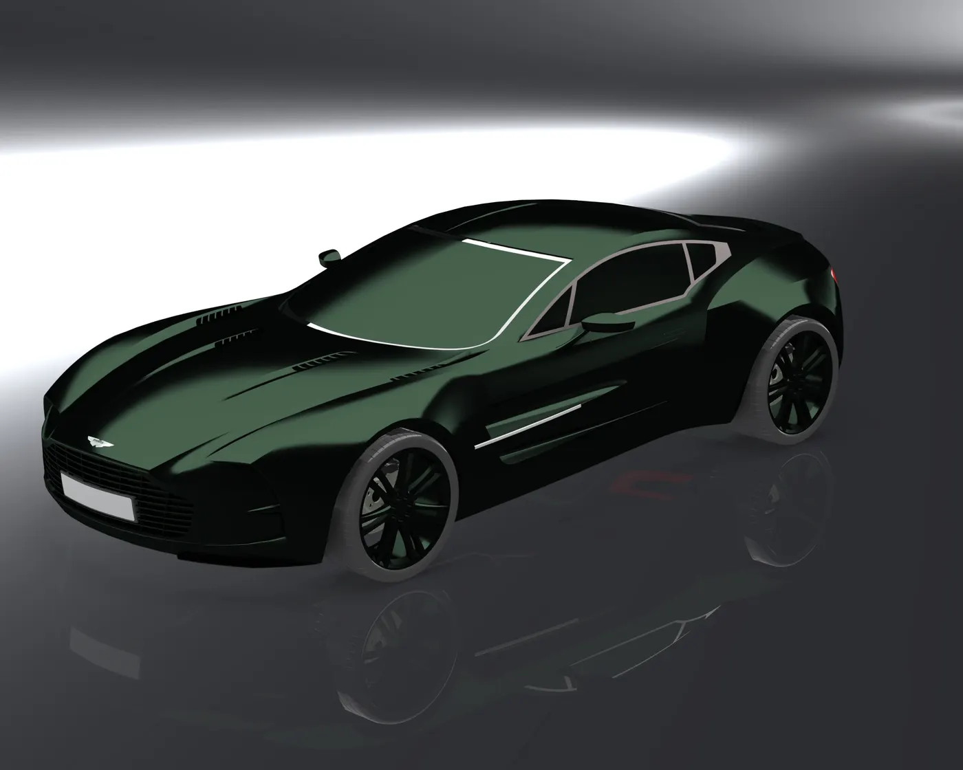
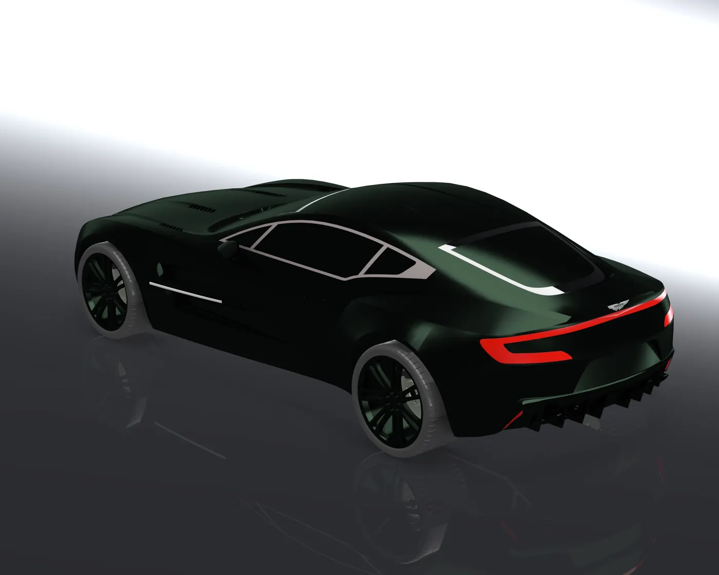
Conclusion- Thus the Aston martin one-77 car designed with using solid work 2019 and rendering with solid work visualise 2019.