CI Engine Modelling Techniques - IC-Engine Calibration Using GT-Power and GT-Suite.
IC-Engine Calibration Using GT-Power and GT-Suite
Assingment:4 ( CI Engine Modelling Techniques )
CI Engine Modelling :
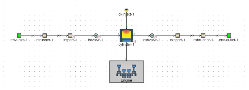
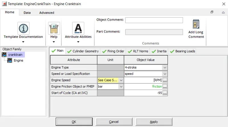
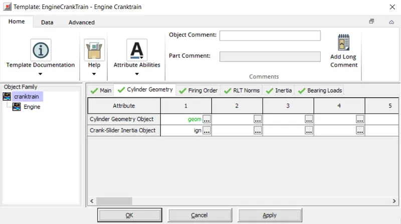
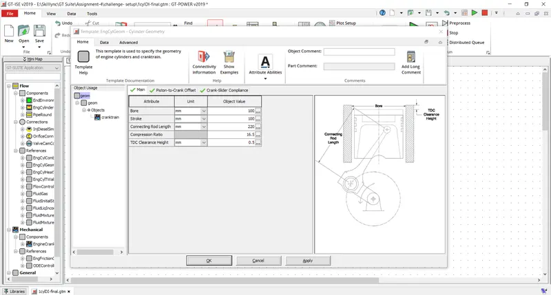
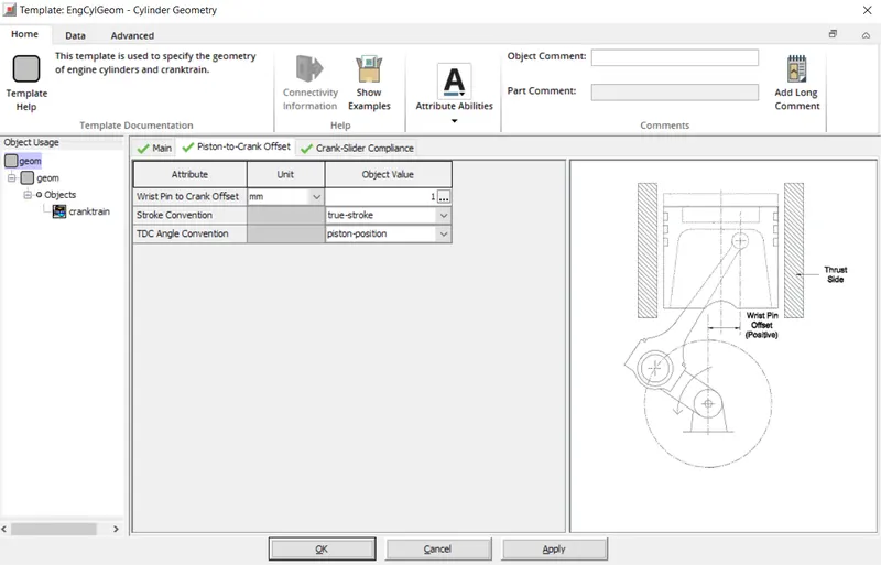
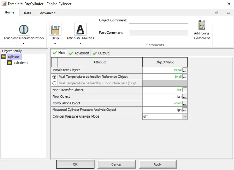
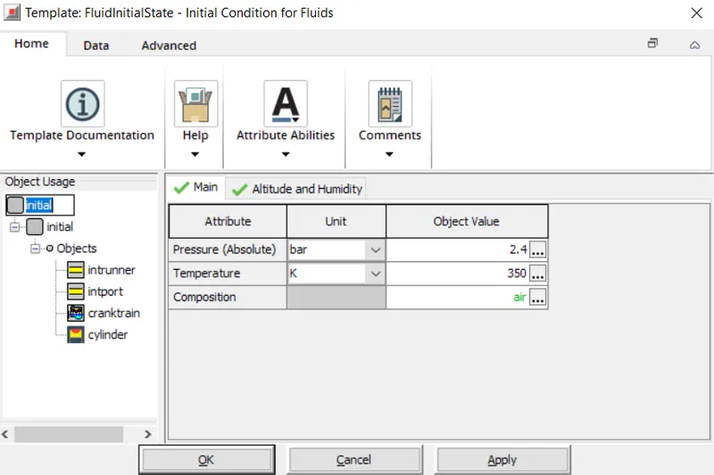
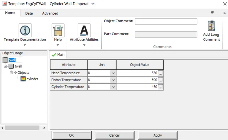
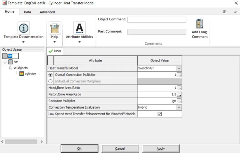
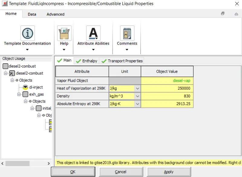
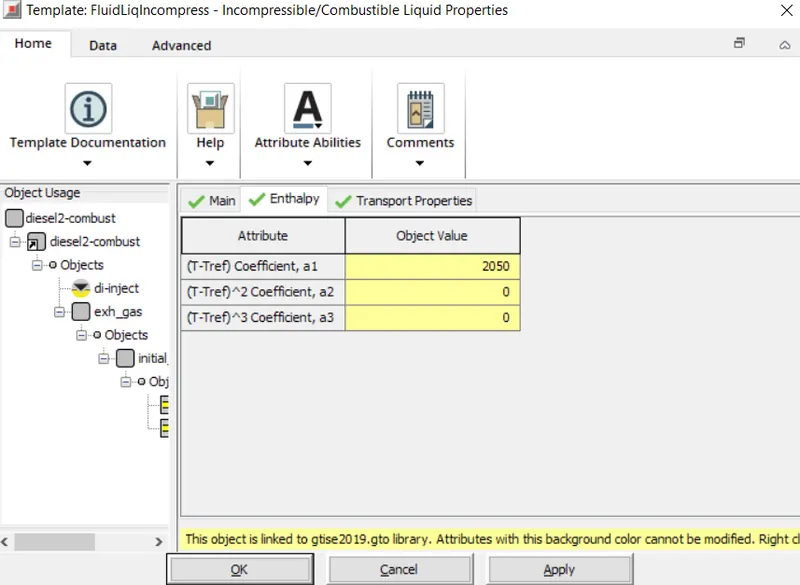
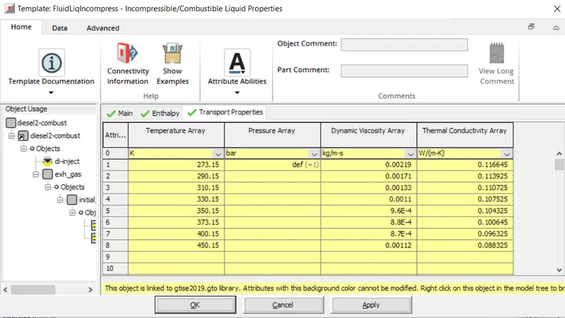
Injector
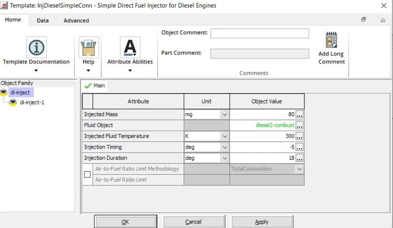
Intake Valve
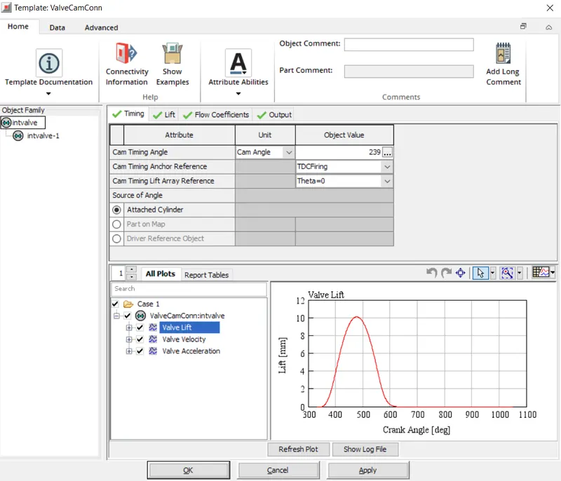
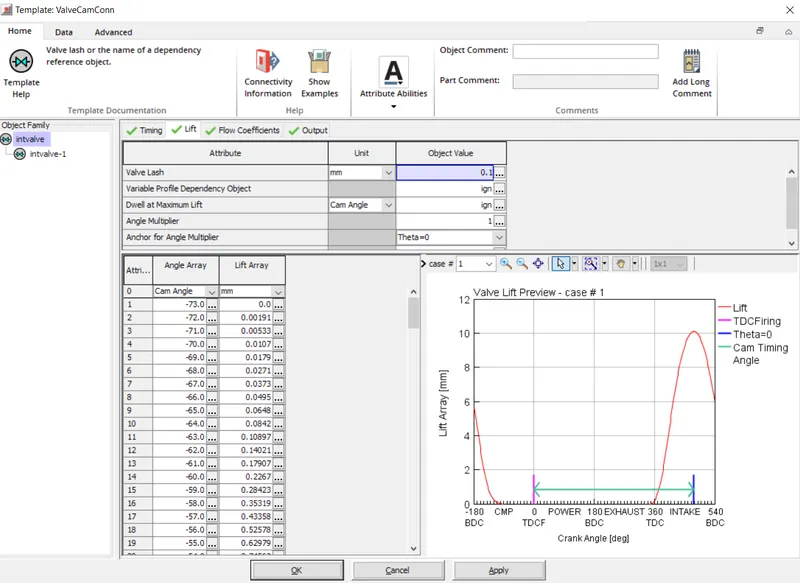
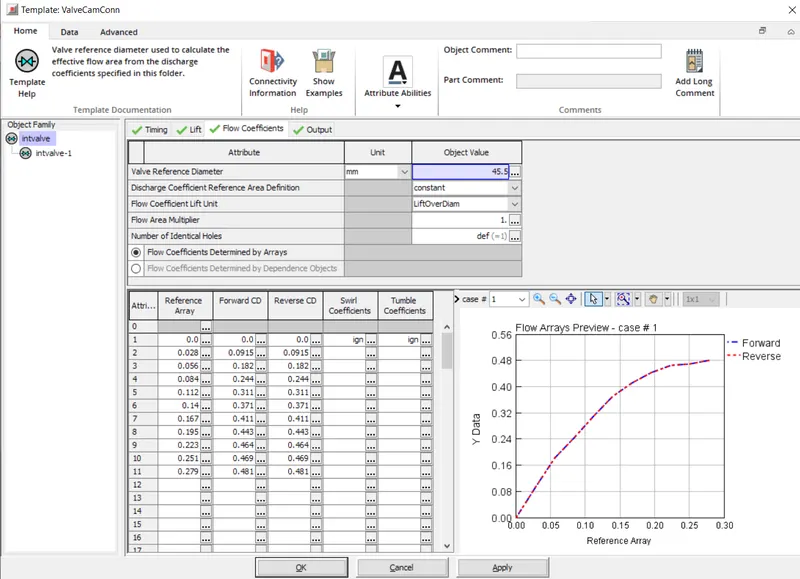
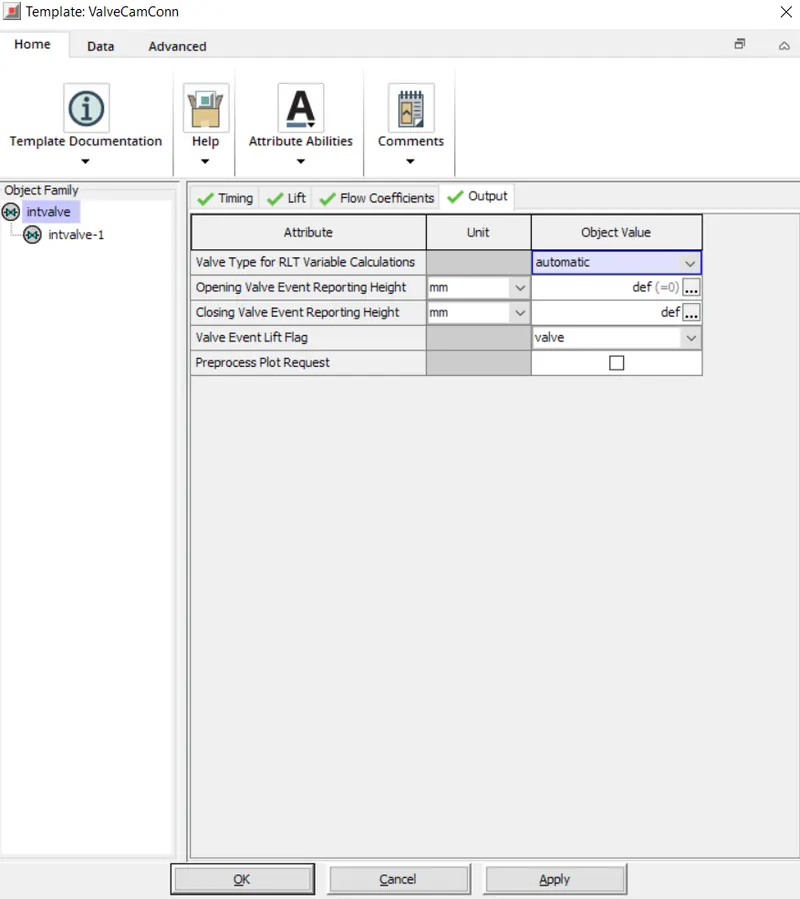
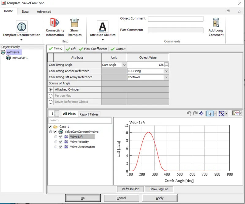
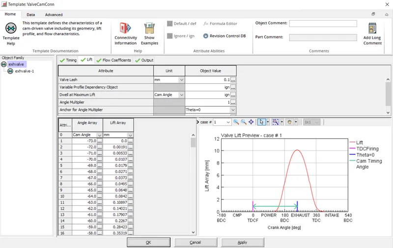
Exhaust Valve
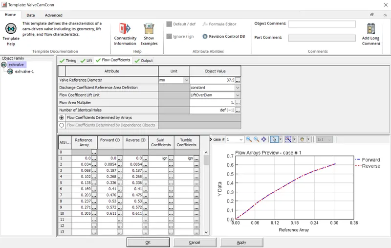
Results:
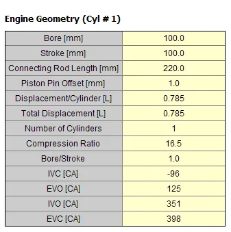
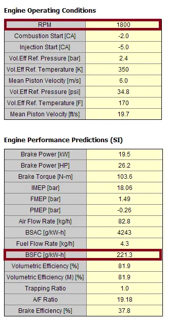
Q. Comparing SI-Engine vs CI-Engine.
SI-Engine Layout:
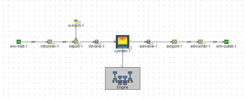
Spark Ignition Engine:
- The spark Ignition Engine is a type of engine where the combustion takes place by generating the spark using a spark plug.
- In this type of engine, the Air-Fuel Mixture enters the engine cylinder through valves and then the fuel is compressed in the compression stroke and finally, a spark is introduced in the cylinder by means of spark plug to ignite the Air-Fuel mixture and hence power is generated in the power stroke.
- Here generally it has a low compression ratio as the fuel used in this type of engine has high octane number. As it has high octane number, the fuel gets ignited by producing spark. In SI engine knocking occurs due to low compression ratio.
- In SI engine, noise-vibration-harness is very low as the pressure conditions inside the cylinder is less when compared to CI engines.
- For SI engines the Air-Fuel Ratio is around 14.5, hence provides very less fuel efficiency for petrol is as fuel.
- Due to lower peak pressure, SI engine is lighter in weight.
- We can achieve high speeds due to light weight and homogeneous combustion.
- Lower thermal efficiency because of the low compression ratio.
CI-Engine Layout:
Compression Ignition Engine:
- The Compression Ignition Engine is a type of engine in which the combustion of fuel takes place by the heat of compressed air.
- In this type of engine, only air is compressed in the engine cylinder after compression the temperature and the pressure of the air are rising up and the sufficient enough to burn the fuel sprayed by the fuel injectors.
- Here it has high compression ratios because of the high ignition temperature of the fuel(diesel).This is because diesel has high cetane number. Hence require high compresssion ratio. Having high compression ratio we can achieve more power.
- In CI engines, noise-vibration-harness is very high as the pressure conditions inside the cylinder is more. This is essential because high pressure helps to ignite the fuel.Also gives less riding comfort.
- For CI engines the Air-Fuel Ratio is greater than 18, hence provides very high fuel efficiency for diesel as fuel.
- Due to higher peak pressure, CI engine is heavier in weight.
- Comparatively low speeds because due to heavy weight and heterogeneous combustion.
- High thermal efficiency because of the high compression ratio.
| SI-Engine | CI-Engine |
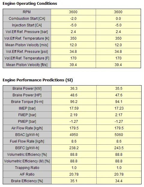
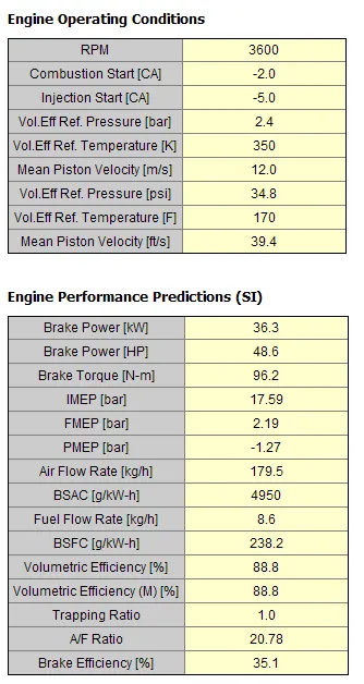
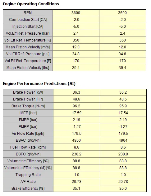
| Break Power = 16.7kW | Break Power = 36.3kW |
| Break Torque= 44.3 N-m | Break Torque= 96.2 N-m |
| A/F ratio= 14.51 | A/F ratio= 20.78 |
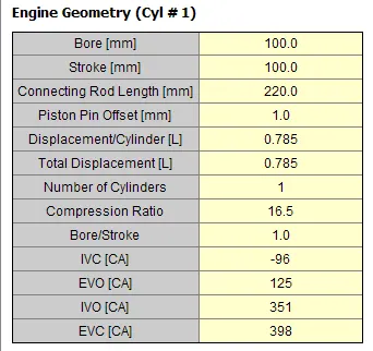
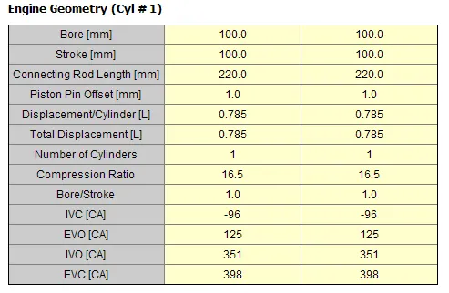
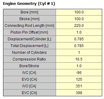
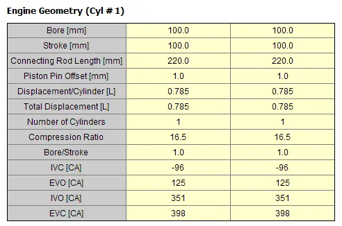
| Compression Ratio= 9.5 | Compression Ratio= 16.5 |
| BSFC= 241.8 g/kW-h | BSFC= 238.2 g/kW-h |
Q. Comments on following parameters.
Break-Specific Fuel Consumption (BSFC):
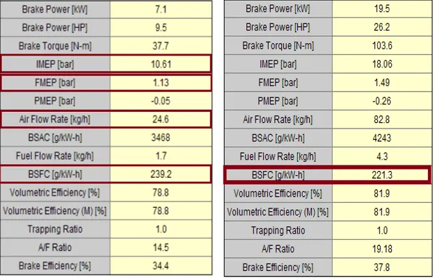
On comparing BSFC value for both SI and CI Engines, it is clear that the the BSFC value for SI Engine is higher. This is because SI-engine operates with a richer air-fuel ratio where as the CI-engine takes a leaner mixture to burn i.e. it has more air then the required fuel.
Exhaust Temperatures:
CI-engines have higher compression ratios,hence they produce high thermal efficiency. As its producing high thermal efficiency, it produces high power outputfor same amount of fuel. Because of very high thermal efficiency and high power output, produces higher temperatures from the cylinder. Due to this CI engines have problem with emissions. In order to minimize the emissions i.e. cooling the exhaust temperatures various after treatment systems like DOC, DPF and SGR are used. These systems help to remove the main pollutant emissions from diesel engine exhaust.
Air/fuel Ratios:
Air-Fuel ratiois the mass ratio of air to a solid, liquid, or gaseous fuel present in a combustion process.
Ratios lower than stiochmetric are considered as Rich. Rich mixtures are less efficient but may produce more power and burn cooler. Ratios higher than stiochmetric are considered as Lean. Lean mixtures are more efficient but may produce higher temperatures.
Q. Change MFB 50 and observe impact on performance.
MFB = Mass Fraction Burnt 50%
MFB is known as the normalized quantity, which explain the combustion process of chemical energy as function of crank angle. Mass Fraction Burnt-50% , it is the position where 50% of fuel-mass is burned over an engine engine cycle is reached. It predicts the effectiveness of the combustion.
SI Engine
For SI Engines MFB-50% is controlled by varying the following parameters;
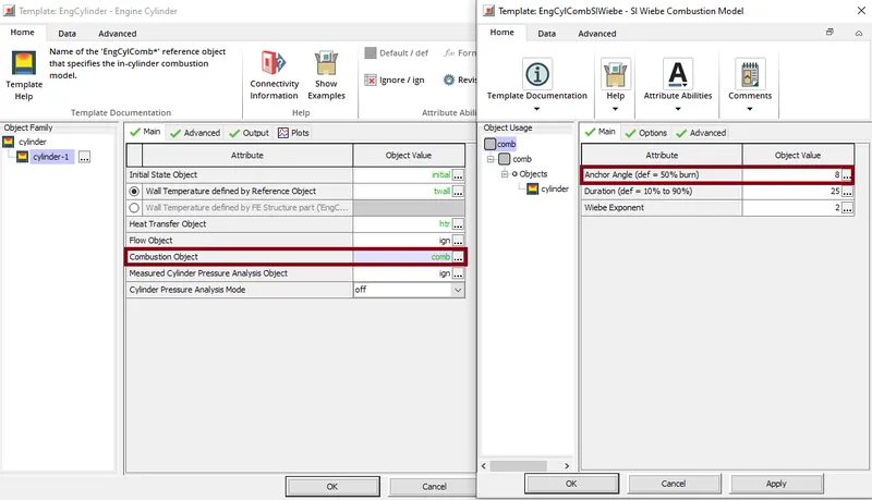
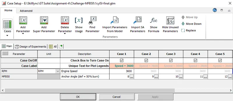
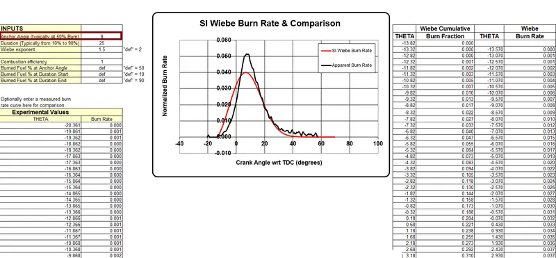
Comparing the SI-Wiebe Burn Rate and Apparent Burn Rate:-
Anchor Angle=8 degree:
Anchor Angle=9 degree:
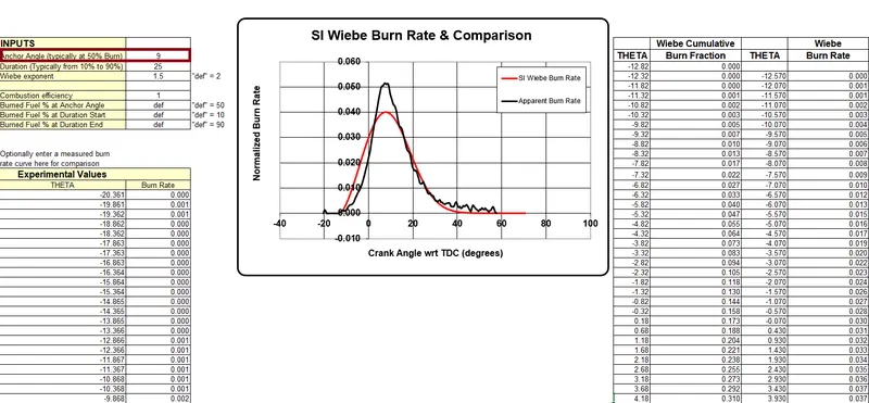
Anchor Angle=10 degree:
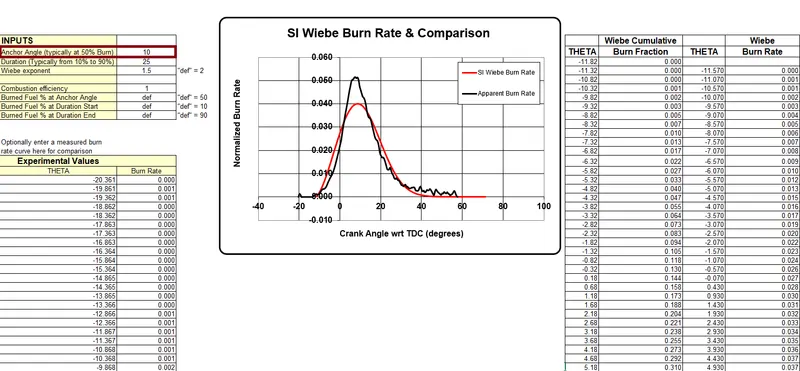
Anchor Angle=11 degree:
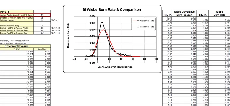
Anchor Angle=12 degree:
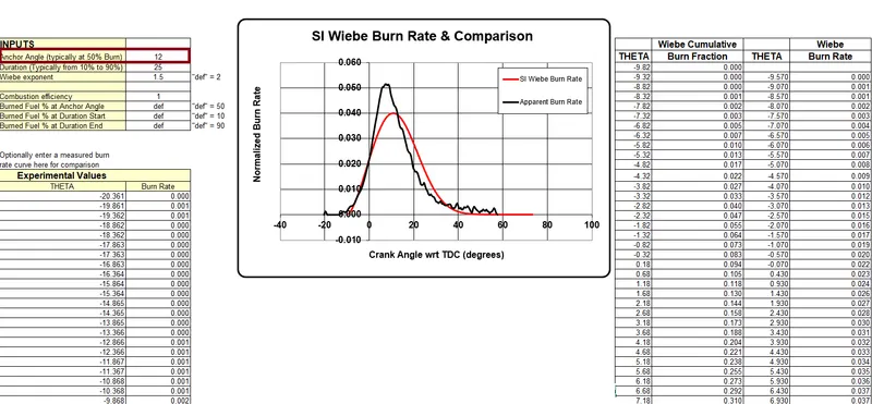
Impact on the performance:
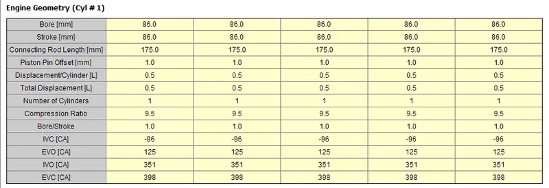
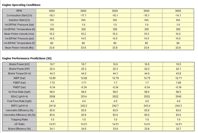
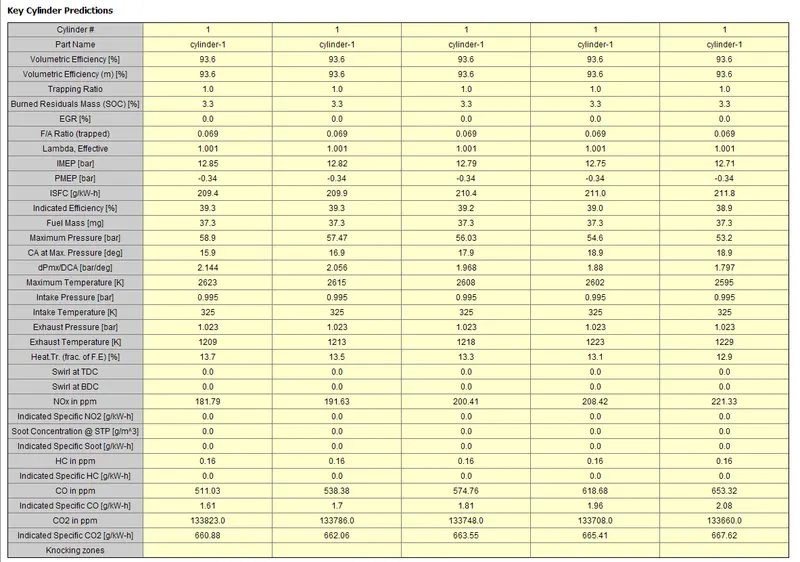
From the above plots, the input parameters like Anchor angle, Duration, Wiebe exponent are constants by which we can change the profile.
Apparent burn rate is determined from the measurments i.e. measuring the pressure vs crank angle we get the burn rate. With reference to this apparent burn rate data we can check the SI Wiebe Burn Rate.
In this case duration=20 and Wiebe exponent= 1.5 is suitable, hene by changing the Anchor Angle we can predicit which angle give more accurate results.On checking for various angles, the most accurate set of parameters are considered as inputs to the SI-model.
The plots show that on varying the anchor angle from 8 to 12 SI Wiebe Burn Rate curve starts shifting towards right. Because of this the ignition time shifts which may lead to delay in combustion process.
From all the plots it is clear that by changing the anchor angle alone we can see that SI Wiebe Burn Rate is not matching to the Apparent Burn Rate. So by changing all the parameters we need to match both the profiles to the closest.
Here after various trials following values are suitable as both profiles are almost following same trend:
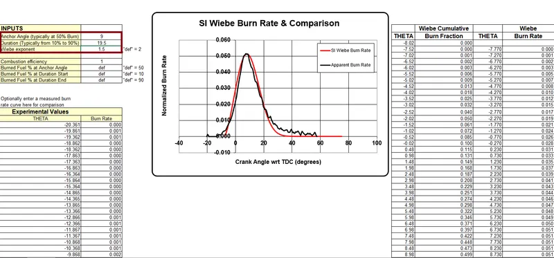
Impact on the performance:
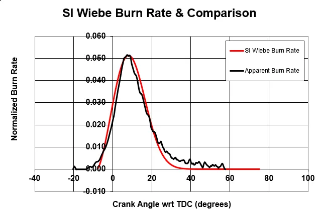
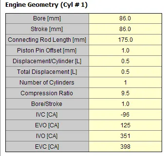
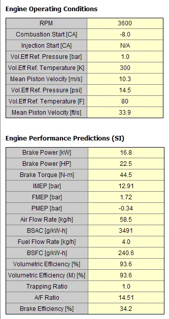
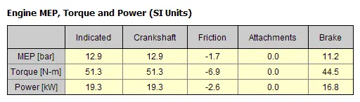
Hence from the above plots we can say that by changing the Anchor Angle, Duration and Duration we could closely match both the curves i.e. SI Webe Burn Rate with the Apparent burn rate. So this is suitable to provide as input.
CI Engine
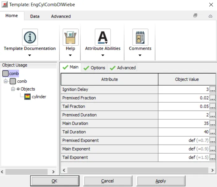
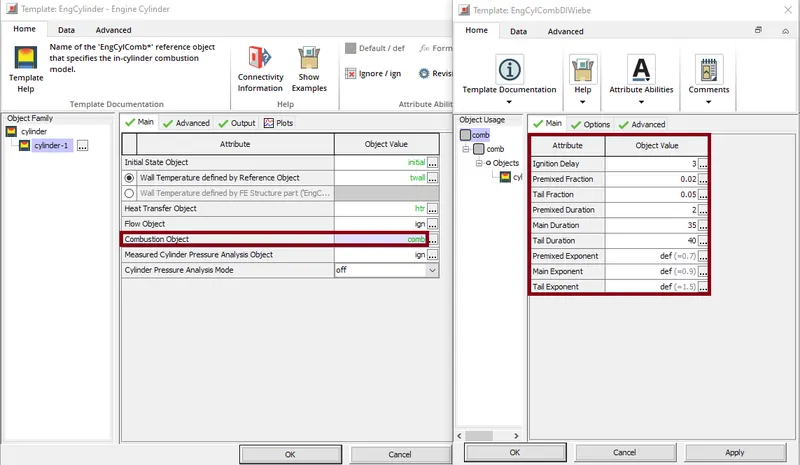
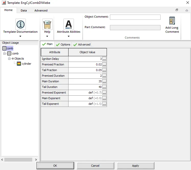
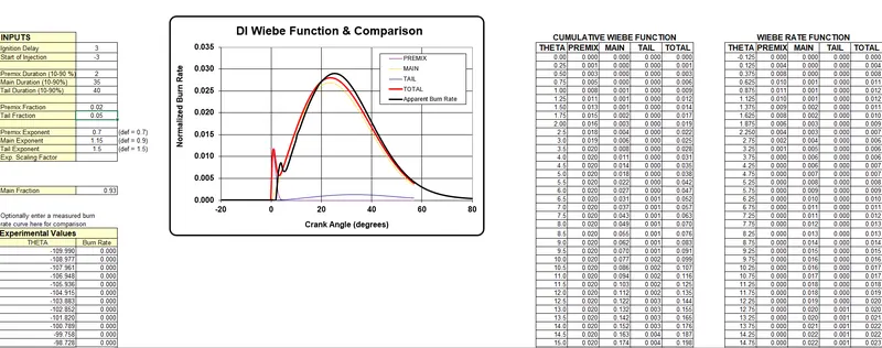
In CI-Engines models various parameters like Ignition delay, Premixed fraction, Main Duration etc are controlled to satisfy MFB50 criteria.
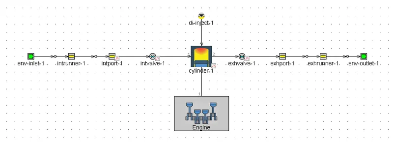
CI-Engine Layout:
The combustion in a CI-Engine is considered to be taking place in four stages:
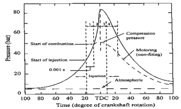
a. Ignition Delay or pre flame combustion
b. Rapid combustion or uncontrolled combustion
c. Controlled Combustion
d. After Burning.
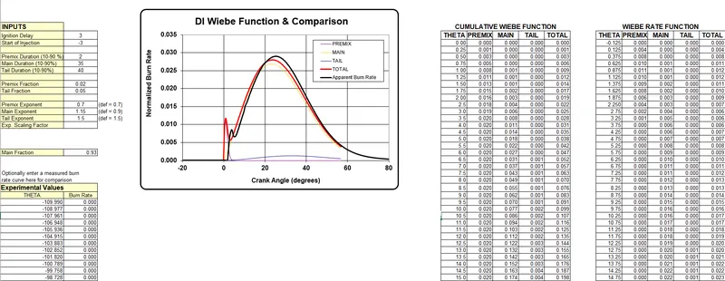
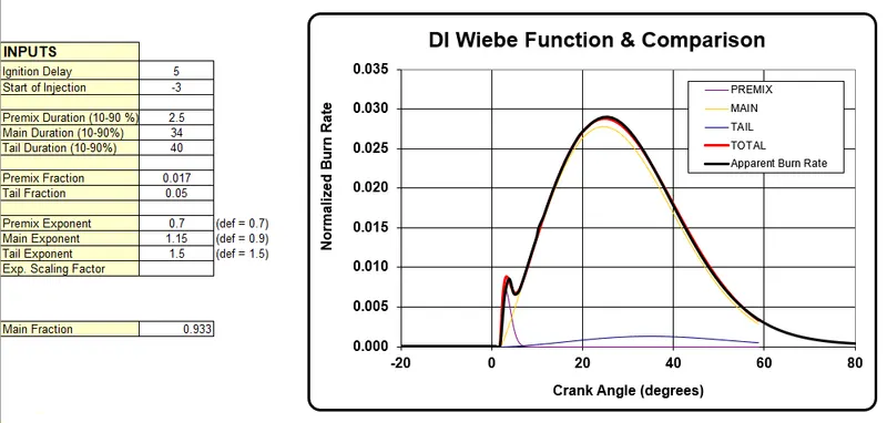
Comparing the CI-Wiebe Burn Rate and Apparent Burn Rate:-
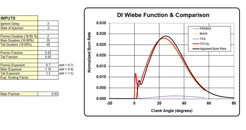
Ignition Delay=3:
Ignition Delay=5:
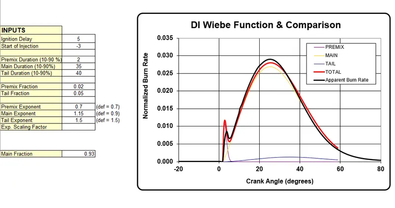
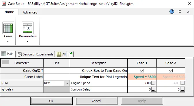
From the above plots we can say that Ignition Delay=5 i.e from changing the crankangle from 3 to 5 we achieved a good fuel burning rate which closely matches the Apparent Burn Model. As we keep increasing the crank angle there will be delay in burning of fuel. If the delay period is larger then in CI-Engine there is knocking.
The results show that, due to the ignition delay there is a reduction of Torque and break power. Also because of increase in Ignition delay we can see that the BSFC value increases.
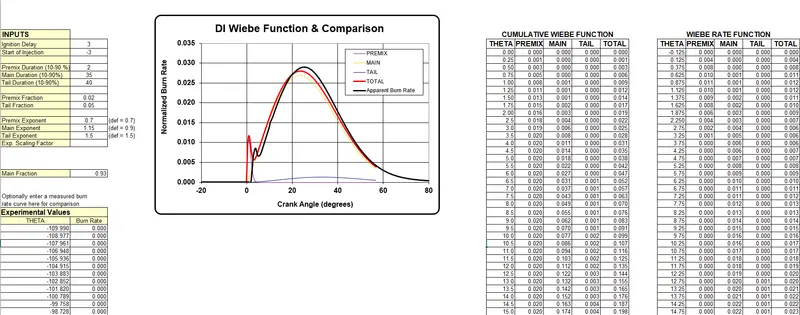
Premixed fraction=0.02
Premixed fraction=0.01
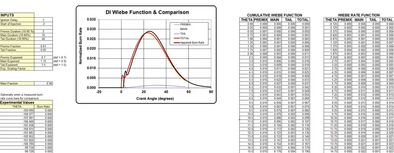
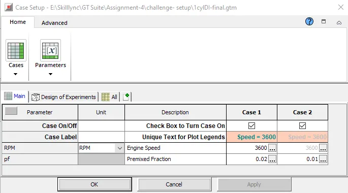
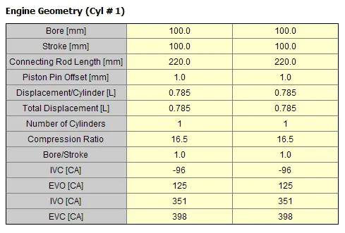
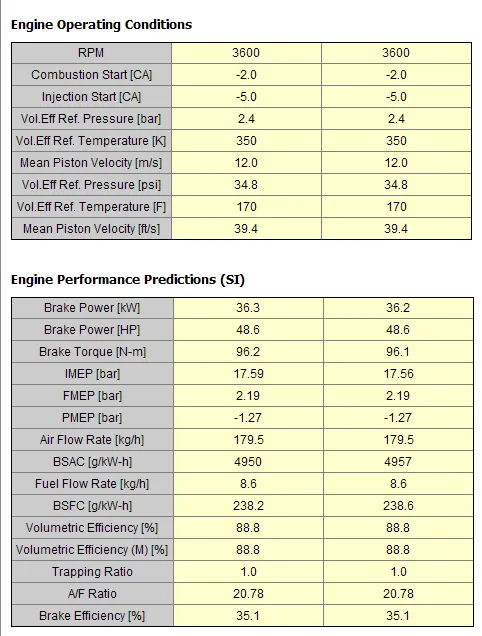
The above plots show that on decreasing premix fraction there is slight decrease in the curve. Comparing both the cases, its clear that the obtained values are very close and there is no effect on the curve.
Premixed Duration:
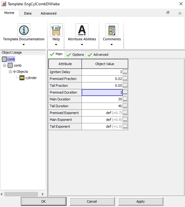
Premixed Duration=2
Tail Fraction:
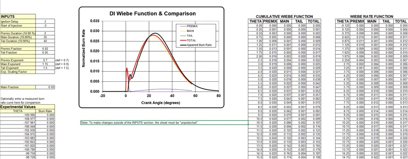
Tail fraction=0.05
Tail fraction=0.07
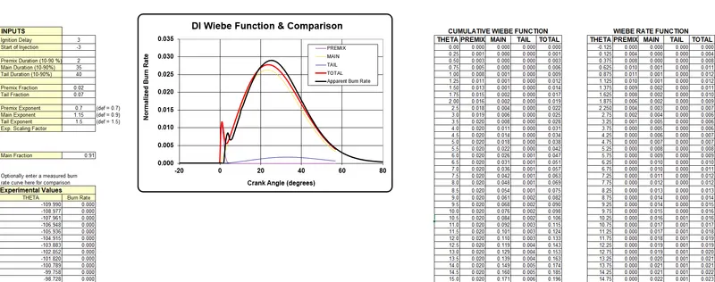
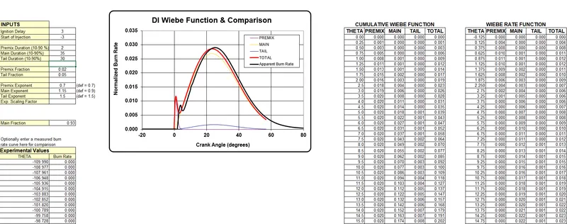
By changing the value of tail fraction there is no much difference in the cure. Hence other parameters are required to modify to obtain the correct trend. The performance parameters i.e. air consumption increase with the increase in tai fraction.
Tail Duration:
Tail Duration=30
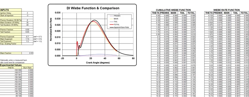
Tail Duration=40
Tail Duration=50
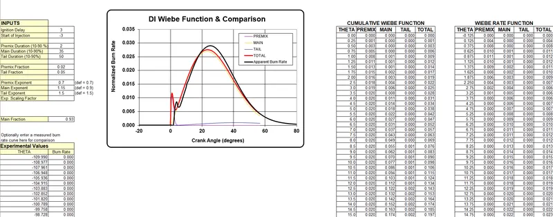
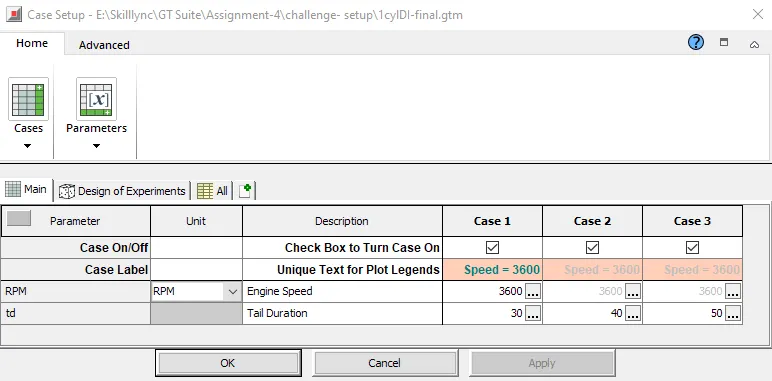
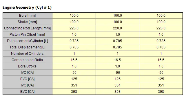
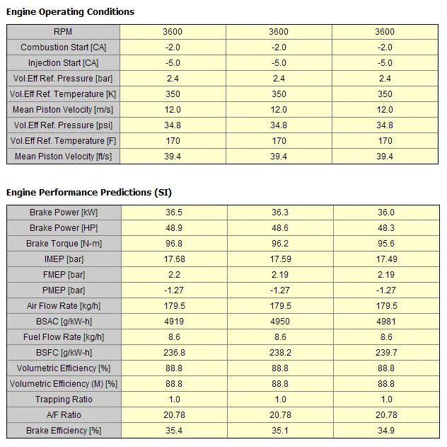
After performing various cases, it is observed that by changing the parameters we could match the Apparent Burn Rate. But before considering these parameters as inputs we need to match bothe profiles so that obtained result will be accurate.
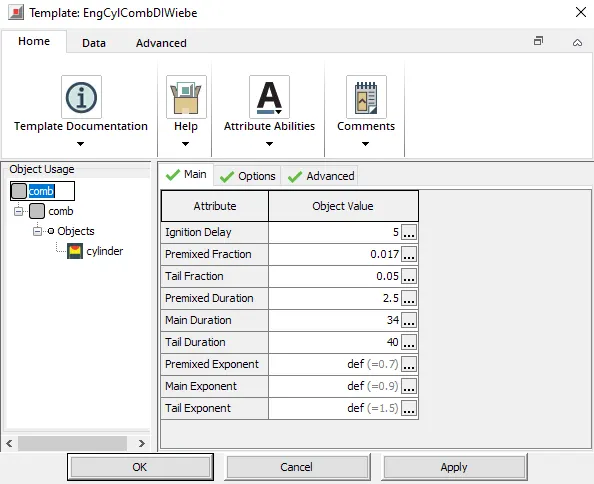
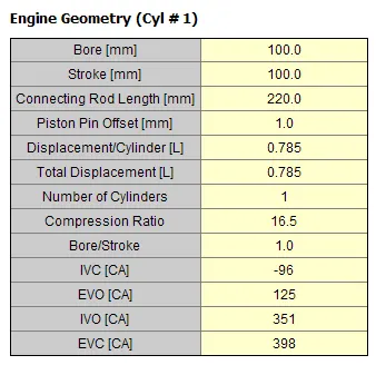
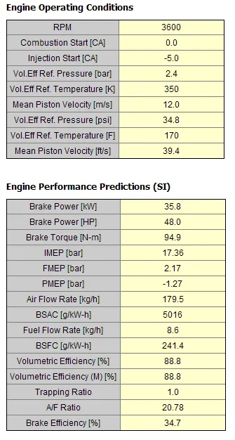
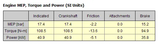
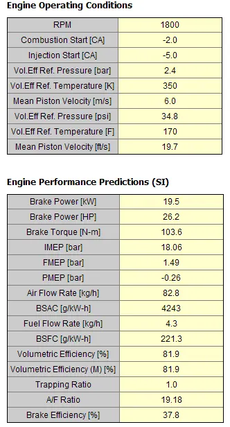
On comparing the obtained results we can see there is a decrease in the Torque and the power but various paramaters like emissions BSFC,BMEP etc are comparitively lower and hence to increase the torque and power we can vary the input parameters as performed in the above cases.
But from the performed simulations we can say that SI-Engine has very few parameters which can be satisfied or matched to the Apparent Burn Rate, where as for CI-Engine we have too many parameters to perform as they are interlinked to eachother.
Conclusion:
- The comparision between SI and CI Engines are done and various important parameters are studied.
- Parameters like BSFC,Exhaust Temperature and A/F ratios are studied.
- Finally, for both SI and CI models MFB50 is changed and the impact on the performance of both models is observed.