Assignment 7-Side Pole Crash Simulation Challenge
Aim :- To perform a side pole crash simulation with the given BIW frame in Radioss and request for outputs as mentioned in problem statement.
Software used :- Altair hyper-works student version 2020 and Hyper-Crash 2020
Problem statement :-
Neon side crash -BIW
- Check unit system and either follow [Mg mm s] or [Kg mm ms].
- Create appropriate interface ,friction 0.2 and recommended parameters.
- Make sure of no penetration and intersections.
- Create rigid wall with friction 0.1 as per referance model.
- Compare the model weight with the referance model and use added masses to reach target weight 700kg while getting CG about the required range.
- Initial velocity as shown in picture.
- Use model checker to ensure good quality.
- Timestep :0.5 to 0.1 microseconds.
- Run 80ms.
Output requests:
- Sectional force in the cross member.
- Intrusion at B-pillar, hinge pillar and fuel tank region. Provide recommendation on what can help to reduce Fuel tank intrusion.
- Peak velocity of inner node of the door.
Introduction :-
In this project, I am working on a Side Crash using the BIW structure. The Side Crash Analysis is important for the occupant as well as passenger safety. If the holding structure is not good, all the impact force may travel into the main compartment and this leads to injured the occupant.
Crash analysis is an integral part of safety analysis and is often completed at intersections and corridors. The crash analysis can help assess concerns and help determine potential improvement options. A Crash test is a form of destructive testing usually performed in order to ensure safe design standards.
New Car Assessment Program (NCAP):
It is a government car safety program tasked with evaluating new automobile designs for performance against various safety threats.
Standard crash tests performed by NCAP:
1: Frontal offset testing (64 km/h proposed)
2.Side-impact testing
3.Pedestrian protection testing
4.Rear impact testing
5.Child dummy dynamic crash testing
FMVSS ( Federal Motor Vehicle safety standards)
Federal Motor Vehicle Safety Standards (FMVSS) are US federal Vehicle Regulations specifying design, construction, performance, and durability requirements for motor vehicles and regulated Automobile safety-related components, systems, and design features. They are the U.S. counterpart to the UN Regulations developed by the World Forum For Harmonization of Vehicle Regulations and recognized to a varying degree by most countries except the United States.
BIW (BODY IN WHITE)
Body in white (BIW) is the stage in Automobile Manufacturing in which a car body's frame has been joined together, that is before painting and before the motor, chassis sub-assemblies, or trim (glass, door locks/handles, seats, upholstery, electronics, etc.) have been integrated into the structure. Assembly involves different techniques such as Welding (spot, MIG/MAG), Riveting, clinching, bonding, and laser Brazing.
Solution :-
Step 1 :- Intersection and penetration checking :-
- Before opening model check units for further results from starter input file.
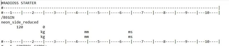
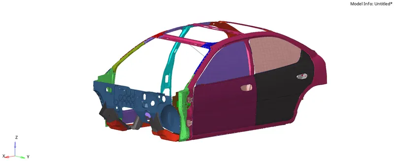
- 2. Import the given model "neon_side_reduced_0000" into Hypermesh GUI.
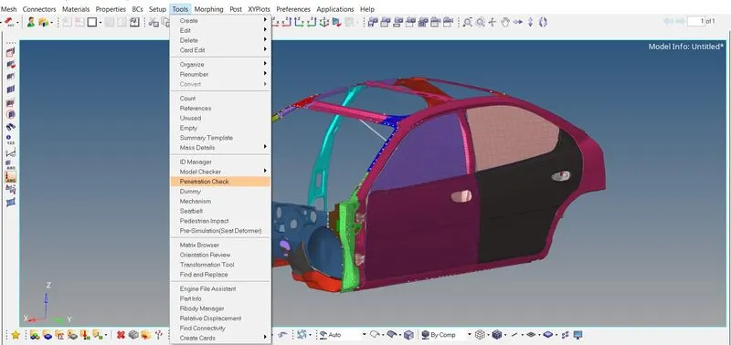
- To check for penetrations in the model, we will go to Toolsmenu on Menu bar and click on Penetration Checkoption. In Penetration check panel, we will select all the components and click on Check command. The software will check for penetrations and then display the results as shown below,
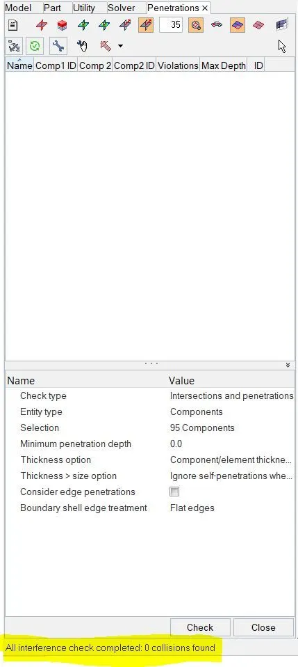
There are no penetration or intersection error found.
Step 2: - Balancing COG: -
- The BIW model doesn't consist of the exact weight of the vehicle so Additional mass should be added to the BIW model considering the weight of the Body after manufactures e.g. with the weight of the seats, the weight of the persons and all other weights in realistic condition.
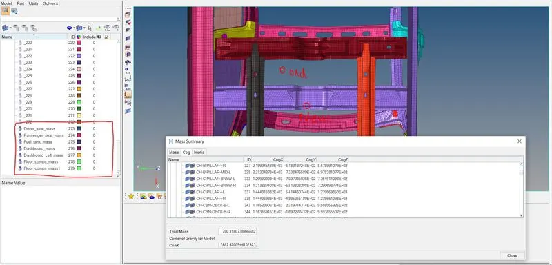
- The targeted weight is given 700kg where the actual mass before adding external weight is 166kg.
- To Add the mass, Click on added mass, and to create a new object Select Type0 - Mass is distributed to each node of the node group, and click save
- Check COG, simultaneously after giving the mass in the balancing menu.
- Add mass according to the needs till the point reaches the centre and till the mass attains the target value. Below, image show that COG is present on required location i.e. under the driver seat.
Step 3: - Creating contact surfaces.
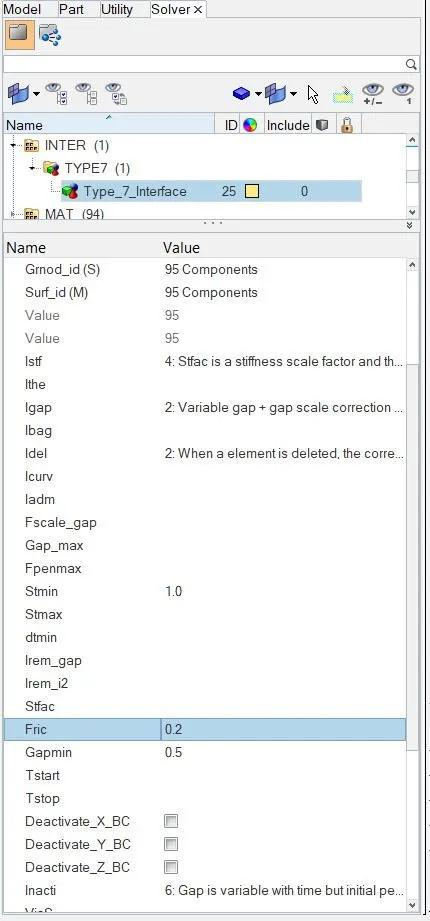
- A contact interface should be defined to view the contact energy. Here the type-7 Contact is used (Node to Surface), because of its high accuracy and correct physical representation. The self-impact is defined in the Contact interface as the body acts as both master and Slave.
- Interface properties Changed to recommended conditions as per mentioned in problem statement and create another interface for bumper and rail contacts. which is shown in image below.
Step 4 : - Rigid wall
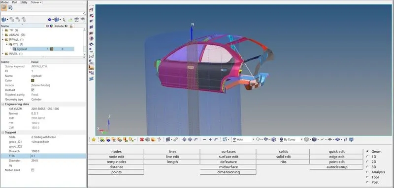
To create a cylindrical rigid wall at the left side of the car, we will need the outermost node at the front left door of the car. So we will create the outermost node on the element edge using temp nodes option. Then we will right click in solver browser and navigate to Create > RWALL > CYL. In the RWALL panel, under Engineering data we will specify the coordinates of the pole which will be at some distance from the outermost node on side door. Then we will give the normal direction to the pole in Z-axis and diameter of the pole to be 254 mm. The FRIC value will be 0.1 and Dsearch value will be 1000 as shown below.
Step 5 :- Initial velocity :-
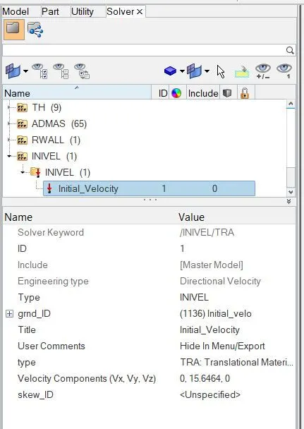
- In this simulation the initial velocity given to the model is 35Mph or 15.6464 mm/ms.
- To set the initial velocity of the model LoadCase>Initial Velocity>Set the value of the velocity in Y-Direction>Select all nodes>Yes>Save
Step 6 :- Section creation. :-
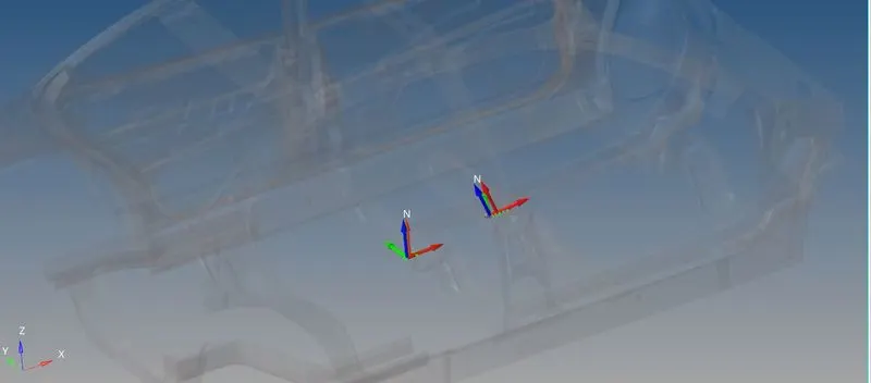
- 1. The results which we want on required cross sectional parts will be calculated based on a frame of reference. So before creating cross section, we will create moving frames on a particular node of that section. Now as we have to create the moving frames which are also called as local axis, we have to perfectly align our local axis to the global axis.
- 2. Now we can create moving frame using these nodes. In Solver browser, we will right click and navigate to Create > FRAME > MOV. So here, we will create frame by node reference and select the nodes for x-axis and xy plane and then click on create.
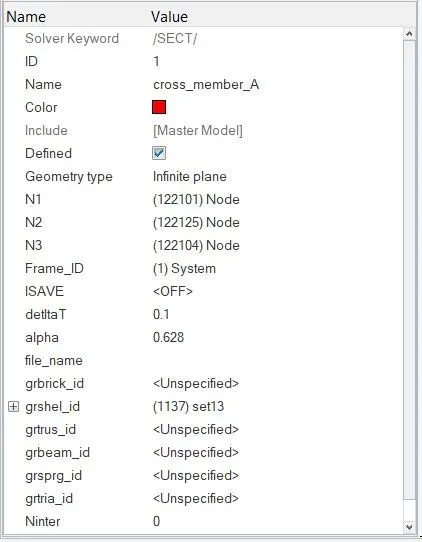
- 3. Thus a moving frame will be created. Now we will create cross section for this frame. To create a cross section, we will right click on the Solver browser and navigate to Create > SECT > SECT. In section panel, we will specify the Frame_ID as the moving frame which we created and delta value as 0.1. From Hyperworks help menu, we get that the general value of alpha is taken as 2π102π10 . Thus we will specify alpha as 0.628. We will right click and create grshel_id, then we will select the elements where we want the cross sectional results. Thus the cross section will be created as follows.
Step 7 :- Run model checker to ensure good quality
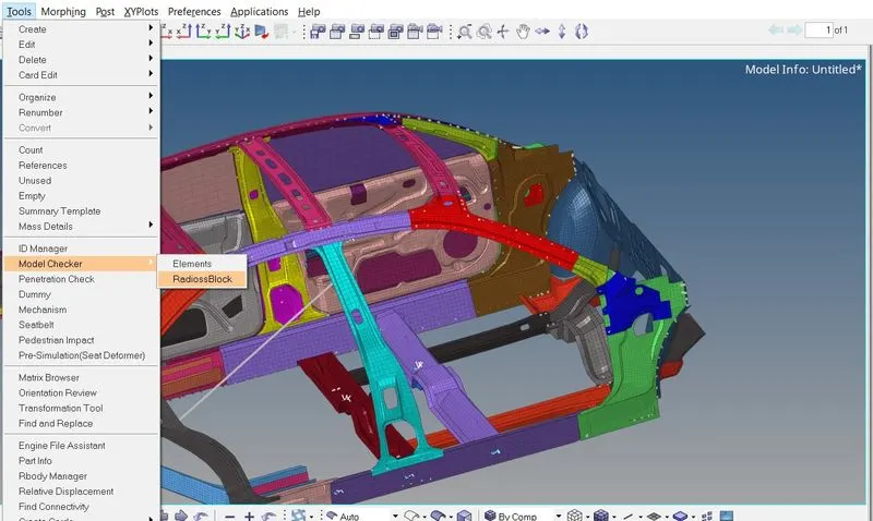
To check the quality of the model in Hypermesh, in Menu Bar we will navigate to Tools > Model Checker > RadiossBlock. This will open a new Model Checker browser.
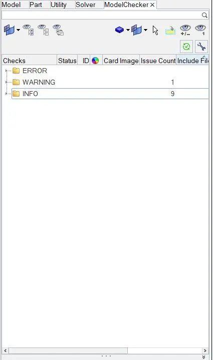
In this browser, we will click on Run checks command which is at the top right side in the above figure, indicated in red box. After running the checks, we get zero errors only warning are shown we can ignore these warnings and move further. From above figure, we can ensure that the quality of the model is good for simulation.
Step 8 :- Set time step and runtime
To check these parameters in Hypermesh, we will navigate to Cards under Model browser. To check the run time, we will open ENG_RUN card where we will see that the model already have the run time in Tstop as 80 ms. For the time step, we will open ENG_DT_NODA card and we will change the Tmin value to 0.5 ms.
Step 9 :- Output request
- Peak velocity of inner node of the door.
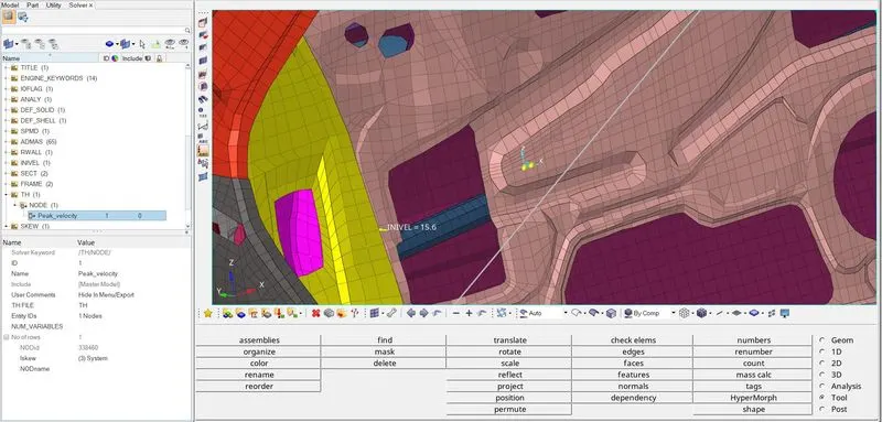
To find peak velocity at the inner node of the door, we will create a moving frame at the node location by using the same procedure as we used in cross section creation. Then we will create output block for the peak velocity by specifying the node and the frame or skew based on which the peak velocity is calculated as shown below.
- Intrusions at B-pillar, hinge pillar and fuel tank :-
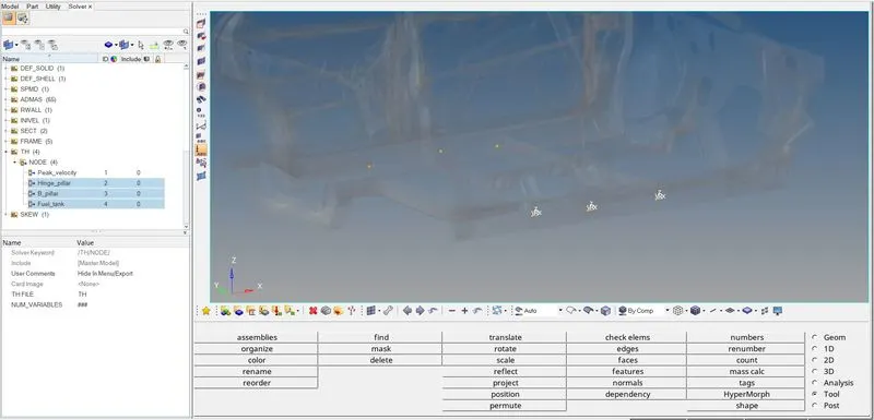
Here, we need to find the intrusions at B-pillar, hinge pillar and fuel tank. So to find the results at the specified parts, we need to have a frame of reference. Thus we will create moving frames at the opposite side which are at right B-pillar, hinge pillar right side and fuel tank opposite side as shown below.
- Sectional forces in cross members
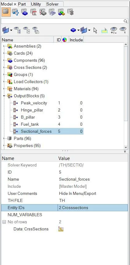
For this we will go to Output Blocks under Model browser. Then we will right click and create a new output block. Under Entity IDs option, we will select the cross section which we created and thus we will be able to plot graphs of the cross-sectional forces in Hypergraph.
RUN THE SIMULATION:
- Click on the analysis panel in the Hyper mesh.
- Save the model in the local directory.
- Type -nt 4 in option and click on Radioss.

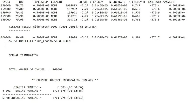
From side_crash_0001.out file, the Total number of cycle was 160001. The energy error is -2.2% which is in acceptable limit. The mass error is 0.05091% which also less than 5% it is acceptable. The run was “normal terminated’ which implies the processor successfully completed. There was no sudden changed in energy as well as in error. as shown below
Simulation in Hyperview:
Animation of the crash simulation is as follows:
Displacement contour plot :-
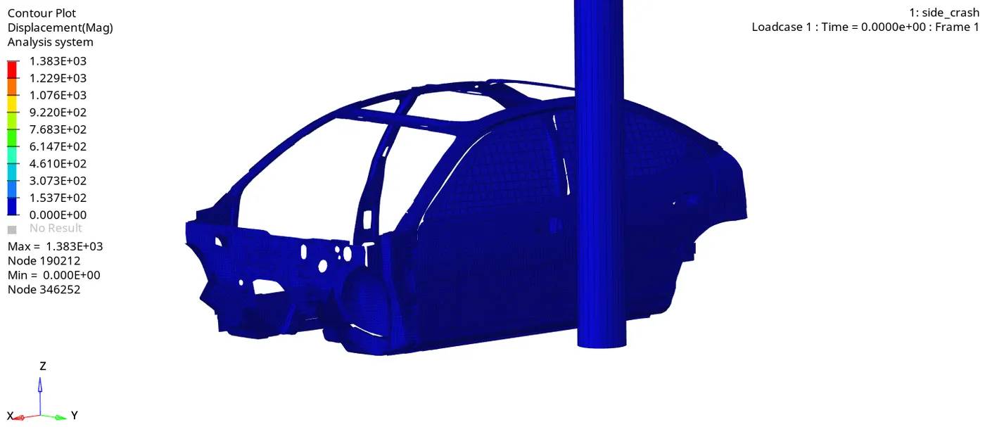
In the above crash simulation of the vehicle, we can see the vehicle body is impacting on a Pole. After the impact, the frame of the vehicle deforms and the vehicle body gets contracted around the pole with left B-Pillar as the pivot point. The CG of the vehicle is in the same axis or direction of the pole, so we can see even deformation of the frame around the pole.
Von mises stress :-
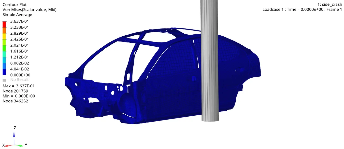
the stress is more in B-pillar and cross members as B-pillar takes the initial impact and then the impact is transferred to the cross members.
Plots in Hyperview 2D :
The plots like energy differences, displacements, velocity and the normal forces are analysed.
TOTAL ENERGY OF THE SYSTEM:
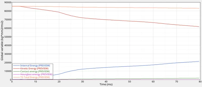
From the above plot, we can see that there is high amount of Kinetic energy at the start of the simulation but as the simulation progresses, the kinetic energy in the vehicle decreases and gets converted into internal energy, so the internal energy increases in the same proportion. Thus the total energy in the system is almost constant at 85000 kg*mm2/ms2 and due to some energy loss which we can see in energy error, there is some decrease in total energy. We can also see some amount of contact energy in the model as we have defined the value of friction in Type 7 interface due to which contact energy is generated.
Sectional forces acting in cross members :-
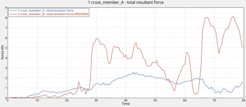
From the above plot, we can see that the total resultant force in the rear cross member is more than the cross-member A. As the cross-member B is in line with the Pole, it experiences more force.
Intrusions :-
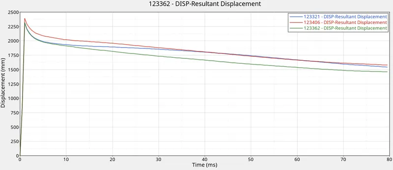
Blue line- Intrusion node at Hinge pillar
Red line- Intrusion node at B-pillar
Green line- Intrusion node at fuel tank
- Intrusion at Hinge Pillar – The final displacement at Hinge Pillar region is 1542.62 mm and the initial distance of fuel tank from frame of reference is 1310.62 So total intrusion is 1310.62 – 1542.62 = -232.00 mm. Thus the total intrusion at hinge pillar region is 232 mm but the minus sign indicates that the intrusion is increased after the crash.
- Intrusion at B-Pillar – The final displacement of node at B-pillar is 1577.81 mm and the initial distance of fuel tank from frame of reference is 1319.49 So total intrusion is 1319.49 - 1577.81 = -258.32 mm. Thus the total intrusion at B-pillar region is 258.32 mm but the minus sign indicates that the intrusion is increased after the crash.
- Intrusion at Fuel Tank – The final displacement at fuel tank region is 1462.31 mm and the initial distance of fuel tank from frame of reference is 1319.97. So total intrusion is 1319.97 – 1462.31 = -142.34 Thus the total intrusion at fuel tank region is 142.34 mm but the minus sign indicates that the intrusion is increased after the crash. This increase of intrusion can lead to failure of fuel tank and fuel may drop out of the tank. To prevent this failure, we need to reduce the intrusion which we can achieve by adding another cross member in fuel tank region which absorb some energy and resist the movement of fuel tank region and also the cross member can take some deformation. Also we can increase the strength of the support element near the Fuel tank region by changing the material or by adding a small support bracket over that region
Peak velocity of inner node of door :-
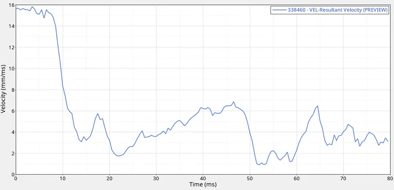
This plot helps to understand, with how much the actual inner side of the door moves in the direction of the Driver during the pole impact. The peak Velocity measure at the inner door point is 15.84mm/ms till 8 ms. after that, the speed is starting to reduce to a great extent.
CONCLUSION :
Thus, the model was simulated for a side pole crash test and the results were discussed. From the output file the energy error and mass error is in an acceptable range so I can conclude that the simulation is pretty stable. Cross-members A and B are playing important role in the Impact force absorption. So, improving the cross-member material or adding some extra support element near the cross member can improve their performance, also for the Fuel tank side as we discuss earlier need some reinforcement. We can also work on the B-pillar property improvement as it's the closest part which is comes in the contact with the force during the side crash.