Assignment 7-Side Pole Crash Simulation Challenge
SIDE CRASH SIMULATION ON CAR BIW COMPONENT
AIM: To run a simulation on side crash of car BIW component and to extract results on crash Body In White component.
OBJECTIVES:
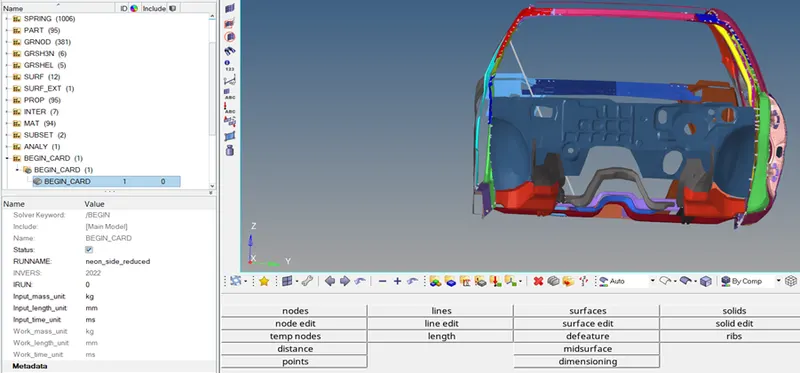
- Check unit system and either follow [Mg mm s] or [Kg mm ms].
- Create appropriate interface, friction 0.2 and recommended parameters.
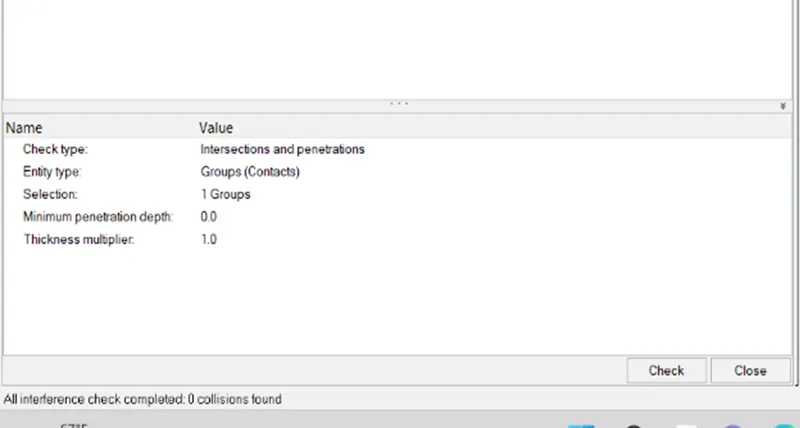
- Make sure of no penetrations and intersection.
- Create rigid wall with friction 0.1.
- Compare the model weight with the full scale 300k nodes model and use added masses to reach target weight 700kg while getting CG about the required range.
- Initial velocity 20 mph.
- Use model checker to ensure good quality.
- Time-step :0.5 to 0.1 microseconds.
- Run 80 ms.
OUTPUT REQUESTS:
- Sectional force in the cross member.
- Intrusion at B pillar, hinge pillar and fuel tank region. Provide recommendations on what can help to reduce Fuel tank intrusion.
- Peak velocity of an inner node of the door.
CASE 1:
CHECK UNITS:
CASE 2:
CREATE INTERFACE:
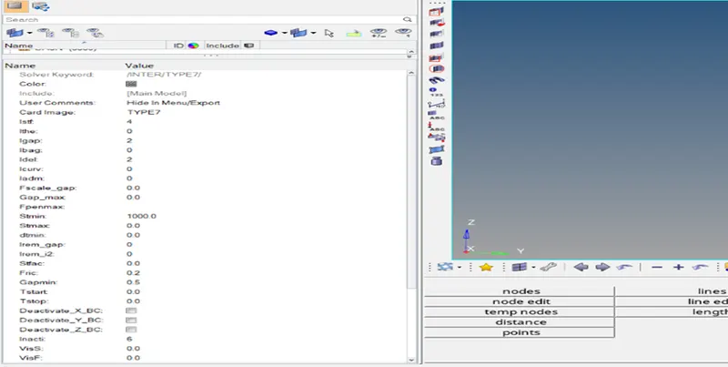
- In these we used type 7 contact which is surface to node contact, as master and node are collide each other we call it self contact type.
- Proper values are need to be given in order to do proper interface.
- Select all the master nodes and slave nodes of components and give values of istf ,igap , idel ,stmin,fric,gapmin,inacti,iform.
CASE 3:
PENETRATION CHECKS:
- As there are no penetrations and collisions we are good to go.
CASE 4:
RIGID BODY CORRECTIONS:
- As this is crash analysis we don’t need to check for rigid bodies as we are going to study of deformation.
CASE 5:
RIGID WALL WITH FRICTION=0.1.
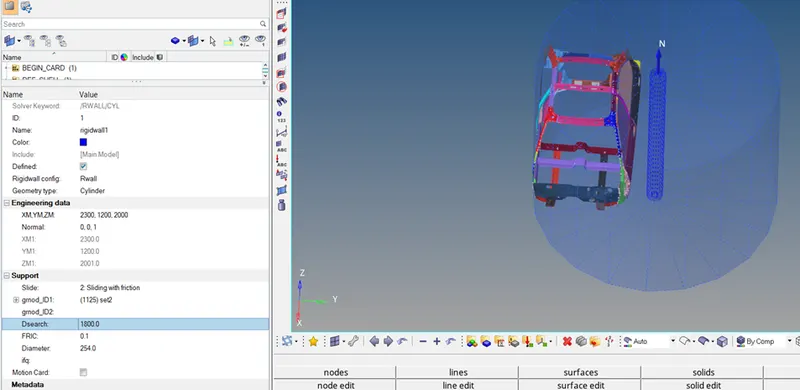
- We need to create wall to perform crash analysis, with friction 0.1.
- To create a rigid wall first we need to create the node on B PILLER.
- After creation of node we need to give coordinates of that node .
- We need to give normal as 1 so that the crash will happened in the direction we want.
CASE 6
MODEL COMPARISON WITH MASSES.
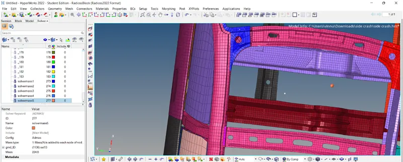
ABOVE FIGURE COG BEFORE ADDING MASSES.
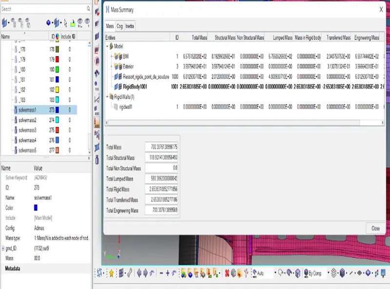
TOTAL MASS ADDED 700
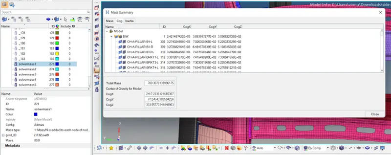
COG COORDINATES
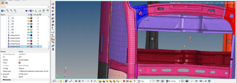
COG AFTER MASS ADDITION
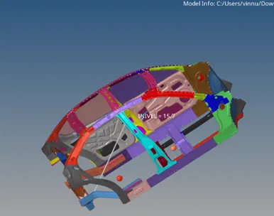
MASS ADDED LOCATATIONS
- First we need to locate center of gravity of the model
- We can find it in the tools options COG then we can find the center of gravity node with coordinates.
- Then if we find that is not at the center we need to make it to the center of the chasis frame by adding mases.
- The below pictures are details of mass and COG after adding the masses to the car frame.
- So we need total structural mass we need is 700kg.
- So that there is a balance so that cog will be at centre.
- These are the markings of nodes of added masses to them so that it reaches to 700kg.
- Mass added all over the body at driver and passenger seats,fuel tank, cross members.
CASE 7
INITIAL VELOCITY.
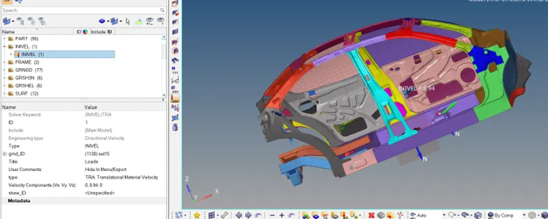
- Go to solver browser > Right-click > create > boundary conditions > INIVEL,
- Select all the nodes present in the model.
- Give an initial velocity of 20 MPH when we convert it 8.94 (mm/ms) in a positive Y-direction.
- FMVSS (FEDERAL MOTOR VEHICLE SAFETY STANDARDS) based on that standards 20 mph is given as the initial velocity.
CASE 8
TIME STEPS
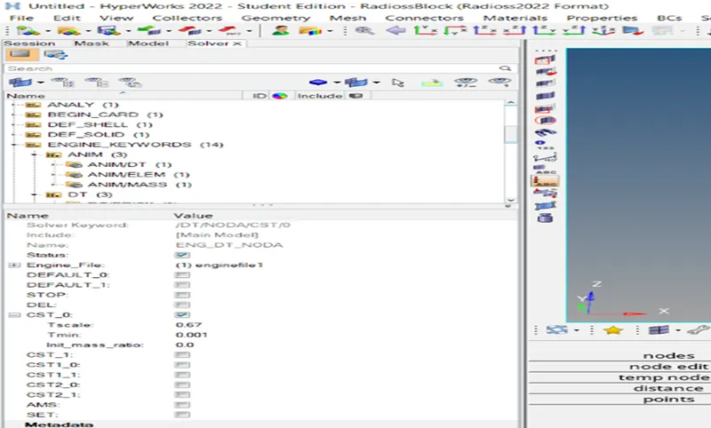
TIME STEP DT NODA VALUES
- We will run the time step 0.5to 0.1 microseconds
- For these we need to select engine file and DT- NODA
- The run time will be for 80ms.
- Tstop will be 80ms in engine run file settings.
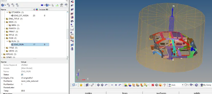
TSTOP RUN FILE
CASE 9
SECTIONAL FORCES ON CROSS MEMBER 1 AND 2
- We need to create sectional forces on cross member to observe forces on the cross members.
- We need to select that node and create coordinates at that particular node .This is done so that to record reaction forces on the cross members of chassis model.
- To capture forces we need to create moving frame and crosssections on the rails and rest of the parts of the chasis frame.
- We need to create moving frames on the rails, with the help of local coordinates we need to provide orgin , x and y axis.
- After creating moving frame we need to create crosssections by selecting moving frame coordinates to the cross members.
- In that way we create all the cross sections on all over the BIW chasis frame.
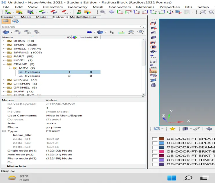
MOVING FRAME
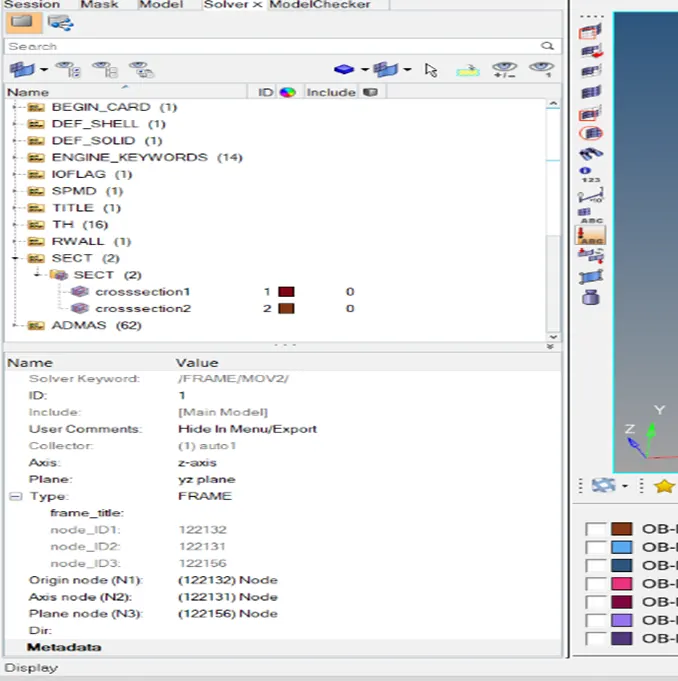
CREATING CROSS SECTIONS
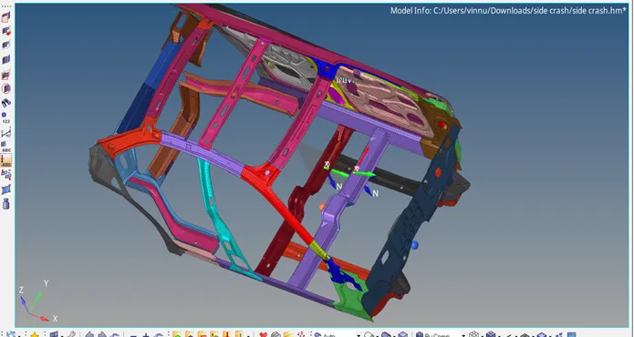
CROSS SECTIONS
CASE 10
PEAK VELOCITY
- We need to create node on the door .
- After that we need to create TH file for that node.
- so that we will note peak velocitiy of that node at certain time.
CASE 11
INTRUSIONS
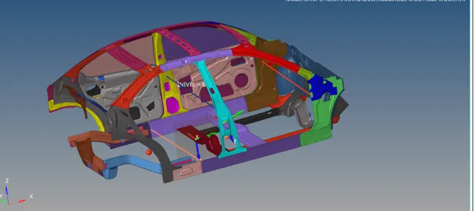
- These intrusions are used to calculate the rate of deformation of hinge side,b piller , fuel tank .
- So we will create 1d springs to the following locations .
- So we will create 3 springs for 3 locatations.
- For these springs we will provide proper 1d element properties.
- we need to create TH file for intrusions to observe rate of deformation on the chasis
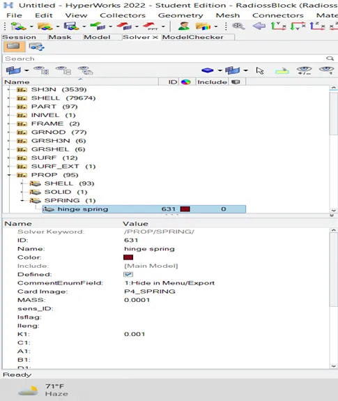
INTRUSION SPRING PROPERTIES
CASE 12
OUTPUT BLOCKS
- These are used to create TH (time history ) for every loads we created.
- These output blocks will give proper output visualization and we can analise every loads on chasis with respect to time.
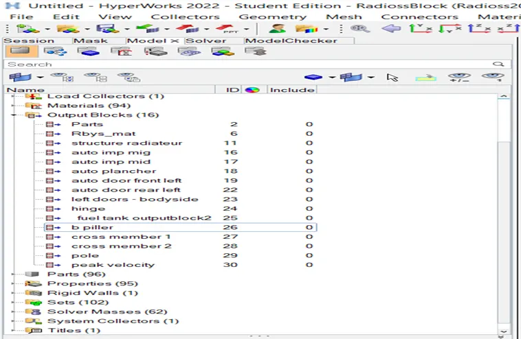
OUTPUT BLOCKS
CASE 13
RESULTS
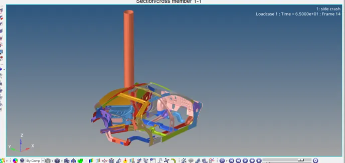
- H3D file is from above figure after the whole simulation is done to visualise the reactions of the model we need to import the H3D file from respected folder.
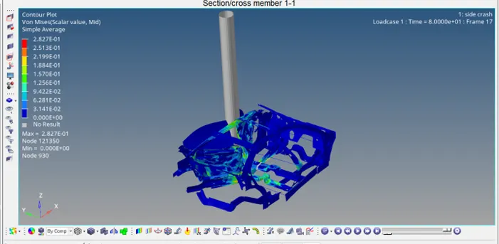
VONMISES STRESS
- In these we will plot vonmises stress to know the areas of stress points.
- We got some stress points so that highest stress point got at the max stress at 2.827E-01 node no 121350.
SECTIONAL FORCE ON CROSS MEMBERS
- The two graphs from above are sectional forces on rails.
- Compare to the both the graphs the rail on the crossection got highest forces on it.
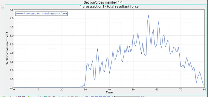
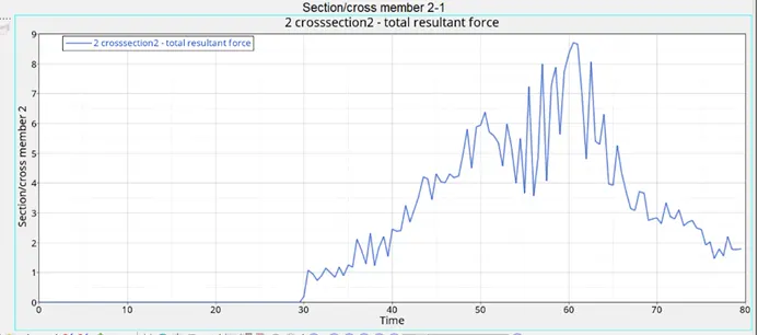
- In the above graphs when we compare both the forces on cross members cross member 2 got highest forces which is nearer to the b piller.
- In the crossmember 2 at exactly at 60 ms it got highest value of force in the crossmember.
- These crossmember plays a crucial role in resisting of crash of the car body.
- Especially for the side crash cross members plays vital role to protect car body crash and also it leads to prevention of accident damge to driver seat.
INTRUSIONS
- Intrusions on the hinge , bpiller, fuel tank are applied these are major locatations to look in side crash.
- The elongation will result largest deformation forces by crashing the rigid wall.
- This is done because of the safety measurement taken with respect to passenger.
- So we will create 3 springs as 1D ELEMENTS at 3 locatations at hinge, b piller , fuel tank.
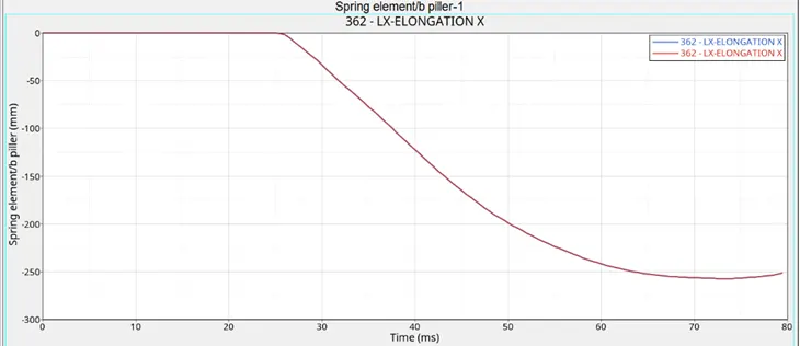
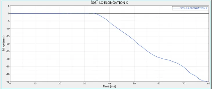
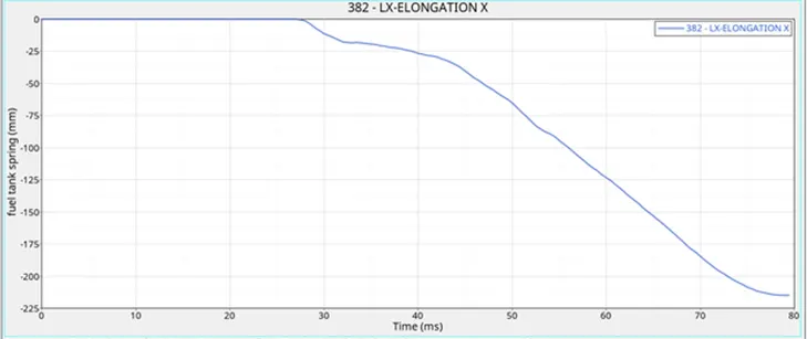
- So from above graphs when compared to 3 of them b piller got highest deformatation .
- b piller got 250mm, fuel tank got 213mm, hinge got 45mm.
- As this is side crash we need hinge did not get deformatation , major side of the crash pole is nearer to the b piller.
WAY TO DECREASE INTRUSION DEFORMATATION ON FUEL TANK :
- We can add another crossmember to prevent from deformation,because cross members prevents from deformatations they observe lot of impact.
- we can use proper materials like composite materials can cause less deformations.
- we can use materials with high yield strength,stiffness properties can bring good results.
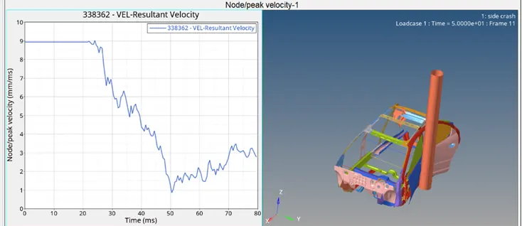
PEAK VELOCITY:
- We need to assign a node on the driver door to record highest velocity .
- AT initial stages velocity is 8.94 mm/ms as per the initial value.
- when the node hits door it reaches the velocity down to wards the driver seat meanwhile velocity also reaches down.
ENERGY ERRORS AND MASS ERRORS
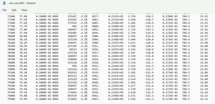
- The energy error and mass error are -2.2%and mass error is 0.23 which is acceptable.
ERRORS AND WARNINGS
- I got most of the warnings during simulatations
- I got null mass error I forgot give mass value for the springs
- There are unused properties which got which are not assigned when i gave value it got rectified.
- Another one is variable no warning when I gave the numbers to the forces it got rectified.
KINETIC ENERGY:
- To get proper kinetic energy value we need to apply proper mass around the chasis after assigning 700 kg of mass.
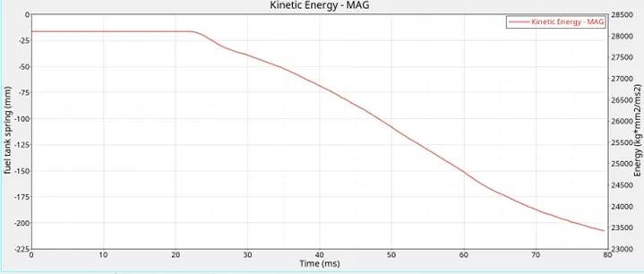
- At intial stage the kinetic energy is 27,973 after 80 ms it reached to 23,300.
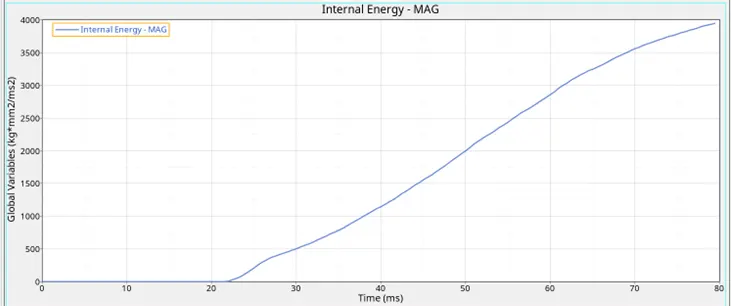
INTERNAL ENERGY:
- After 80 ms of the internal energy raised to 4000 due to high impact and large deformations.
CONCLUSIONS
- WE got better results in side crash all we need is to protect driver from accident .
- To get better and accurate results meshing should be proper.
- All the forces recorded but the recorded forces different from others.
- The crash also depends on perfect balance of masses and COG of the model.
- Perfect mass and cog will get better realistic deformations.
- The deformations got is quite natural for the initial velocity based on (fmvss) standards.