Assignment 7-Side Pole Crash Simulation Challenge
AIM:- TO PERFORM A SIDE CRASH SIMULATION WITH THE GIVEN BIW FRAME IN RADIOSS AND REQUEST FOR OUTPUT AS MENTIONED IN PROBLEM STATEMENT.
Question:
Neon side crash -BIW
- Check unit system and either follow [Mg mm s] or [Kg mm ms].
- Create appropriate interface ,friction 0.2 and recommended parameters.
- Make sure of no penetration and intersections.
- Create rigid wall with friction 0.1 as per referance model.
- Compare the model weight with the referance model and use added masses to reach target weight 700kg while getting CG about the required range.
- Initial velocity as shown in picture.
- Use model checker to ensure good quality.
- Timestep :0.5 to 0.1 microseconds.
- Run 80ms.
Output requests:
- Sectional force in the cross member.
- Intrusion at B pillar,hinge pillar and fuel tank region.Provide recommendation on what can help to reduce Fuel tank intrusion.
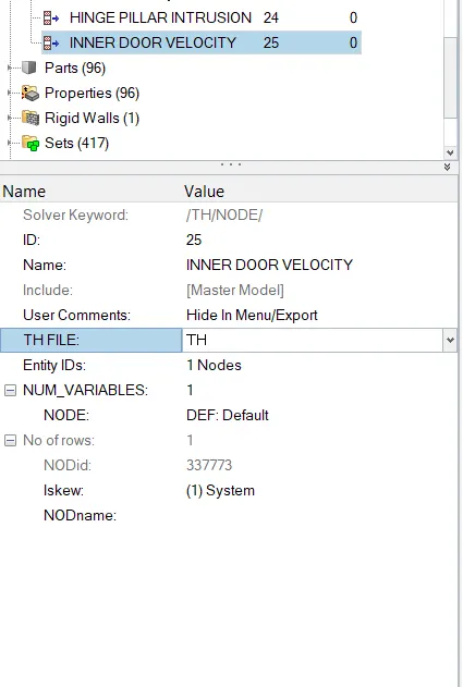
- Peak velocity of inner node of the door.
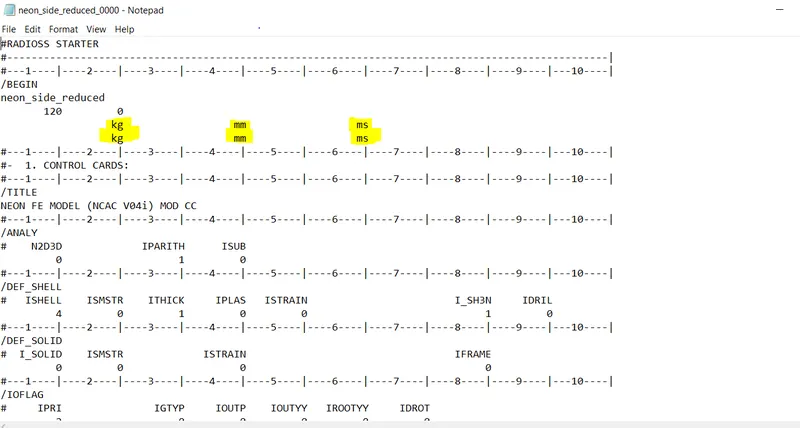
CHECK FOR UNIT SYSTEM:-
- In order to check the unit system of the model open the Neon_front_0000.rad file.
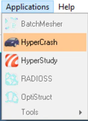
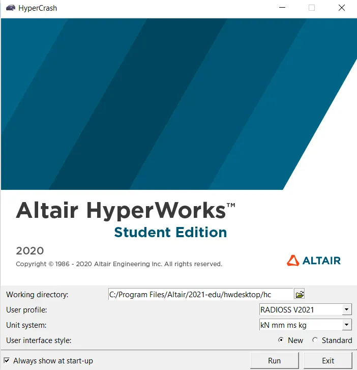
- Now go to Application> Hypercrash>>Select the unit system>>>Open
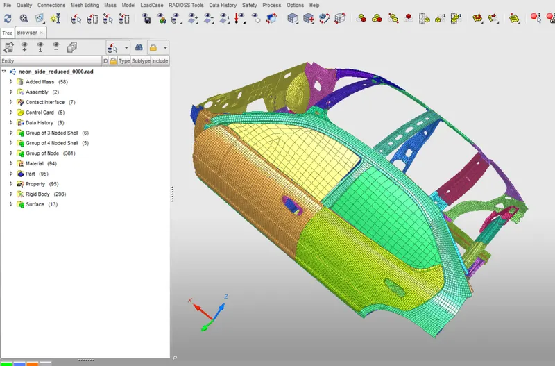
- Import the model in Hypercrash.
CHECK FOR PENETRATION AND INTERSECTION:-
- Penetration is defined as the overlap of the material thickness of shell elements. While intersection is defined as elements that actually pass completely through one another. All models and spesially impact model should be checked for penetrations and intersections to ensure the integrity of the model. Penetration adversely affect result and should be removed.
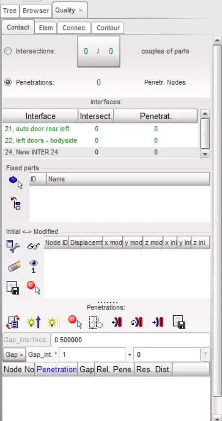
- Go to Qulaity>Check all solver contact interface>>
- As you can see in the below image there are no penetrations or intersections present in the model.
ADD MASS
- Mass balancing in order to maintain the CG of a car we have to add mass for the given components, in the given model here are so many parts are missing because of the node limits in the students version.
- To check the CG
- Go to Menu>Mass>>Blancing>>>Shoe CG point
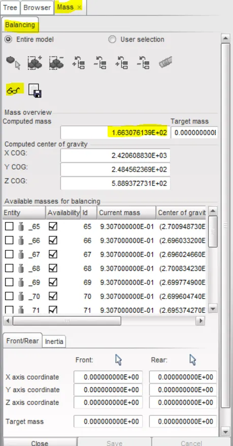
- Current Weight :- 166kg
- Target Weight:- 700 Kg
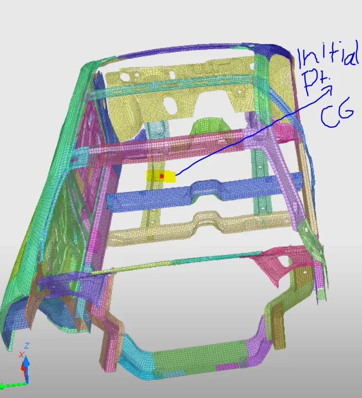
- In order to bring CG to our required position, the masses should be added to the nodes.
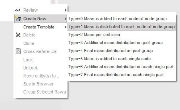
- For the adding masses Go to Load case>Added mass
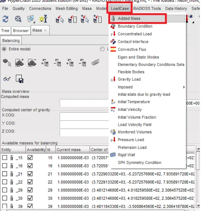
- In order to distribute the given mass to each node of the node group selected.
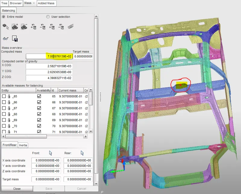
- After balancing the mass, we achieve our target mass that is 700kg as shown in the figure below and change CG posotion.
APPLYING INITIAL VELOCITY:-
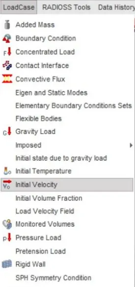
- To add initial velocity to the system in hypercrsah, we need to go to LoadCase>Initial Velocity.
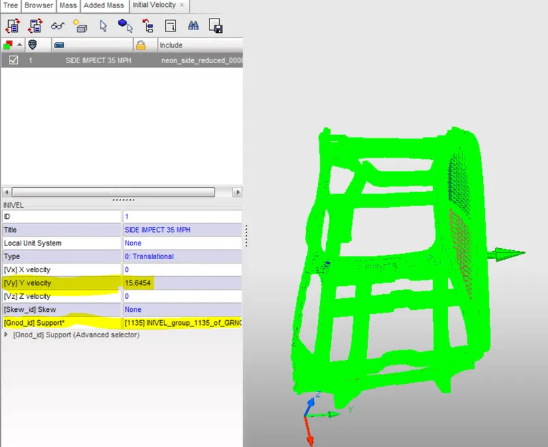
- Now export the radioss file from HyperCrash and import into the HyoerMesh to do rest of the case setup.
CREATE CONTACT INTERFACES:- Creating self contact.
CREATE RIGID WALL CYLINDER:-
- To create a cylindrical rigid wall at the left side of the car, we need the outermost node at the front door of the car. So we will create the outermost node on the element edge using temp nodes option.
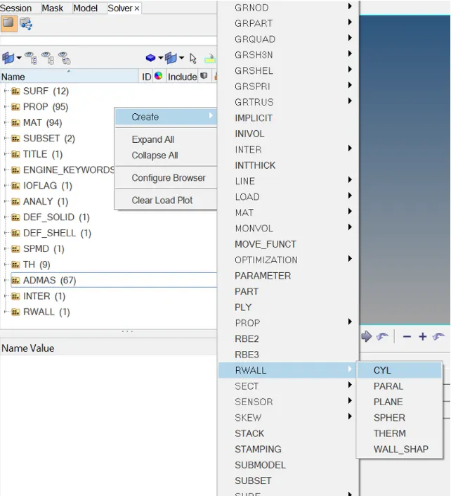
- To create cylindrical rigid wall.
- Go to Solver browser>Create>>Rwall>>>Cyl
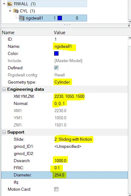
- Input required data to create cylindrical wall.
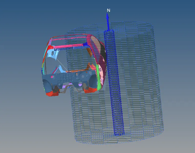
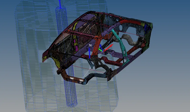
- The cylindrical rigid wall or the pole has been created as shown below image.
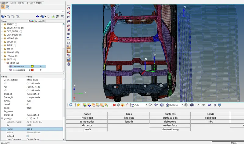
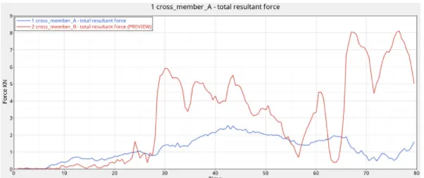
CREATING CROSS SECTION:-
Go to solver browser>Create>>sec>>>sect.
TO MEASURE INTRUSION:-
- In this section find the intrusion at B-pillar, hinge pillar and fuel tank. We need to create spring between left and right parts of the body, for creating spring go to 1D> SPRING2.
CREATE PROPERTY CARD FOR SPRINGS:-
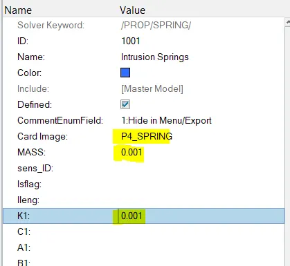
- After creating a property a new card will open there we have to select Crad Image as P4 SPRING and MASS 0.001 and SRTIFFNESS 0.001.
GO TO MODEL BROWSER>CREATE>>PROPERTY>>>RENAME AS INTRUSION SPRINGS
REQUESTING OUTPUT(TIME HISTORY FILES) FOR SPRINGS:-
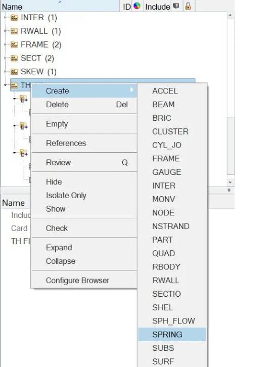
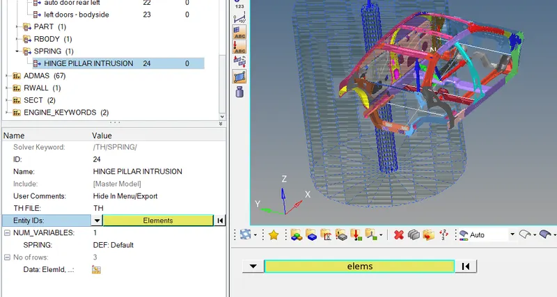
- In order to measure intrusion on the springs we have to request?TH?SPRING file.
- Go to solver browser>right click>>create>>>TH>>>SPRINGS
PEAK VELOCITY OF INNER NODE OF THE DOOR:-
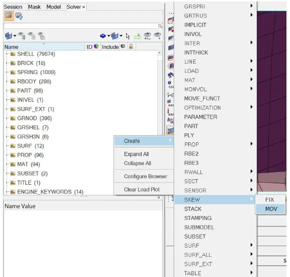
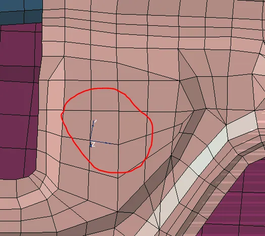
- To find peak velocity at the inner node of the door, we will create a moving frame at the node location by using right click on solver browser>create>>skew>>mov.
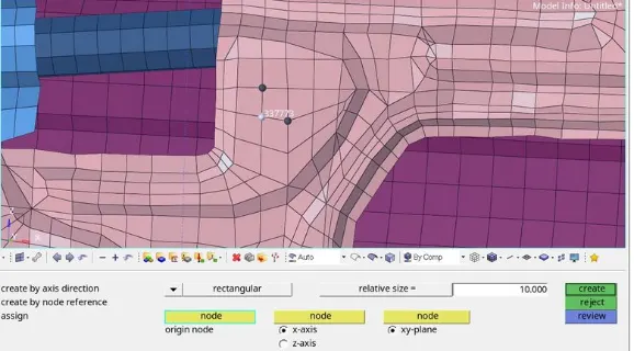
- Select the required node as origin node then select node to define x-axis and xy-plane.
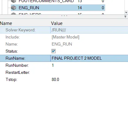
RUN THE SIMULATION:-
- Click on the analysis button.
- Save the model in the directory
- Type -nt 4 in option and click on Radioss.

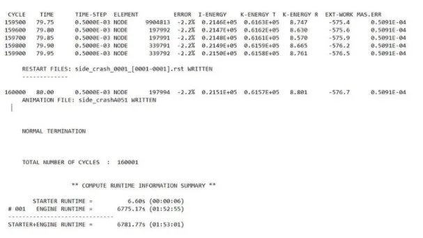
SIMULATION:-
- Displacement contour plot:-
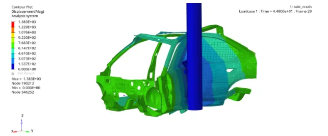
- In the above crash simulation of the vehicle we can see the cehicle body is impacting on a pole, after the impacting the frame of the vehicle deforms and the vehicle body gets contracted around the pole with left B-Pillar as the pivot point. The CG of the vehicle is in the same axis or direction of the pole, so we can see even deformation of the frame around the pole.
VON MISES STRESS:-
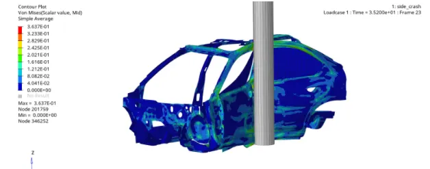
- The stress is more in B-Pillar and cross member as B-pillar takes the initial impact and then the impact is transfer to the cross member.
PLOT HYPERVIEW 2D:-
- The plots like energy differences, displacements velocity and the normal forces are analysed.
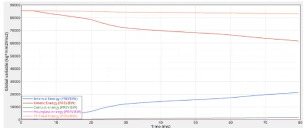
TOTAL ENERGY OF THE SYSTEM:-
- From the below plot, we can see that there is high amount of kinetic energy at the start of the simulation but as the simulation progresses, the kinetic energy in the vehicle decreases and gets converted into internal energy, so the internal energy increases in the same proportion. Thus the total energy in the system is almost constant at 85000 kg mm^2/ms^2 and due to some energy loss which we can see in energy error, there is some decrease in the total energy. We can also see some amount of contact energy in the model as we have defined the value of friction in Type 7 interface due to which contact energy is generated.
SECTIONAL FORCE ACTING IN CROSS MEMBERS:-
- From the below plot, we can see that the total resultant force in the rear cross member is more than the cross-member A, as the cross-member B is in line with the pole, it experience more force.
INTRUSIONS:-
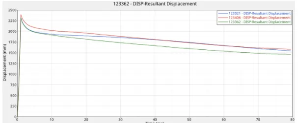
BLUE LINE - INTRUSION NODE AT HINGE PILLAR
RED LINE - INTRUSION NODE AT B-PILLAR
GREEN LINE - INTRUSION NODE AT FUEL TANK
- INTRUSION NODE AT HINGE PILLAR- The final displacement at hinge pillar region is 1542.62 mm and the initial distance of fuel tank from of reference is 1310.62 so total intrusion is 1310.62-1542.62=-232.00 mm. Thus the total intrusion at hinge pillar region is 232mm mm but the minus sign indicates that the intrusion is increased after the crash.
- INTRUSION NODE AT B-PILLAR- The final displacement of node at B-pillar is 1577.81 mm and the initial distance of fuel tank from frame of reference is 1319.49 so total intrusion 1319.49-1577.81=-258.32mm. Thus the total intrusion at B-pillar region is 258.32mm but the minus sign indicates that the intrusion is increased after the crash.
- INTRUSION NODE AT FUEL TANK- The final displacement of fuel tank region is 1462.31mm and the initial distance of fuel tank from frame of reference is 1319.97. So total intrusion is 1319.97-1462.31=-142.34. Thus the total intrusion at fuel tank region is 142.34mm but the minus sign indicates that the intrusion is increased after the crash.
PEAK VELOCITY OF INNER NODE OF DOOR:-
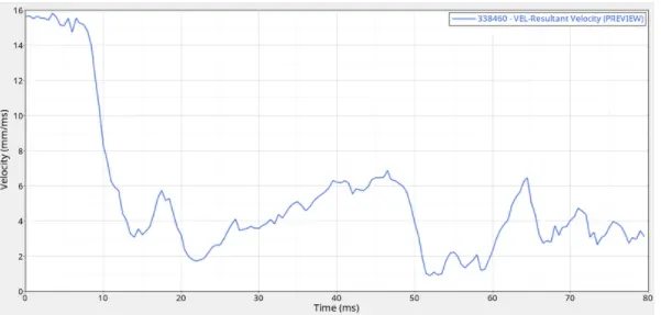
- The above plots helps to understand,with the actual inner side of the door moves in the direction of the driver during the pole impact. The peak velocity measure at the inner door point is 15.84mm/ms till 8ms, after that the speed is starting to reduce to a great extent.
CONCLUSION-
- Thus the model was simulated for a side crash and the results were discussed from the output file energy error and mass error is in an acceptable range so i can conclude that the simulation is pretty stable. Cross members A and B are plying important role in the impact force absorption. So improving the cross-member material or adding some extra support element near the cross member can improve their performance, also for the fuel tank side as we discuss earlier need some reinforcement. We can also work on the B-pillar property improvement as it is the closest part which is comes in the contact wih the force during the side crash.