SIDE CRASH OF NEON BiW MODEL USING HYPERMESH AND RADIOSS
Side Pole
Some side impacts involve a vehicle travelling sideways into rigid roadside objects such as trees or poles. Often this is the result of a loss of control on the part of the driver, owing to speeding, misjudgement of a corner or because of a skid in slippery conditions. Such accidents are severe and the frequency of death or serious injury is high.
In Euro NCAP’s test, a car is propelled sideways at 32 km/h against a rigid, narrow pole. The car is placed at right angles to the direction of motion, or as is done from 2015 onwards, at a small angle away from the perpendicular. Where a vehicle is equipped with a centre airbag to protect against the front seat occupants hitting each other, two average male side impact dummies are placed in the front seats. Where there is no centre airbag, single dummy is placed on the driver’s seat.
This is a very severe test of a car’s ability to protect the driver’s head. As the loading on the car is so localised, deformation can be very high and the pole can penetrate deeply into the passenger compartment. Without effective protection, the pole would strike the head resulting in serious injuries. Head protection airbags – often curtain airbags mounted above the side windows but sometimes seat-mounted thorax/head airbags – have become a common solution but great care is needed to ensure effective performance of such devices.
OBJECTIVE
To perform side crash of the given model in hypermesh and radioss with below request
Input requests:
- Check unit system and either follow [Mg mm s] or [Kg mm ms].
- Create appropriate interface ,friction 0.2 and recommended parameters.
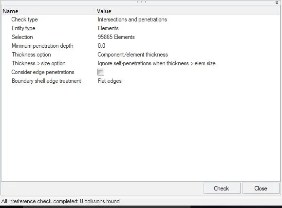
- Make sure of no penetration and intersections.
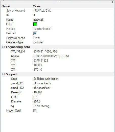
- Create rigid wall with friction 0.1 as per referance model.
- Compare the model weight with the referance model and use added masses to reach target weight 700kg while getting CG about the required range.
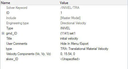
- Initial velocity as shown in picture.
- Use model checker to ensure good quality.
- Timestep :0.5 to 0.1 microseconds.
- Run 80ms.
Output requests:
- Sectional force in the cross member.
- Intrusion at B pillar,hinge pillar and fuel tank region.Provide recommendation on what can help to reduce Fuel tank intrusion.
- Peak velocity of inner node of the door.
BIW-MODEL
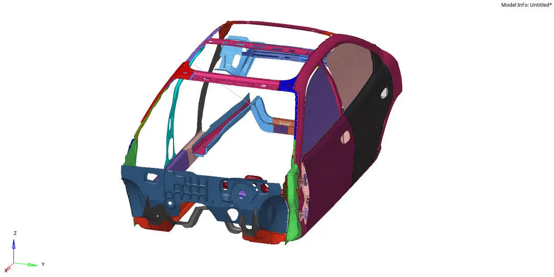
MODEL SETUP
INPUT REQUESTs
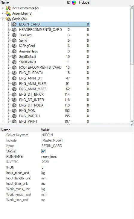
- first the given neon_side_reduced_0000.rad file is imported in radioss and unit system is set to [Kg,mm,ms] from Model--cards--begincards
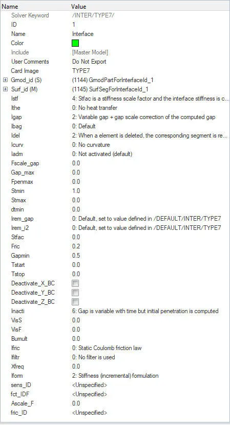
- Then type7 (Edge to surface) interface is created with recommended properties and with friction coefficient of 0.2
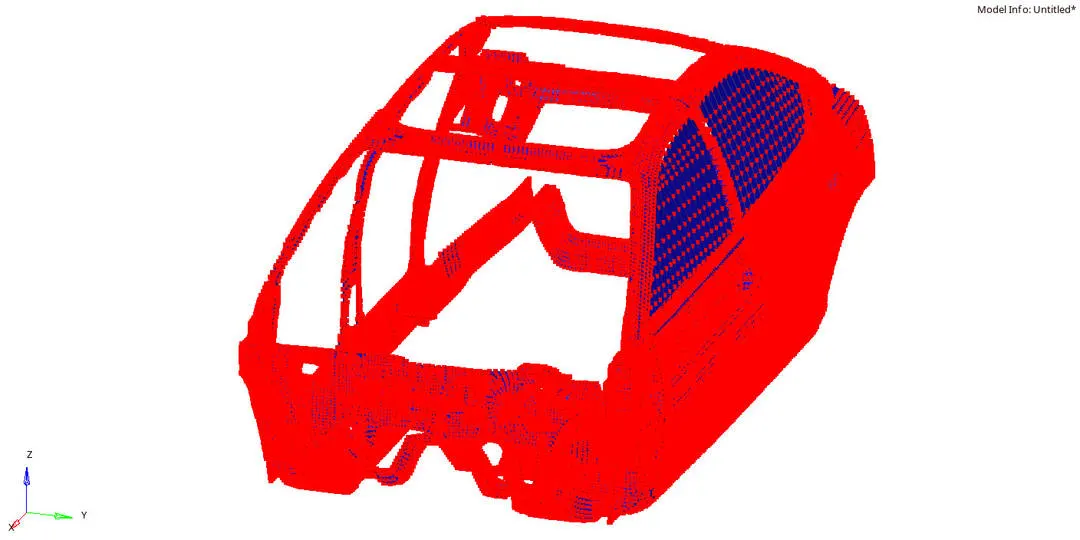
- Slave and mass nodes aare defined as in the below image
- Check for Penetrations and interference in hypermesh by Tools--penetration check
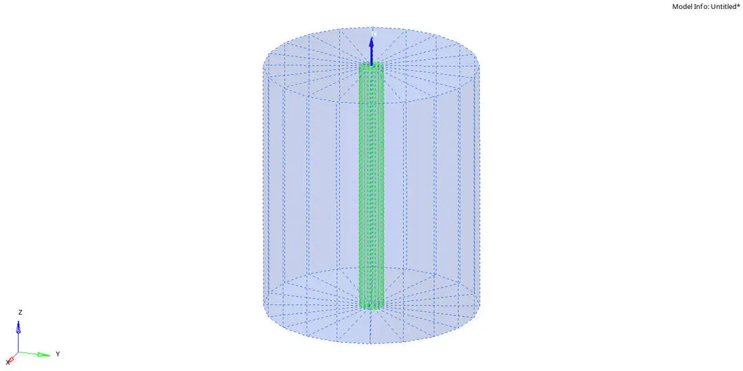
- infinte Rigid pole is created in hypermesh by BCS--create--Rigid wall for crash @ `90^o`
- For crash @ `90^o` initial Velocity of 15.54mm/ms is applied to the components at Global Y through Tools--create cards--Boundary conditions--INVEL/TRA and the Ground ID is selected as shown below
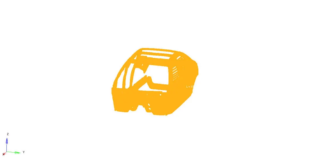
- infinte Rigid pole is created in hypermesh by BCS--create--Rigid wall for crash @ `75^o`
- The given model is rotated along the global Z @ `15^o`
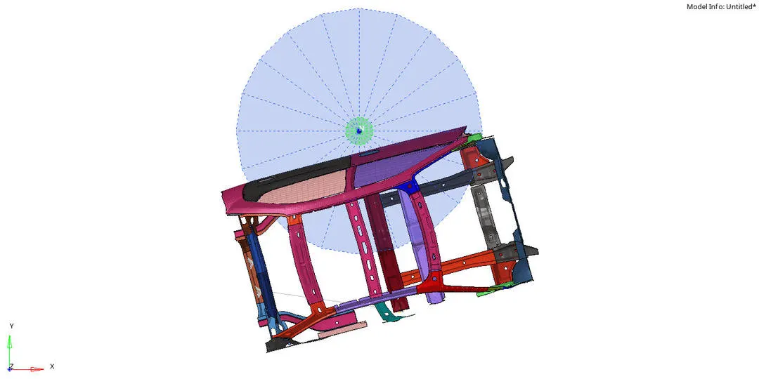
- For crash @ `75^o` initial Velocity of 8.89mm/ms is applied to the components at local skew Y through Tools--create cards--Boundary conditions--INVEL/TRA and the Ground ID is selected as shown below
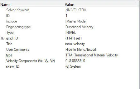
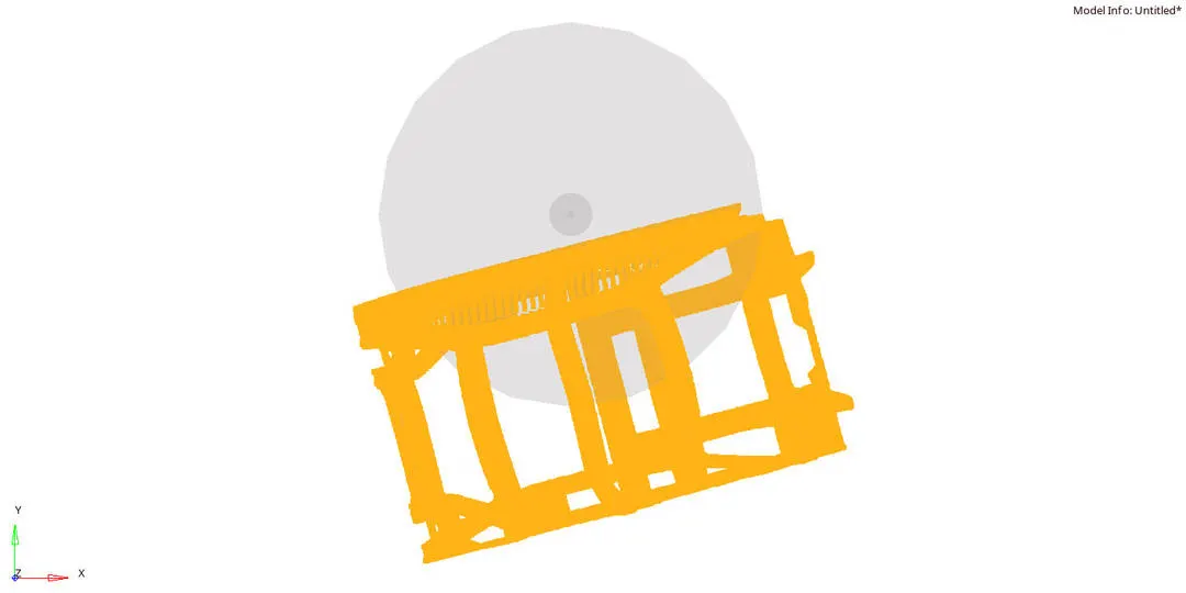
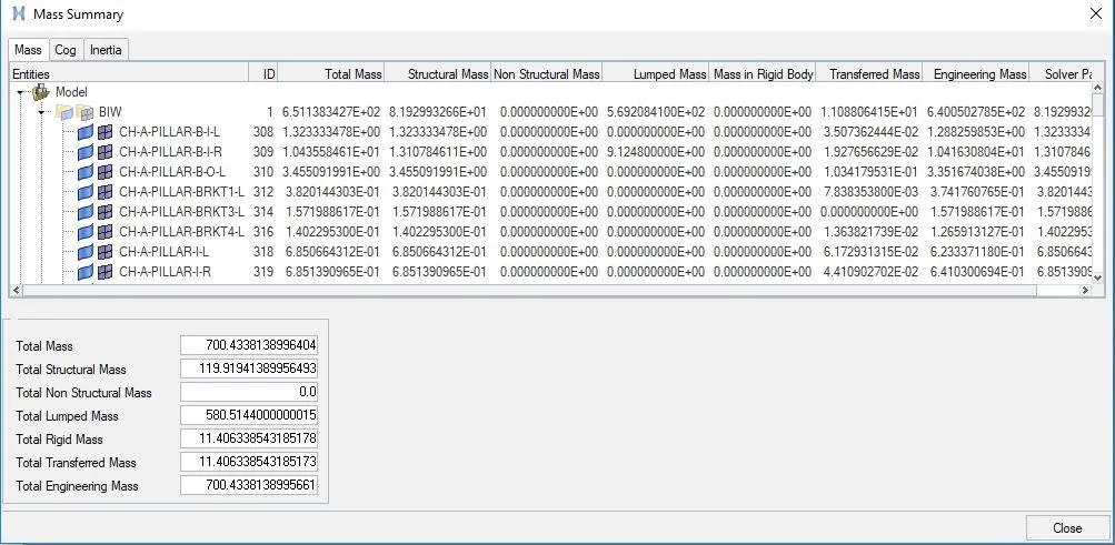
- Then the mass of 700kg is added based on the required COG
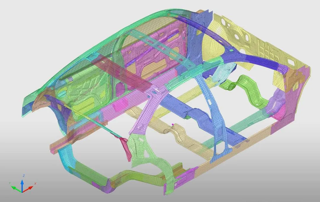
- Quality of the model is checked in hypermesh by (tools--modelchecker--radiossblock) and the errors were rectified .
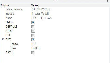
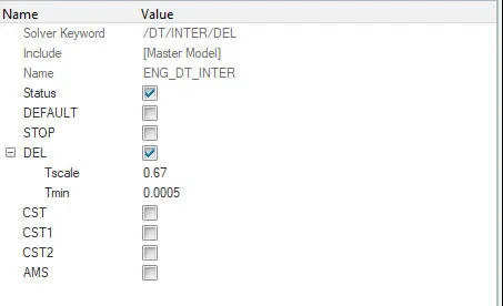
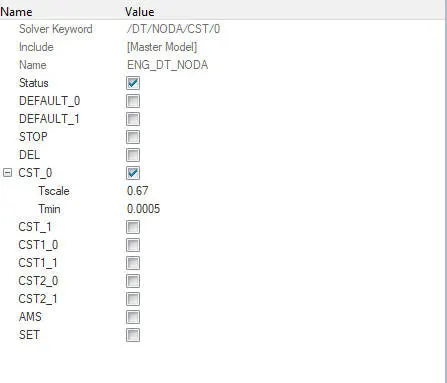
- Here the crictial time step must be maintained within 0.1ms to 0.5ms
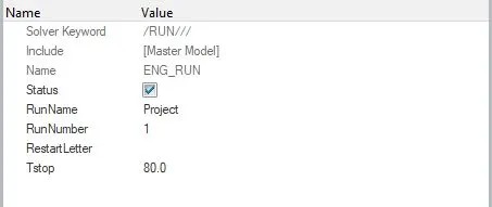
- The Tstop is set to 80ms in engine run card (Tools--createcards--Run)
OUTPUT REQUESTS
- CROSSECTIONAL FORCES
- MID RAIL & SEAT REINFORCEMENT
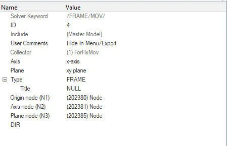
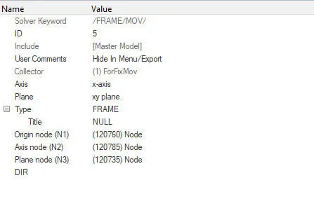
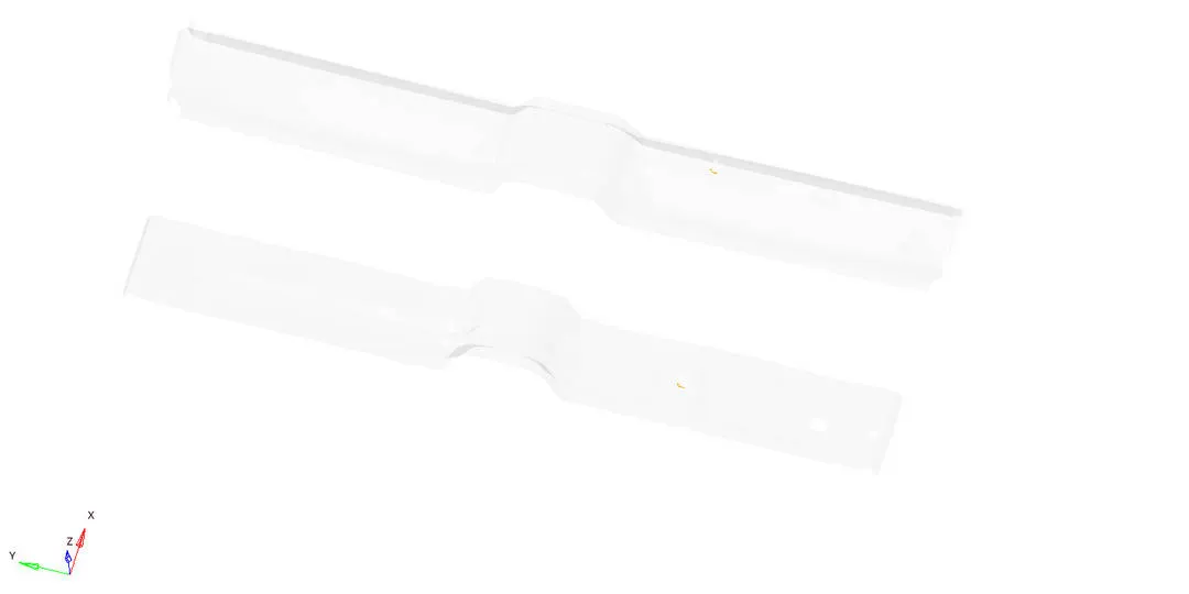
FRAME(TOOLS--createcards--frame--mov)
The origin is selected at the node then xaxis and xy plane is defined with respective nodes as shown below
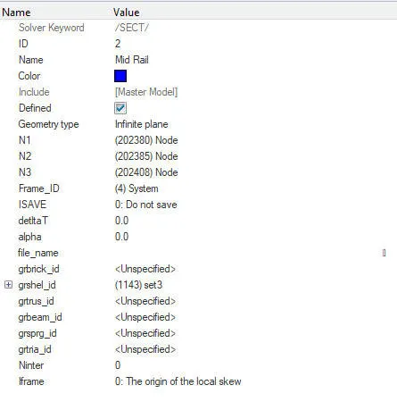
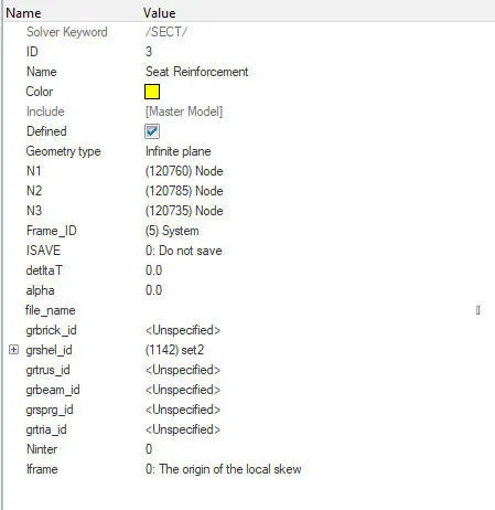
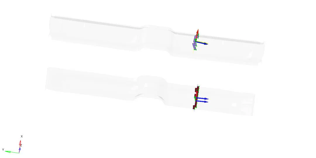
SECTION(TOOLS--createcards--SEC)
In section card the frame id and elements were selected in the respective elements are created.
Intrusions
DISPLACEMENT
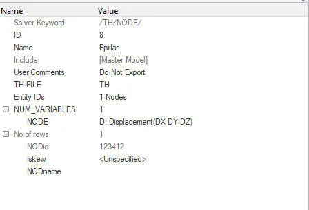
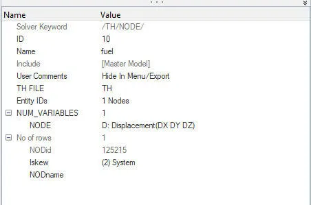
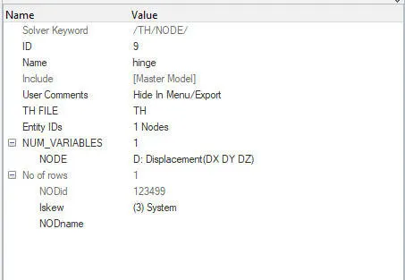
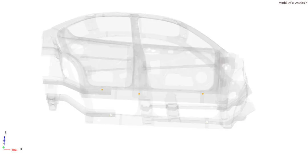
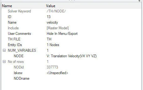
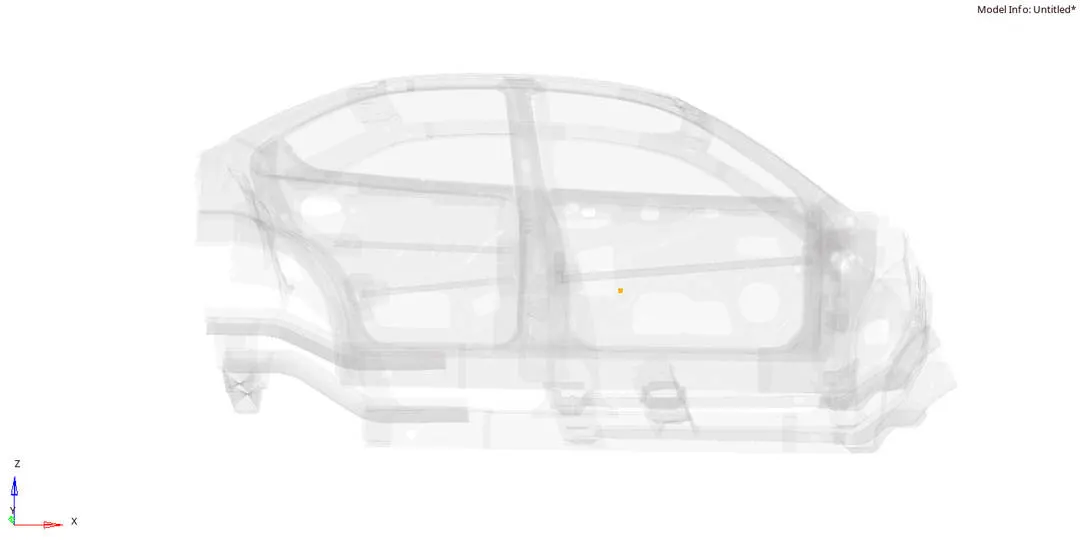
The intrusion on the near Fuel tank, bpillar and hinge can be known by creating /TH/Node from the (Tools--create cards--TH--NODE) with respective node id
VELOCITY AT INNER DOOR PANEL
The velocity on the inner door panel can be known by creating /TH/Node from the (Tools--create cards--TH--NODE) with respective node id
UNIT SYSTEM

ENERGY ERROR & MASS ERROR
The Energy error is about -1.8% with acceptable and mass error is abot 0.000047 which is due to the nodal time step

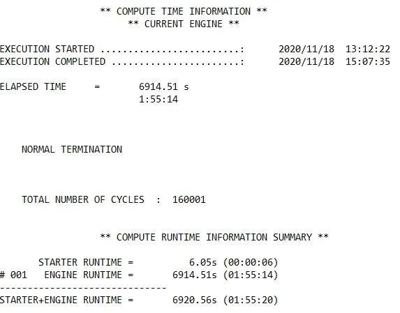
TOTAL SIMULATION TIME
RESULTS
ANIMATION
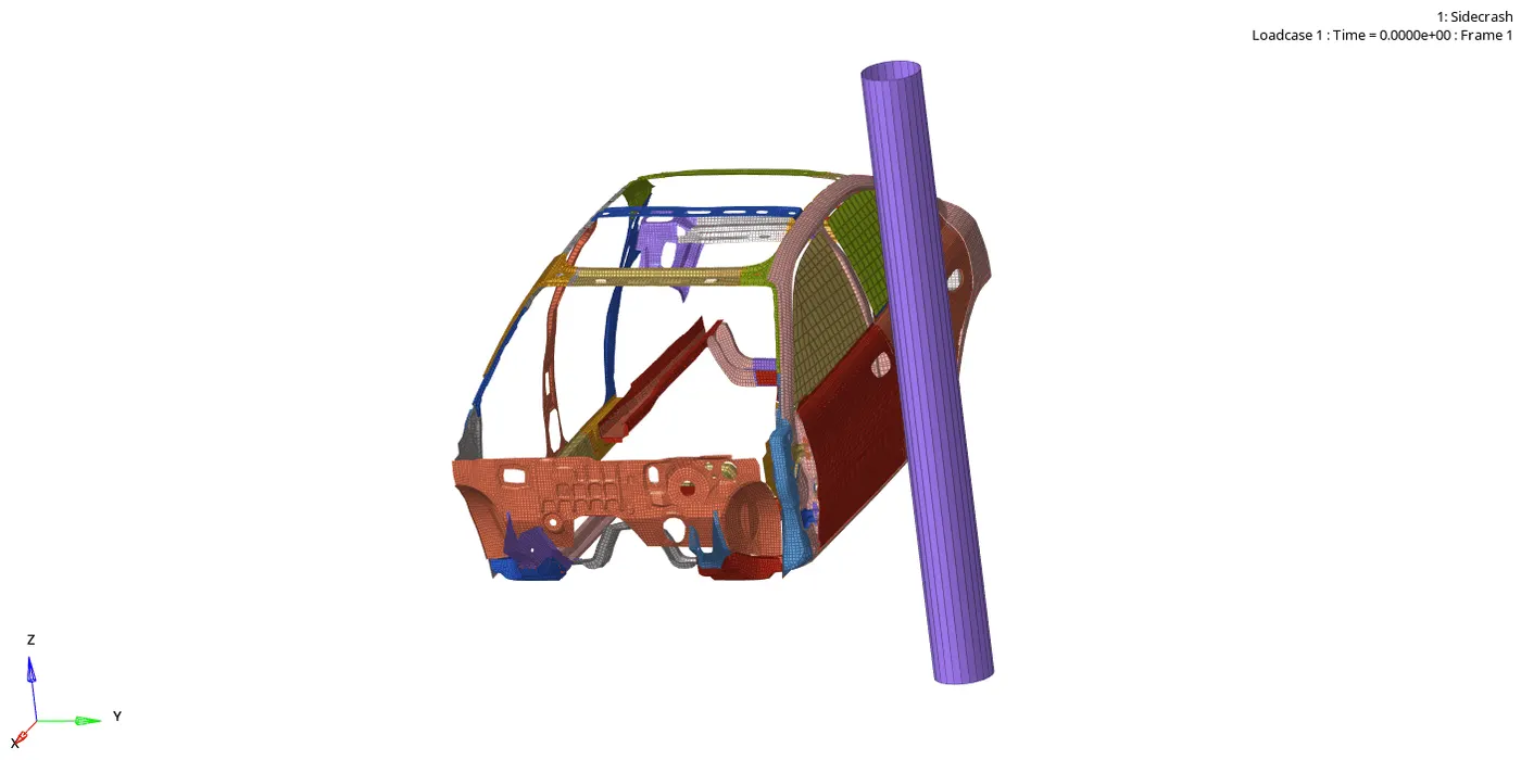
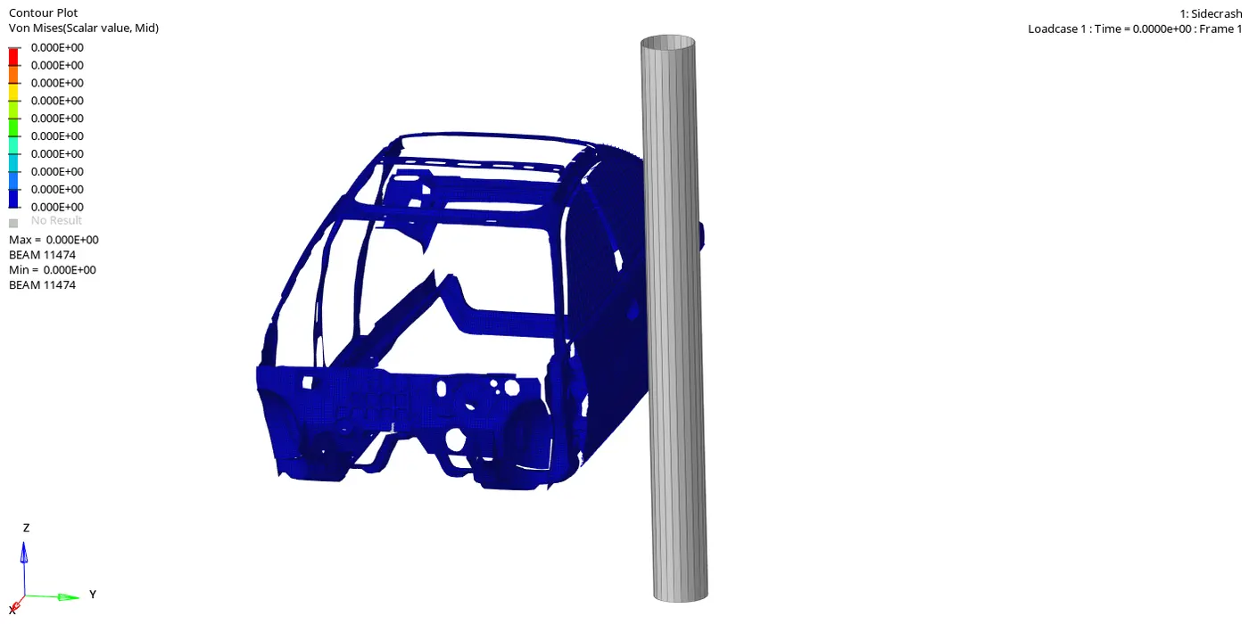
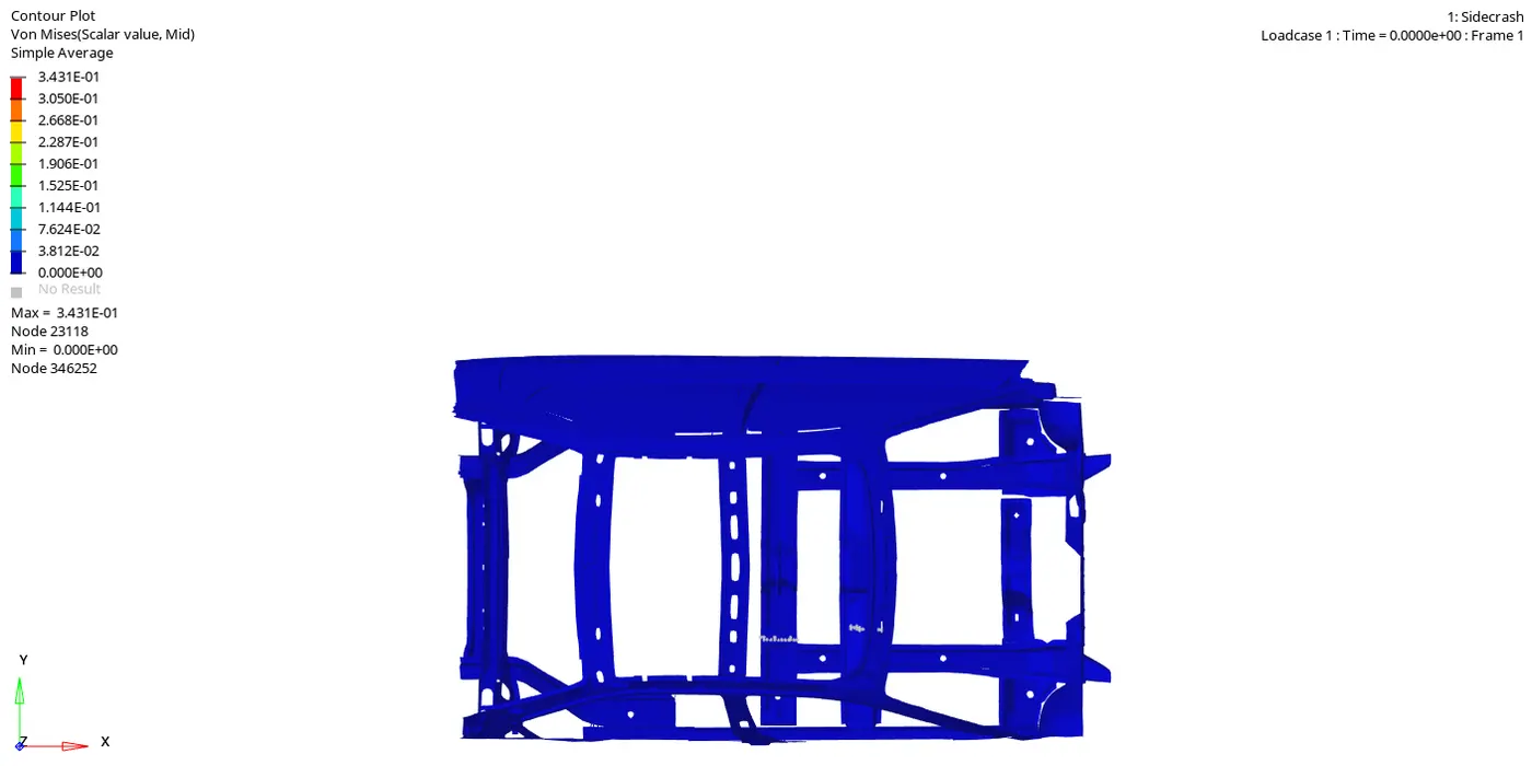
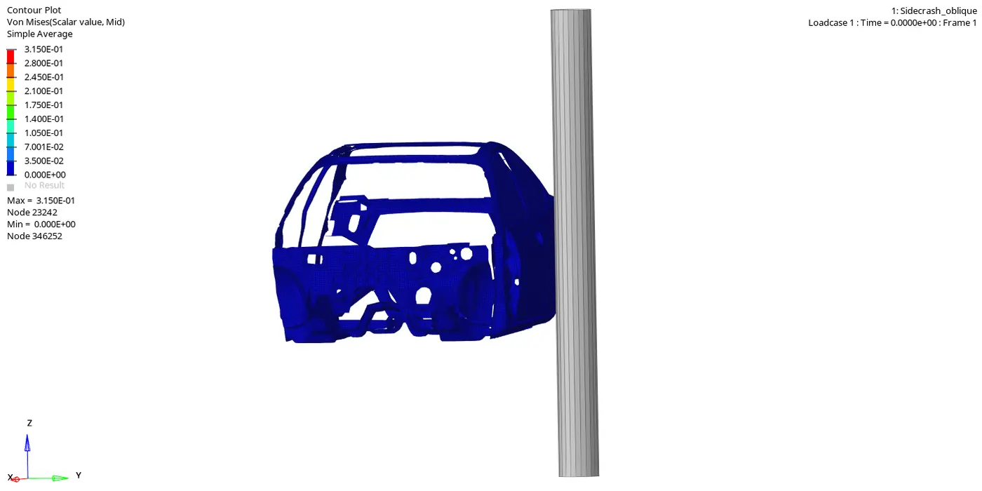
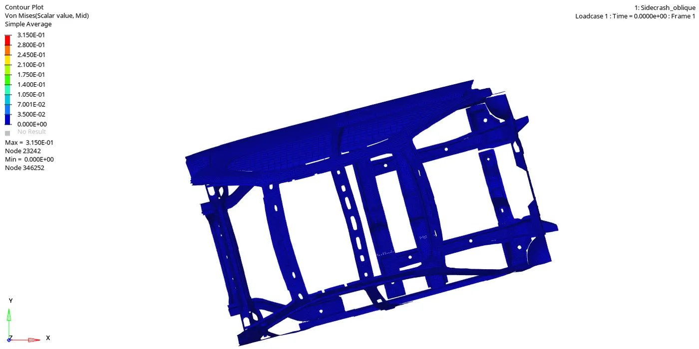
- VON MISES STRESS
Von Mises stress is a value used to determine if a given material will yield or fracture. It is mostly used for ductile materials, such as metals. The von Mises yield criterion states that if the von Mises stress of a material under load is equal or greater than the yield limit of the same material under simple tension then the material will yield.
At `90^o`
At `75^o`
DISPLACEMENT
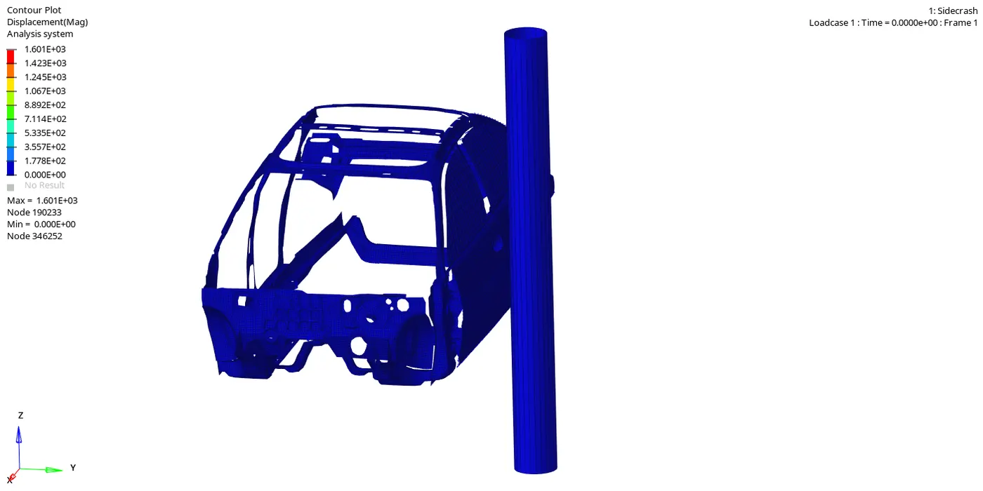
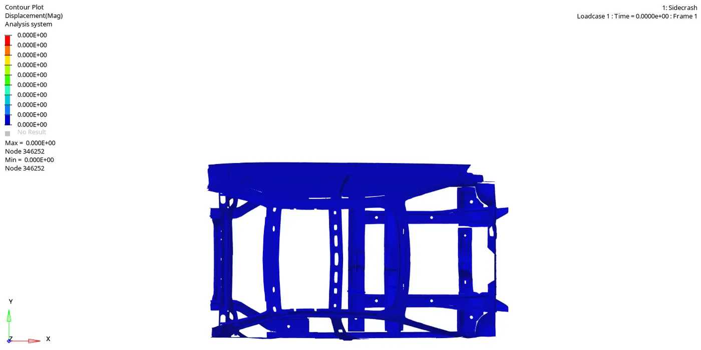
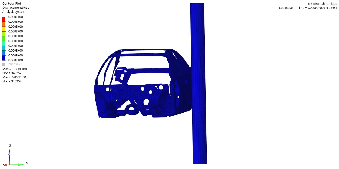
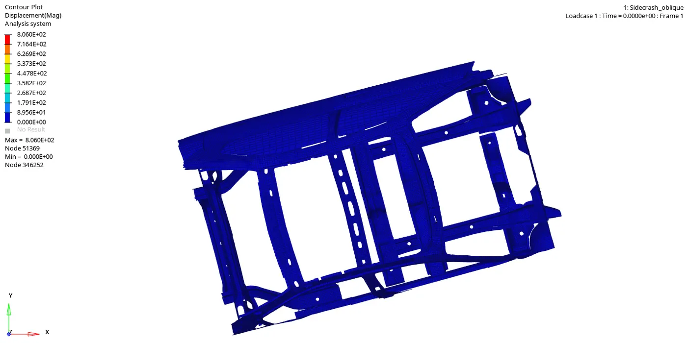
From this contour we can see the displacement of the elements once after the crash occurs and the displacemenet. maximum displacement of 1601mm is obsereved at the node 190233 .
At `90^o`
At `75^o`
PLOTS
- ENERGY
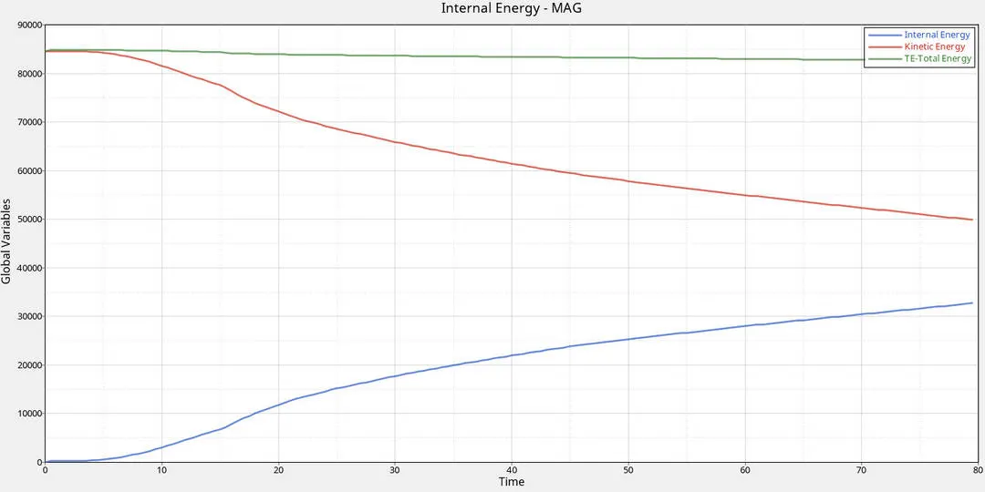
At `90^o`
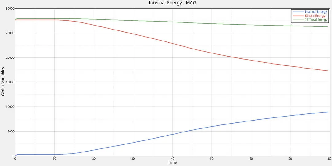
from the plot we can see that kinetic energy starts with maximum value and decreases gradually throughout the simumilation due to the crash whereas the internal energy of the components increases with respect to the time which is actually the mirror of the Kinetic energy
At `75^o`
- CONTACT ENERGY
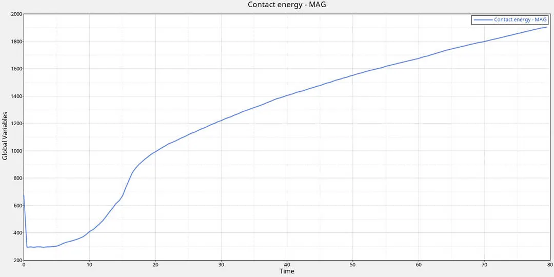
At `90^o`
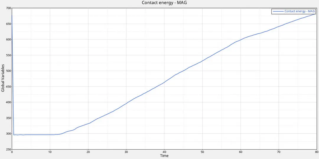
We can see the drop in contact energy at the (0-0.2ms) due to the self contact once it hits the pole the contact energy increases gradually throughout the simulation.
At `75^o`
- VELOCITY
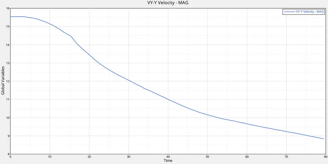
Here at the start of the simulation the velocity is at 15.54mm/ms and reduces gradually throughout the simulation with respective time
At `75^o`
- INTRUSIONS
HINGE
At `90^o`
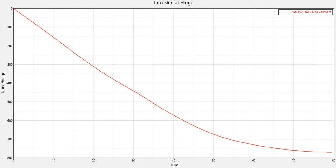
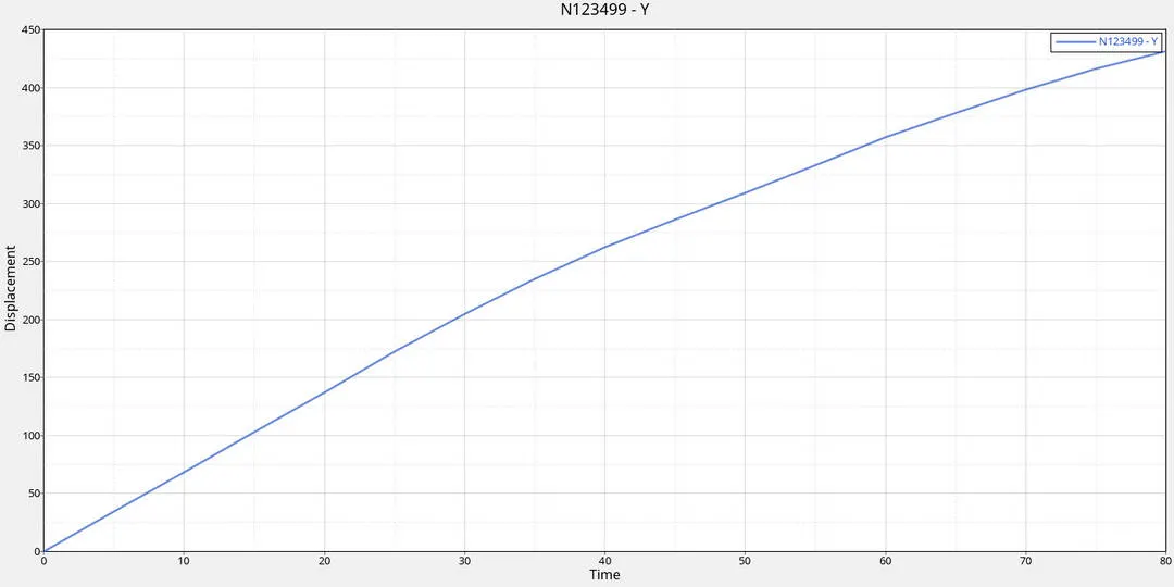
from the plot we can observe the displacement of the node is negative direction of the local skew(Z) which is about 760mm
At `75^o`
B-PILLAR
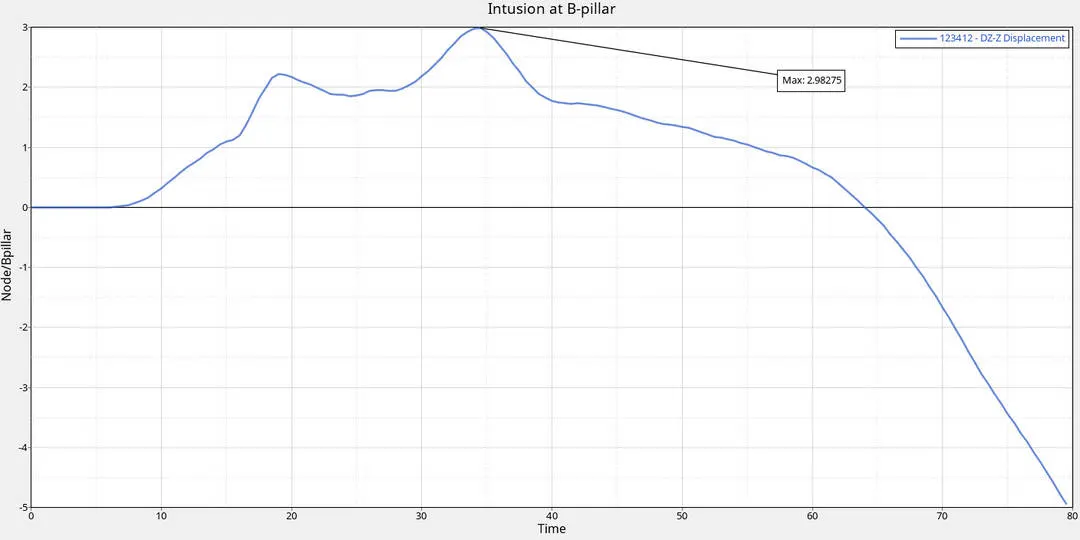
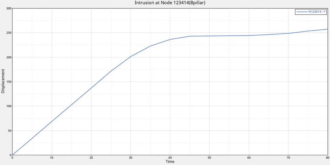
from the plot we can observe the displacement of the node is direction of the local skew (Z) which is about 2.982mm which is low due to the position of the rigid pole .
At `75^o`
FUEL TANK
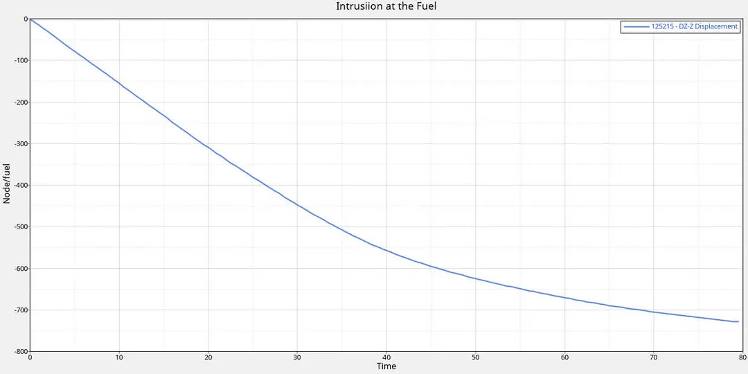
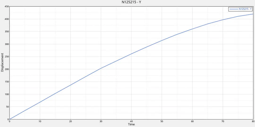
from the plot we can observe the displacement of the node is negative direction of the local skew which is about 720mm. In trusion near the fuel tank is high it can be reduced by increasing the stiffness of the fuel tank rail component
At `75^o`
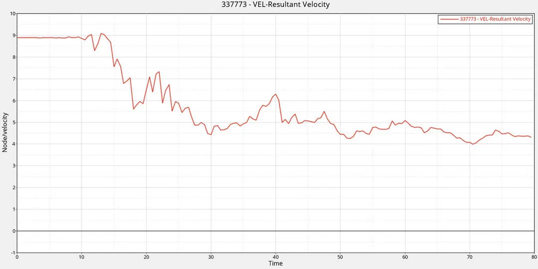
PEAK VELOCITY
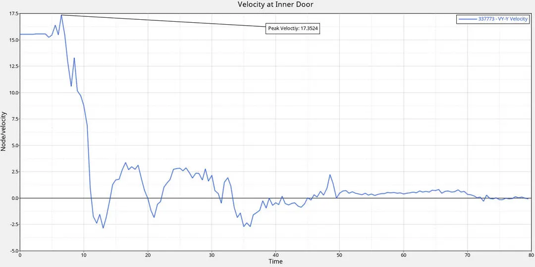
Here the velocity peaks higher than the initial velocity since the placement of the node is slightly offset to the B pillar at the instance of the crash the node experiences a bit higher than the initial velocity and drops .
At `75^o`
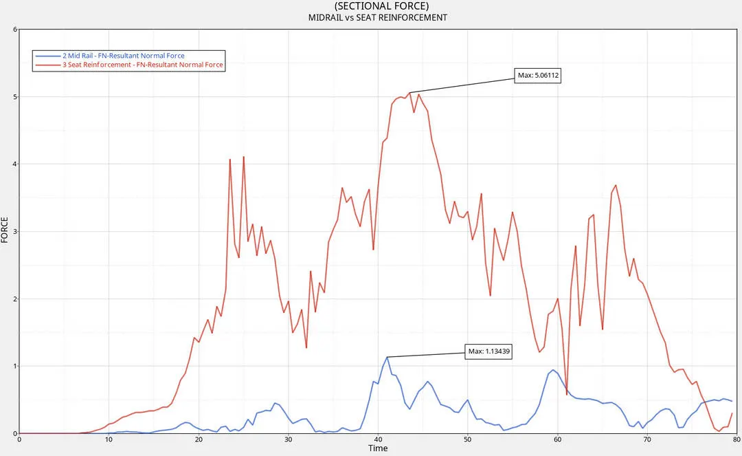
CROSSECTIONAL FORCE
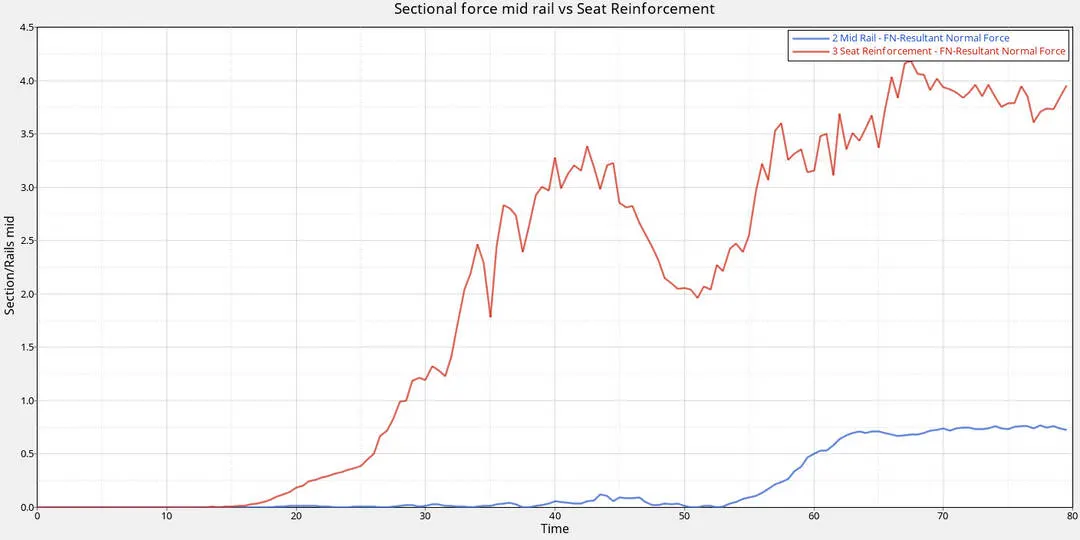
The force on the mid rail is low than the seat reinforcement because of the placement of the the rigid pole which perpendicuolar to the seat reinforcement
At `75^o`
CONCLUSION
From this project i was able to the setup the given model with requested inputs and outputs .
crash @ `90^o`
- Peak Velocity @ inner door panel - 17.3524 mm/ms
- Intrusion @ hinge - 775mm
- Intrusion @ Fuel tank - 725mm
- Intrusion @ B Pillar - 5mm
- Sectional forces @ Seat Reinforcement-5.06112KN/mm^2
- Sectional forces @ Mid Rail - 1.13439KN/mm^2
crash @ `75^o`
- Peak Velocity @ inner door panel - 9.12 mm/ms
- Intrusion @ hinge - 448mm
- Intrusion @ Fuel tank - 442mm
- Intrusion @ B Pillar - 254mm
- Sectional forces @ Seat Reinforcement-4.25112KN/mm^2
- Sectional forces @ Mid Rail - 0.60439KN/mm^2