Simulation of Side Crash of a car using Hypermesh with Radioss
AIM: To Analyze the Side Crash (BIW) of a Car by simulating with recommended parameters.
KEYWORDS: A-pillar, B-pillar, Rigid Wall, Rigid Body, Section, Skew, Frame, etc.,
SOFTWARE: Hypermesh - Hypercrash
OBJECTIVE:
- Check the given Car BIW for any free parts are presented.
- Check for the Penetration & Intersection.
- Create a Rigid wall (Cylinder) with the friction of 0.1.
- Add mass to locate proper COG.
- Make the vehicle dynamic with an initial velocity of 30 kmph as per the standard.
- Use model checker to ensure good quality.
- Create a Timestep (0.5 - 1 microsecond) and run time (80 ms).
- Run the simulation and plot the required results.
INTRODUCTION:
The past few decades have seen an increasing application of CAE for simulation of crash phenomena particularly due to the development of high computing machines and parallel computing techniques. The increase in safety standards can be attributed to the improvement of structural crashworthiness performance through Finite Element Analysis.
The effect of crashes and impacts on structures is one problem and the second one which is of prime importance is the safety of occupants. We find that occupant safety simulation offers reasonably accurate results today which can save a lot of testing time and overall design cycle time. Today’s dummies have closer dynamic properties and also include the correct load-carrying capacity to allow interaction with the structure as compared to earlier dummy models which didn’t take into account loads entering into the body. The CAE development for this application was delayed due to the unavailability of high-end computing power and it can be said that such simulations are barely 20 years old. Although there has been a tremendous increase in the application of software to solve problems related to the automotive industry, aerospace industry, and drop test of components, still the best is yet to come and research has been very active in all aspects of this application ranging from basic physical phenomena understanding to development of efficient numerical algorithms and finally the development of a general-purpose software which can solve almost all kinds of problems. We now find the simulation of tests prescribed by the ECE and FMVSS standards and regulations quite a common application. Other simulations widely used are the bird strike impact analysis and jet engine blade containment analysis about FAR in the aerospace industry. The main aim of this chapter is to introduce the basics of structural crashworthiness simulations in terms of the solution methodology and discuss some of the practical simulations performed in the industry
I. Importance of Crash-worthiness:
The automotive industry has probably the widest application of crash simulation. Simulating the crash-worthiness of the vehicle in terms of very simple models based on the spring-mass damper systems was the focus when the computers were very slow. Nowadays software such as RADIOSS and others have very wide practical aspects such as the use of special seat belt elements and the development of dummies for occupant safety. Several standards have originated in various countries and it is impossible to give a detailed account of these. In the following, we discuss some of the most essential applications related to the automotive industry. There are very detailed procedures such as five-star ratings and no attempt will be made here to take a detailed account of these.
All that we do is just determine the evolution of the basic quantities such as displacement, velocity, and acceleration given initial conditions on displacement and velocity concerning time. All other quantities that can be derived from these and most important are the element stresses, plastic strains, contact forces, and the energies such as kinetic, potential energy, and overall energy absorption characteristics popularly called energy management. Most software would commonly implicitly solve the dynamic equilibrium equation but the most popular way that should be used for highly non-linear problems is to use explicit time integration schemes such as a central difference scheme. There are several advantages of such a procedure and the most important is that it leads to an algorithm that can be easily program-med, does not require any matrix inversion procedure, and further is extremely suitable for a fast parallel computing Methodology.
II. Standards Maintained to conduct the test:
The most common standards in the USA are FMVSS (Federal Motor Vehicle Safety Standards) regulations and ECE ( Economic Commission of Europe ) regulations in Europe. In India, ARAI testing standards are used now.
FMVSS standards can be obtained free of cost from the website and there are three 3 series listed in the Vol 49 Code of Federal Regulations. The 100 series deals with active safety or crash avoidance and the 200 series forms the most important aspects of crashworthiness tests. Listed in series 200 are several standards and an attempt has been made to give the reader a brief survey of them. One can refer to the information available online on NCAP (New car assessment program), IIHS (Insurance Institute for
Highway Safety) and NHTSA (National Highway Traffic safety association).
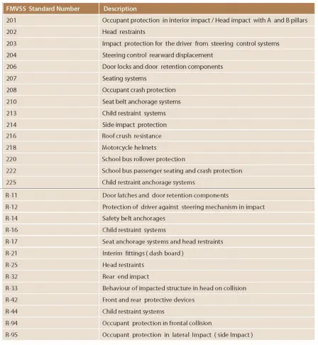
Figure 1: FMVSS Standard
IIHS evaluates a vehicle's crashworthiness with the help of six tests: moderate overlap front, driver-side small overlap front, passenger-side small overlap front, side, roof strength, and head restraints & seats. For front crash prevention ratings, the Institute conducts low- and moderate-speed track tests of vehicles with automatic braking systems. IIHS also conducts evaluations of headlight systems and of the child seat attachment hardware known as LATCH. The descriptions below explain how each test is conducted and how the results translate into ratings.
For the crash tests we conduct, we purchase the vehicles from dealers just like an ordinary consumer. If the test is being conducted at the manufacturer's request and isn't part of our regular testing schedule, then the manufacturer reimburses us for the vehicle.
A frontal crash is the most common type of crash resulting in fatalities. Major strides have been made in frontal protection, thanks in large part to the crash test program that the National Highway Traffic Safety Administration (NHTSA) began in the late 1970s and the crashworthiness evaluations that IIHS began in 1995.
IIHS conducts three different frontal crash tests: a moderate overlap test (formerly known as the frontal offset test), a driver-side small overlap test, and a passenger-side small overlap test.
III. Body in white (BIW) is the stage in automobile manufacturing in which a car body's frame has been joined together, that is before painting and before the motor, chassis sub-assemblies, or trim (glass, door locks/handles, seats, upholstery, electronics, etc.) have been integrated into the structure. Assembly involves different techniques such as welding (spot, MIG/MAG), riveting, clinching, bonding, and laser brazing.
• Body in white is an assembly of a frame and panels
• Homogeneous Materials - steel or aluminum sheets or composites
• The name derives from manufacturing practices before steel unibody monocoques — when automobile bodies were made by outside firms on a separate chassis with an engine, suspension, and fenders attached.
IV. Side Impact Test Details:
- A small-size adult female in the driver seat
- The dummy is secured with a seat belt
- The vehicle, angled at 75 degrees, is pulled sideways at 20 mph into a 25cm diameter pole at the driver’s seating location
- Evaluation of injury to the head, chest, lower spine, abdomen, pelvis.
- For side pole ratings, it is possible to compare all vehicles with each other
The IIHS began conducting the side impact test in 2003. In this test, the test vehicle remains stationary while a four-wheeled sled, with a deformable barrier attached, strikes the side of the vehicle at 31 mph (50 km/h). This test is used to simulate the impact of a high-riding pickup or SUV on the subject vehicle.
In 2019, the IIHS began modifying the test by using a heavier sled, changing the barrier design, and increasing the impact speed from 31 to 37 mph (60 km/h). The IIHS cited the current test being unrealistic as the main reason for the modification. The modified test has yet to be officially conducted.
Since our side crash program was launched, NHTSA has made changes to its New Car Assessment Program. It continues to conduct its original side crash test representing a T-bone crash and using a moving barrier. In 2010, NHTSA added a side pole test to address side crashes in which vehicles slide into fixed objects. Unlike NHTSA's moving-barrier test, the pole test requires protection for the driver's head. Both NHTSA tests evaluate vehicle performance solely on measures from the dummies' sensors.
The IIHS side test typically causes more damage than either of the NHTSA tests. We directly evaluate structural deformation in addition to the measures from dummy sensors. We also review the test video to check that structures and airbags work well together to protect occupants.
In the NHTSA moving barrier crash test, the barrier, which resembles the front of a car from the 1970s, strikes the side of the test vehicle at 39 mph and an angle of 27 degrees. Although the test speed is higher than the IIHS test, the lower barrier shape pushes against the strong lower portion of the door frame that is often missed in real crashes. This makes it easier for a vehicle's structure to protect occupants than in the Institute’s test, in which the SUV-like barrier misses that structure except in the case of taller vehicles.
In NHTSA's pole test, the test vehicle slides sideways at 20 mph and a 75-degree angle into a 10-inch-diameter rigid pole. A SID-IIs dummy is in the driver seat, but the rear-seat head protection is not tested. In contrast, our single, moving-barrier test encourages good head protection for both fronts- and rear-seat occupants.
V. PROCEDURE:
Initially, the model was to be imported to Hypermesh or Hypercrash. Here Hypercrash is used to modify the parameters and to check the model for Free parts, penetration, and Intersection. Here, 3 free parts are identified which is connected with rigid body. After checked the model for penetration, a Rigid Pole is created with friction 0.1, and the diameter of a pole is 254 mm. The distance is maintained between car and pole is 150mm. The rigid pole should be perpendicular to the model in order to get the proper impact of BIW of a car with a search distance of 900. The model is tested for Side impact with a certain velocity of 30 Kmph. There are some mass is added to locate the proper Center of Gravity and also to reach the target weight of a Car by comparing the full car model. The Lumped mass is 581.87 kg which is assigned for front seats and suspension supports. Before running the simulation check for quality if any issue means need to resolve so that proper result can be obtained if not the simulation will fail. The engine run time is set to 80ms and time_step is followed as 0.5 microseconds. The time step (dt) for Brick, Noda & Inter is 0.1, 0.5 & 0.5 microseconds respectively. The model consists of 95 parts which are connected with a rigid body and assigned with some mass value. The contact interface used is Type7 with recommended properties. To get the impact on a particular part, Sections are created along with the frame and added to the output block. Sections are created in Cross-members. To get the compression distance Intrusion (TH/Node) is created. For getting the value of Intrusion nodes, Springs are created with recommended properties.
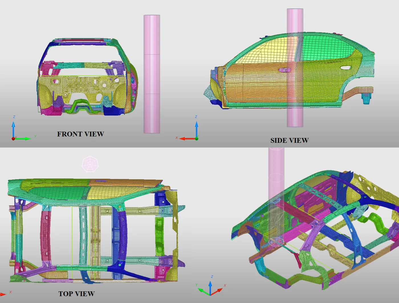
Figure 2: Car BIW for Side Impact
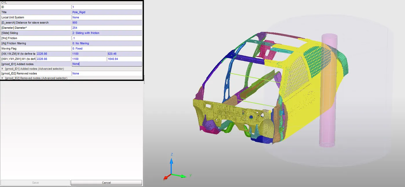
Figure 3: Rigid Pole
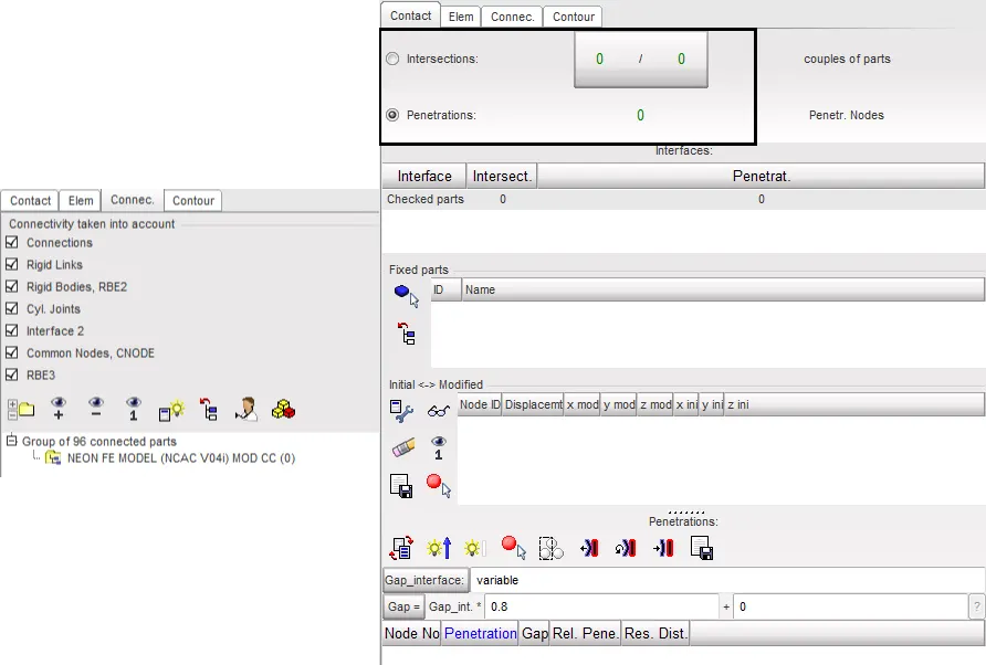
Figure 4: Free Parts & Penetration check
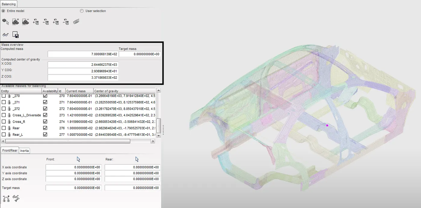
Figure 5: Location of COG
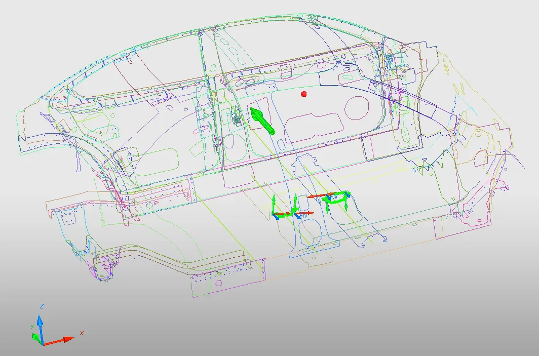
Figure 6: Invel, Section, Spring & Peak velocity of inner node at Door
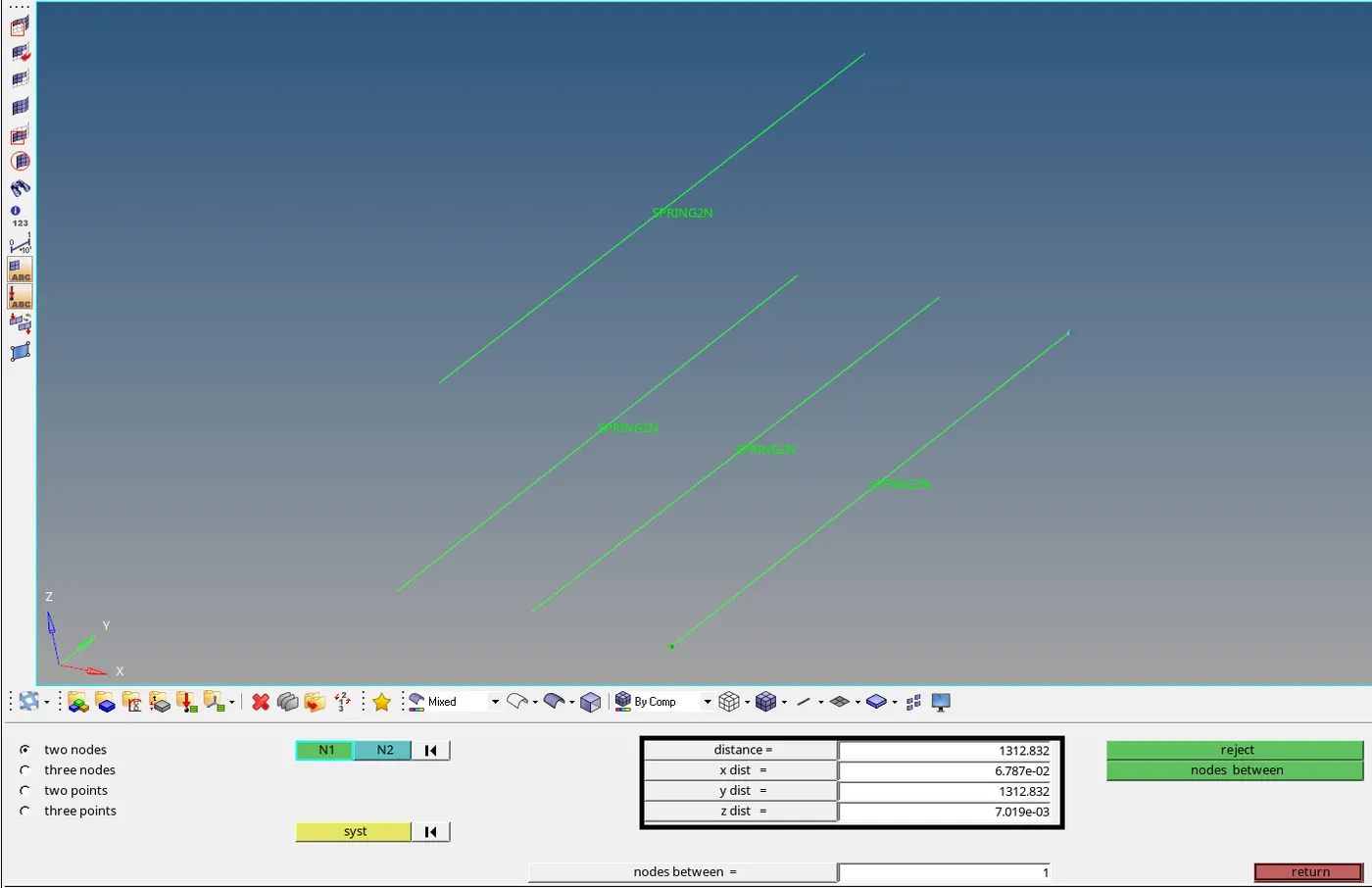
Figure 7: Spring Actual Distance
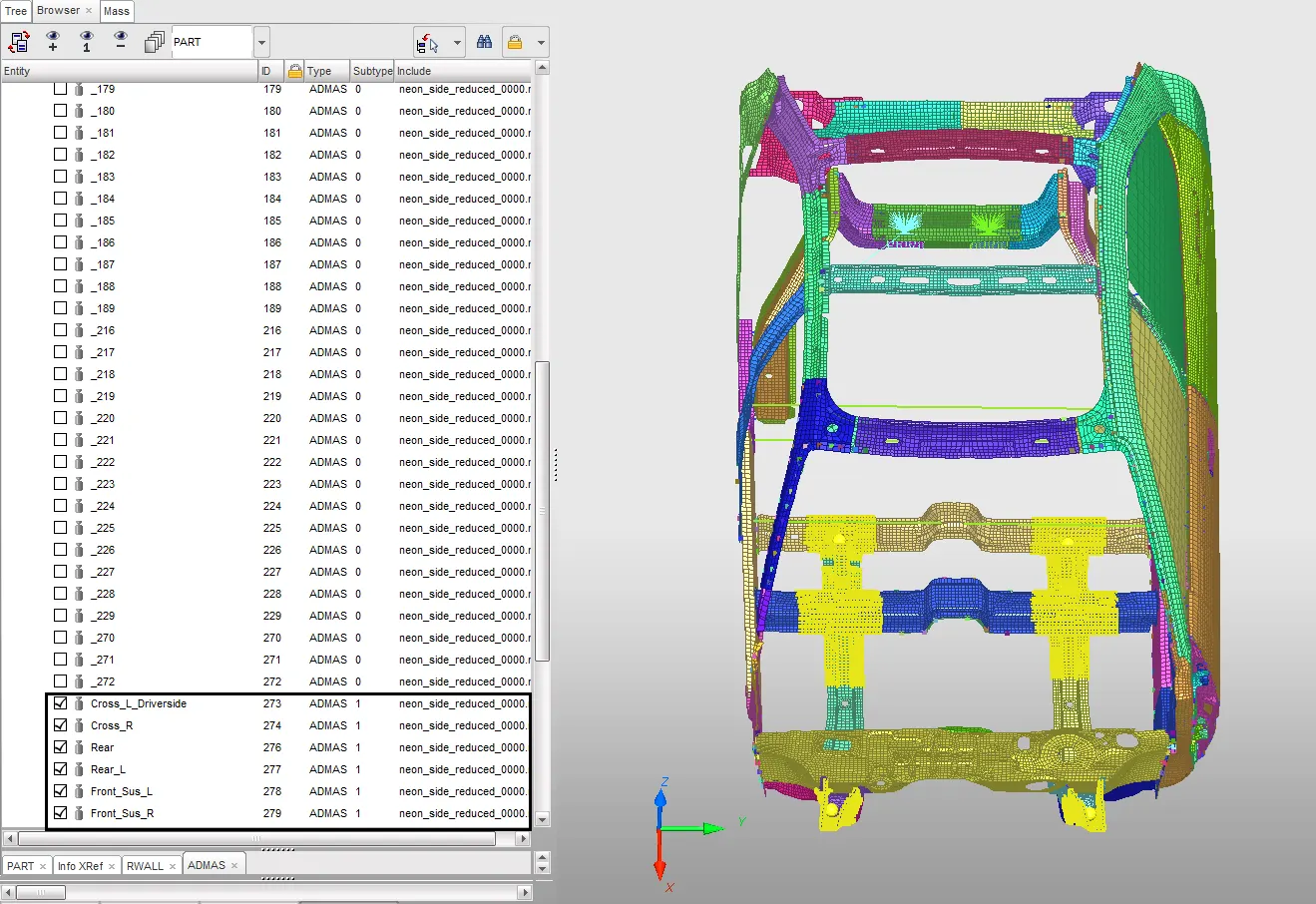
Figure 8: Added Mass to locate COG
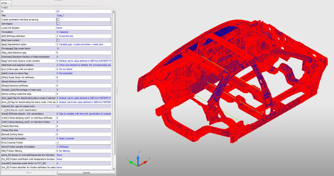
Figure 9: Type 7 Contact Interface with Recommended Properties
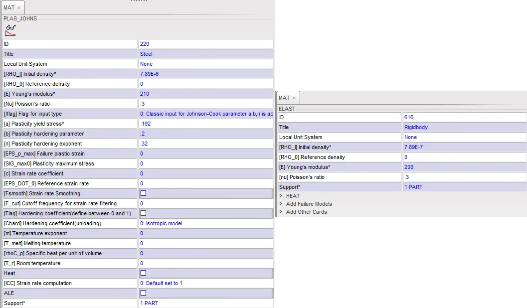
Figure 10: Law 1 & Law 2 Material properties
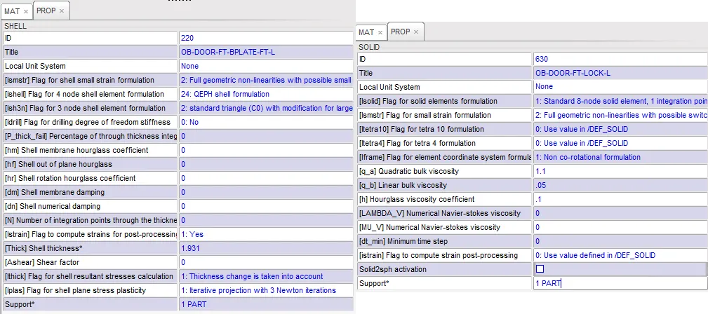
Figure 11: Properties of Shell & Solid
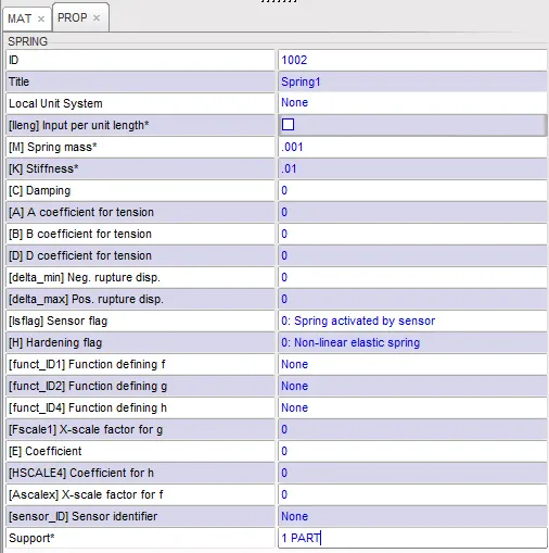
Figure 12: Properties of Spring
RESULTS:
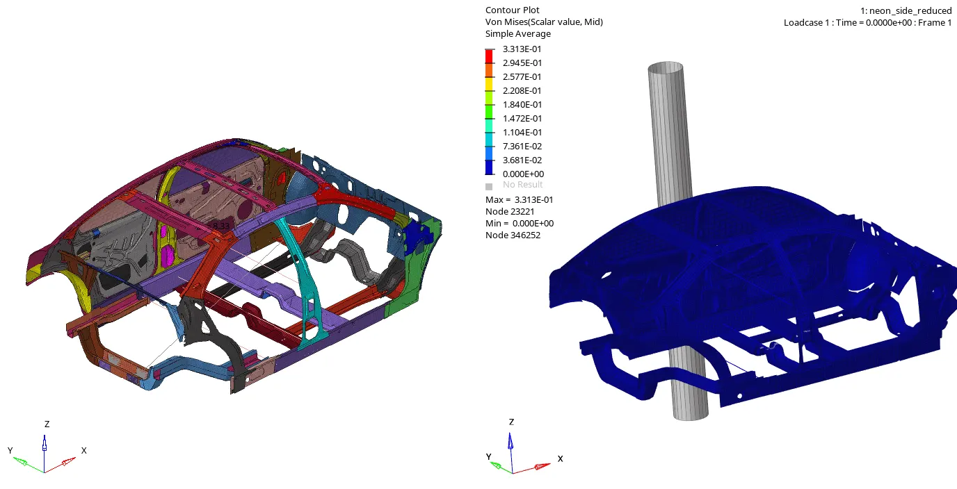
Figure 13: Animation of Side Impact
The car is moving at a velocity of 30 kmph which hits the Rigid Pole, due to this impact some of the parts are largely deformed and shown the animation. The maximum stress is developed as 0.331 N/mm2 in 80 millisecond.
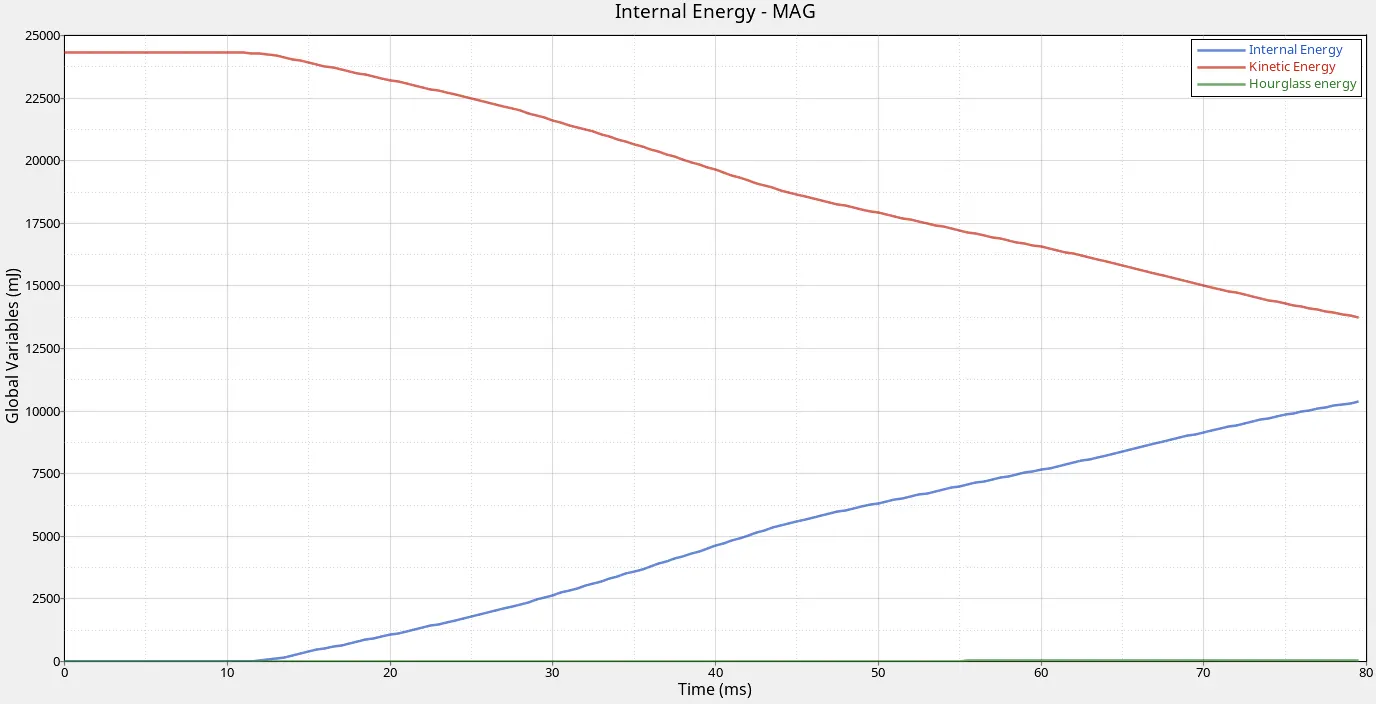
Figure 14: Energy Variation and Utilization
The Kinetic & Internal Energy is constant for 13 ms because the object is not get in contact with rigid pole. After 13 ms, the Kinetic energy is decreasing from 24304 to 12500 due to Side impact parallely the internal energy is increasing 0 to 11000.
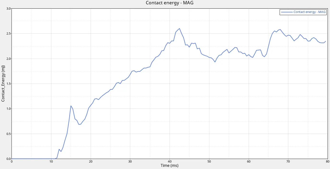
Figure 15: Contact Energy Variation
When objects collide, contact forces transfer energy so as to change the objects' motions. When two objects interact, each one exerts a force on the other, and these forces can transfer energy between them. Fields contain energy that depends on the arrangement of the objects in the field. The max energy formed as 2.7 mJ.
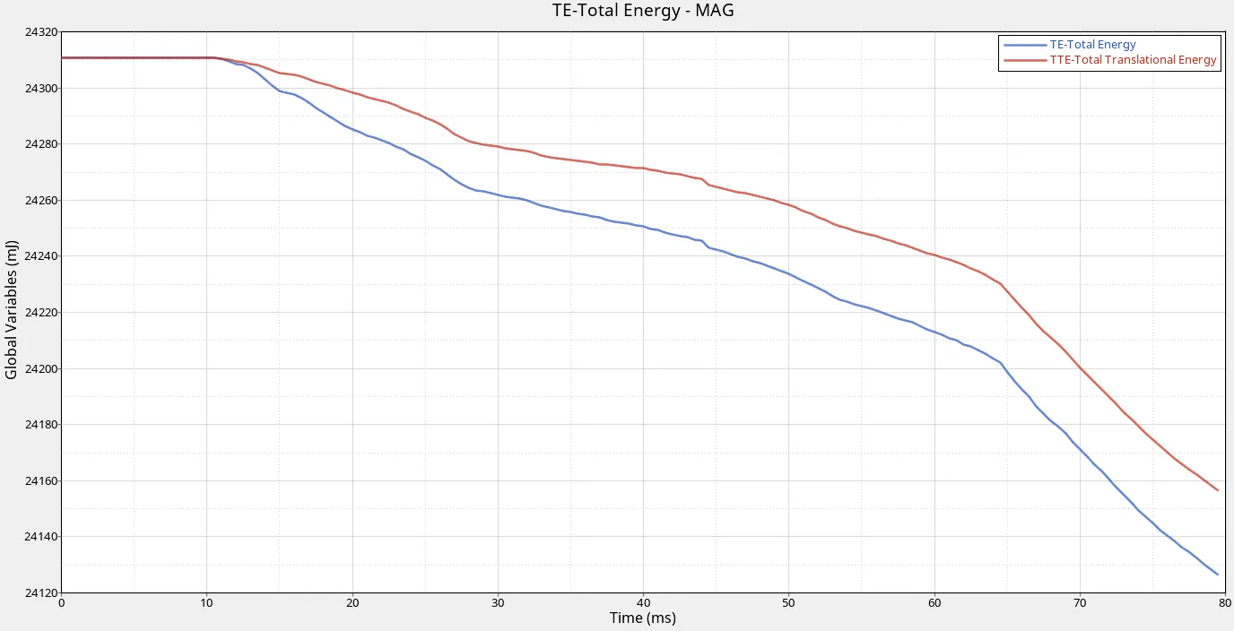
Figure 16: Total Energy utilisation
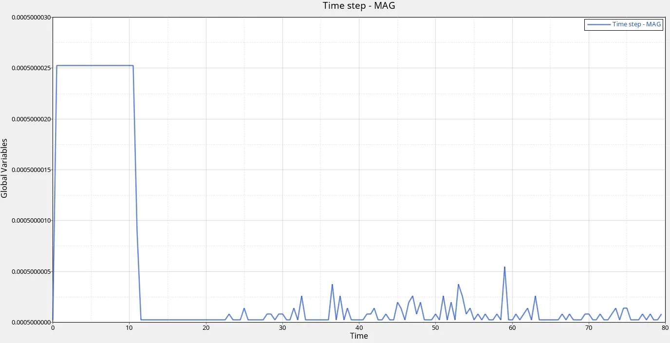
Figure 17: Time step variation
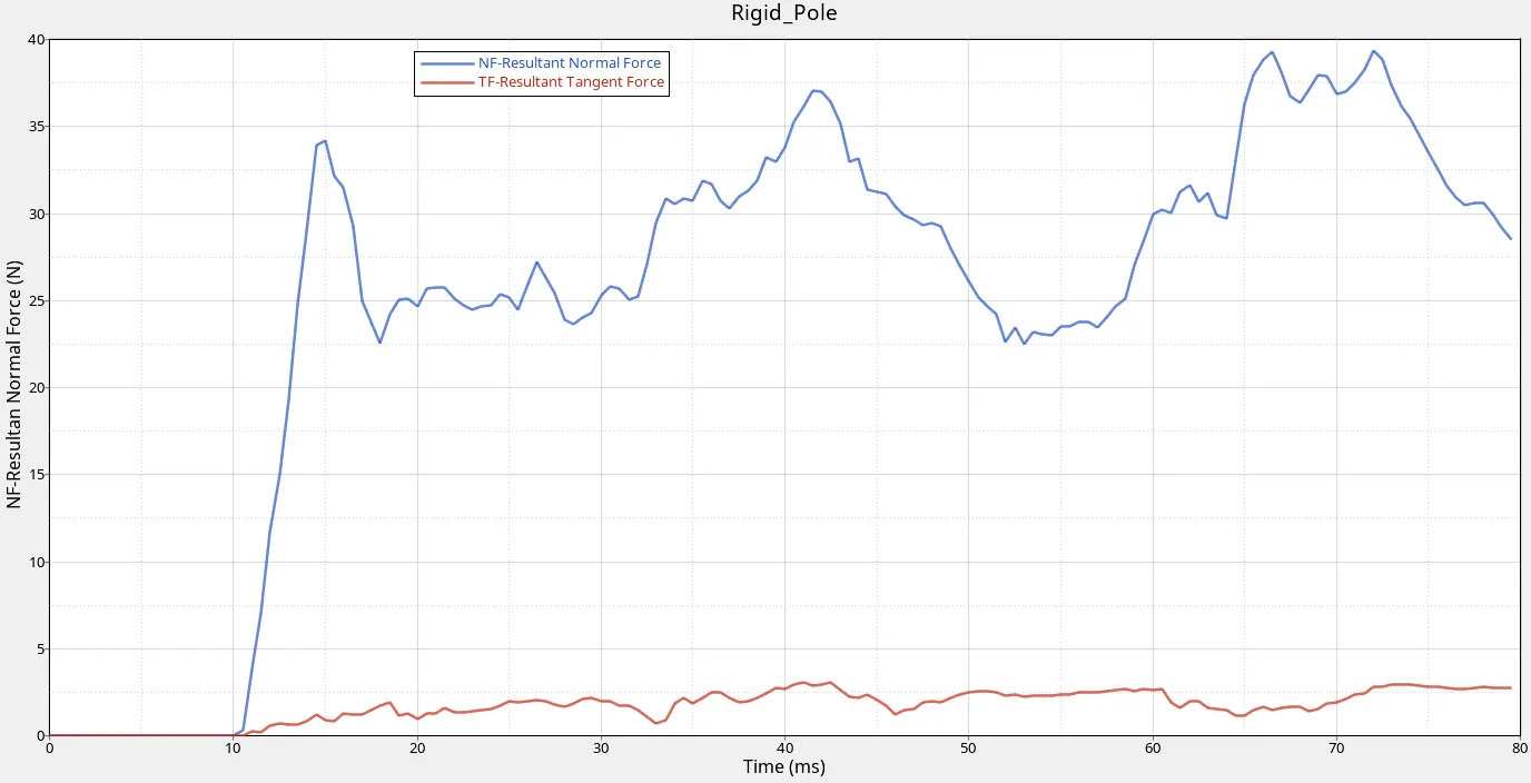
Figure 18: Rigid Pole Impact
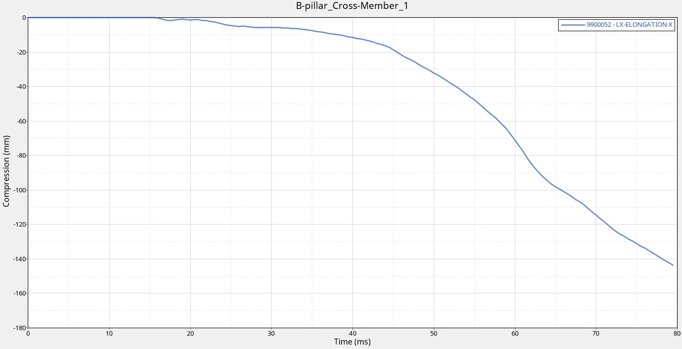
Figure 19: Intrusion in B-Pillar 1
The above shows the variation of B-Pillar impact which is compressed to 1165 mm from 1310 mm.
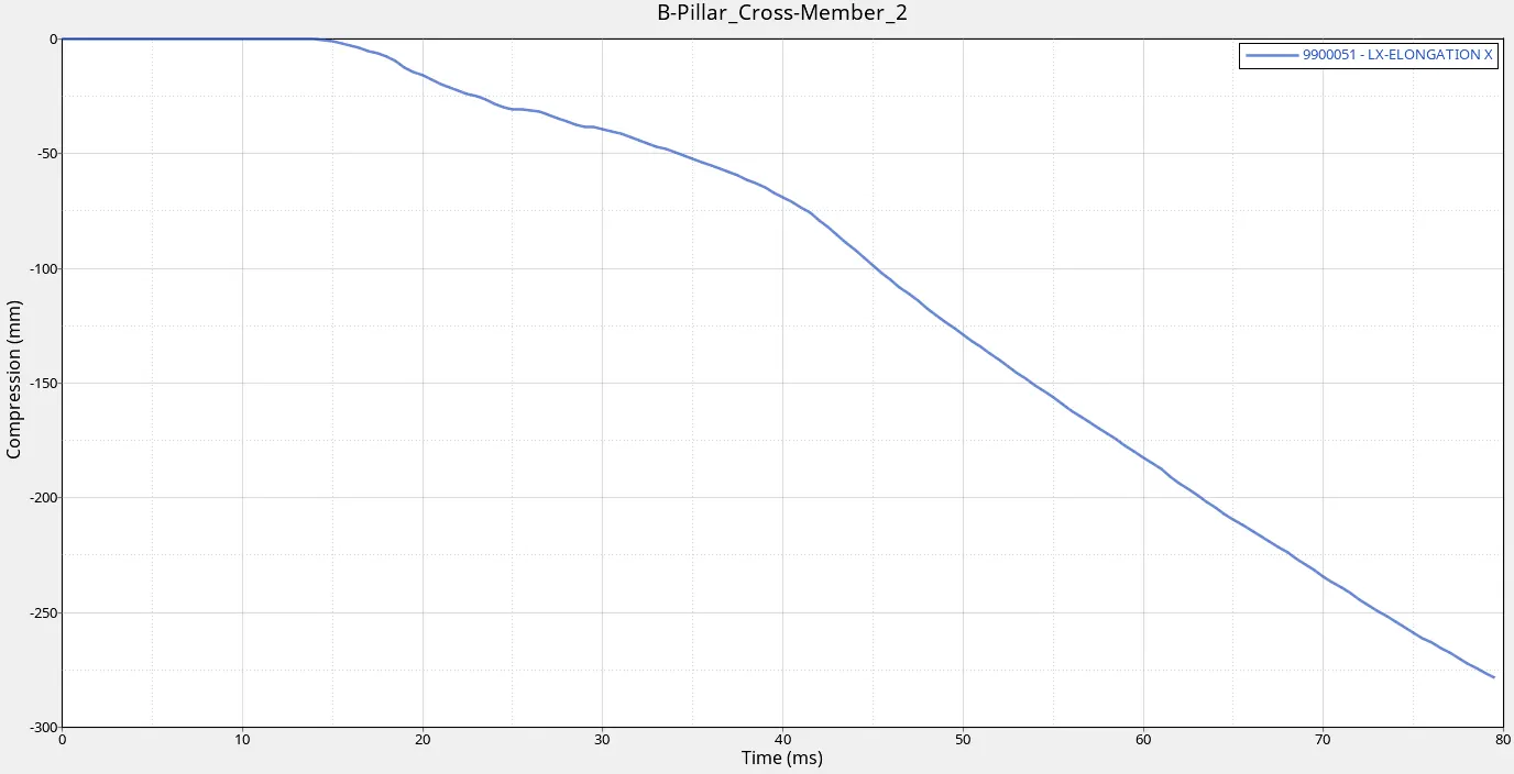
Figure 20: Intrusion in B-Pillar 2
The above shows the variation of B-Pillar impact which is compressed to 1030 mm from 1310 mm.
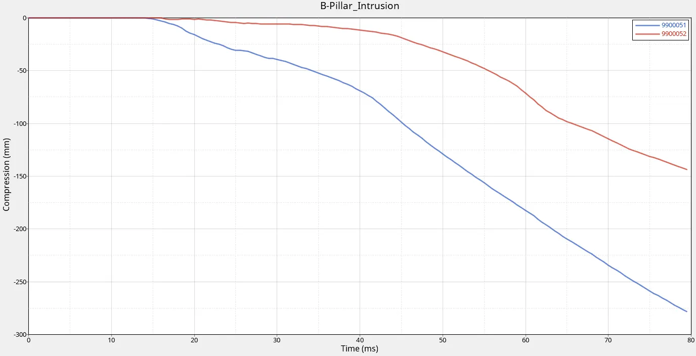
Figure 21: Comparison of 2 points near cross member in B-pillar
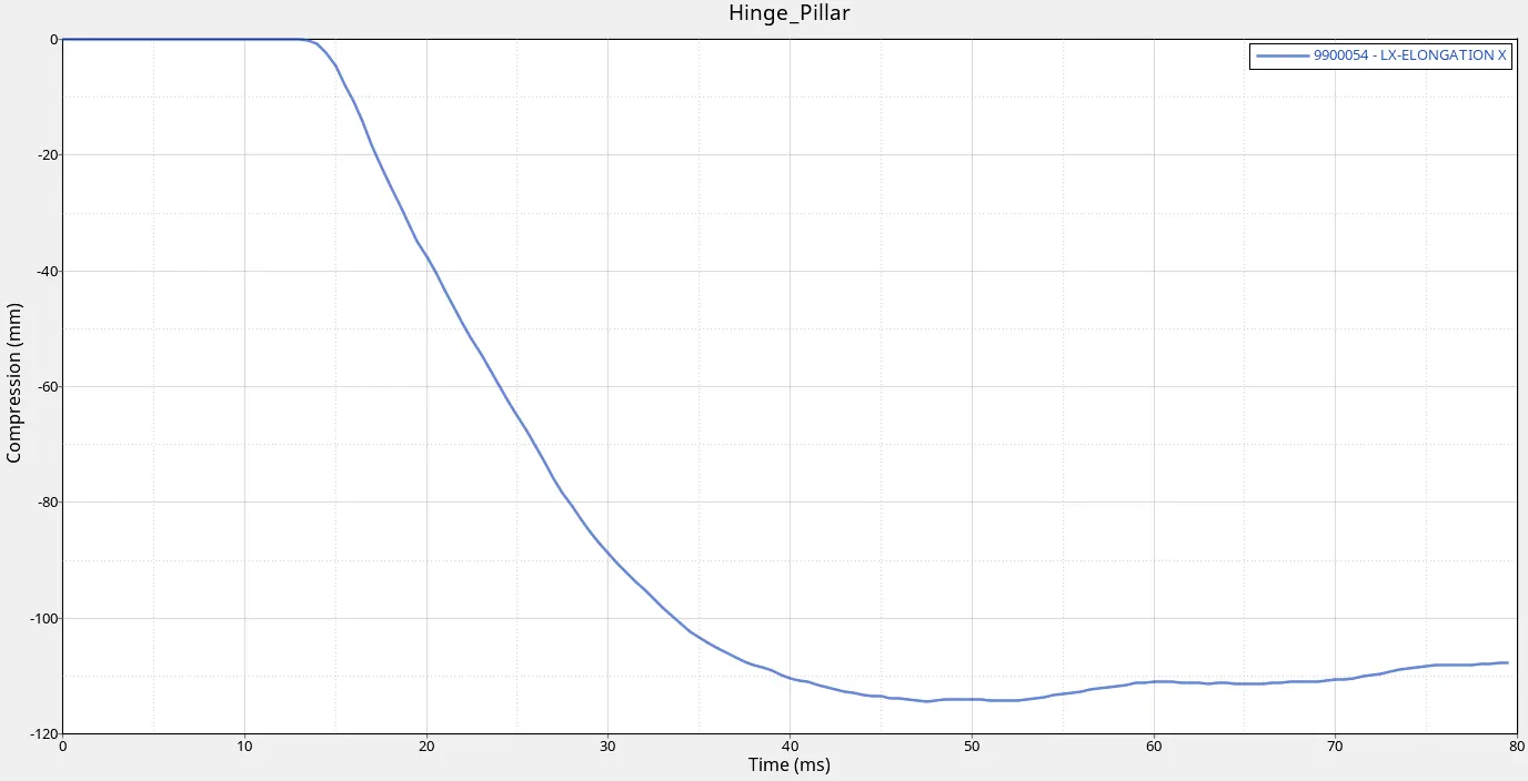
Figure 22: Compression in Hinge Pillar
The above shows the variation of Hinge Pillar impact which is compressed to 1200 mm from 1310 mm.
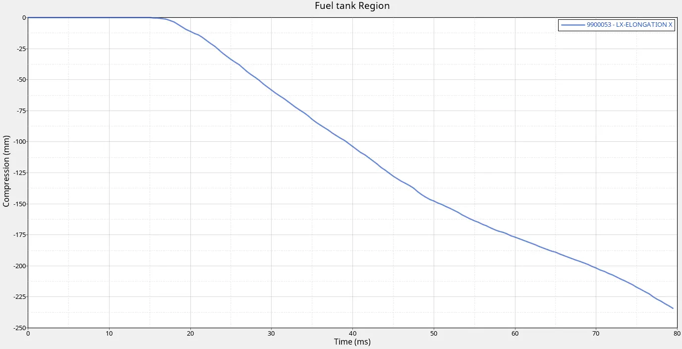
Figure 23: Compression in Fuel tank region
The above shows the variation of Fuel tank region impact which is compressed to 1080 mm from 1310 mm. It can improve by strengtining the material and allocate the fuel tank region.
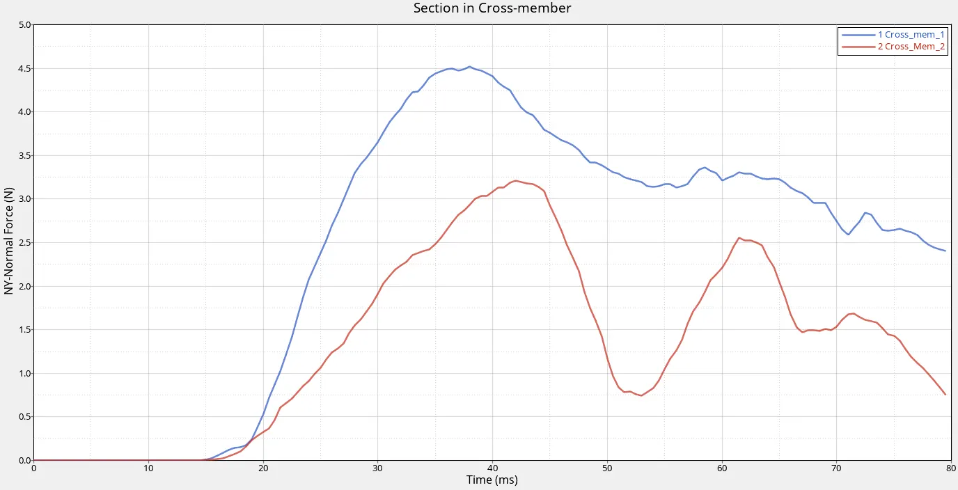
Figure 24: Section in Cross members
The Above figure shows the impact on the Driver side where sections are created in cross members where there is fluctuation due to force acting on Door and member and also mass distribution. The max Normal force in Y direction is 4.5 N and 3.3 N respectively.
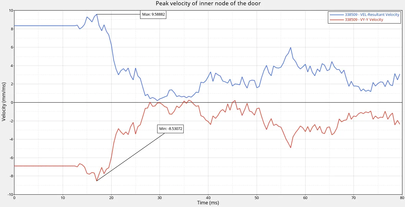
Figure 25: Peak Velocity of Inner node of the Door
The above figure shows that the velocity travels in a inner node of the door when impacts to the rigid pole at a velocity of 8.33 m/s. Here the max velocity reached or identified in the inner node by taking resultant force (9.58 m/s) and Velocity in Y direction (8.5 m/s).
CONCLUSION:
The model has been imported to the Hypercrash / Hypermesh.
The model has checked for Free parts, Penetration & Intersection.
Added mass to locate proper COG.
The rigid pole is created based on the standard.
Sections & Intrusion are created and obtained the results accordingly.
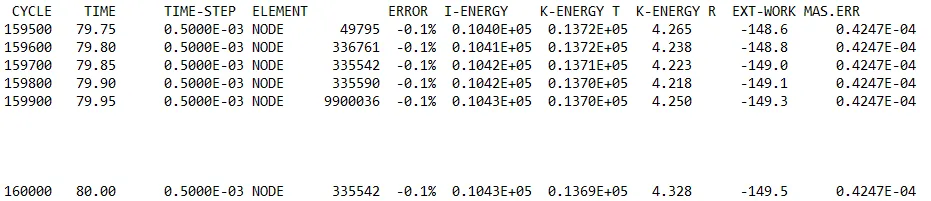
The energy error obtained as -0.1%, No. of cycle is 160000, Time elapsed is 6870.86 secs, Mass error is 0.4247e-4 and the simulation completed with Normal termination.