SIDE CRASH ANALYSIS
AIM:To perform a side crash simulation and operation in a neon BIW model along with the analysis of various output which can be taken out after giving the Radios to it.
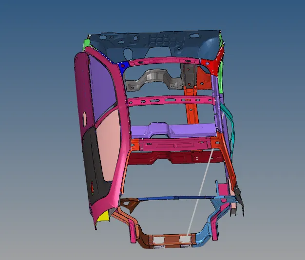
PROCEDURE:(a)The model in which we have to perform the whole operation for side crash are shown below:
Let us check the unit system as shown below:
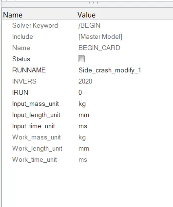
in the model mode >Begin cards we can be observe the unit system which are being asked.
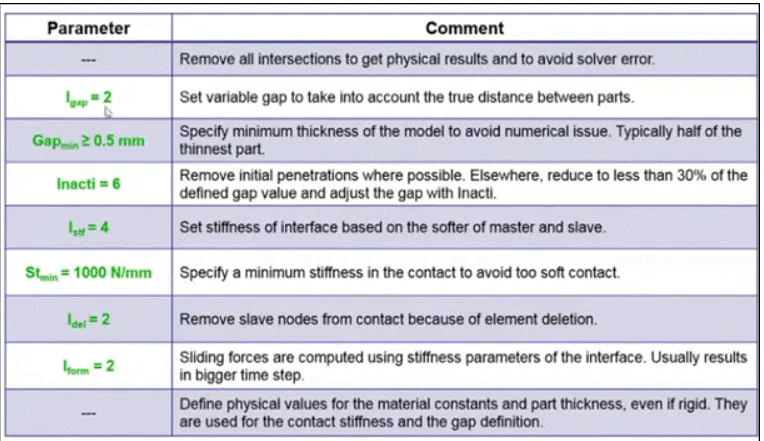
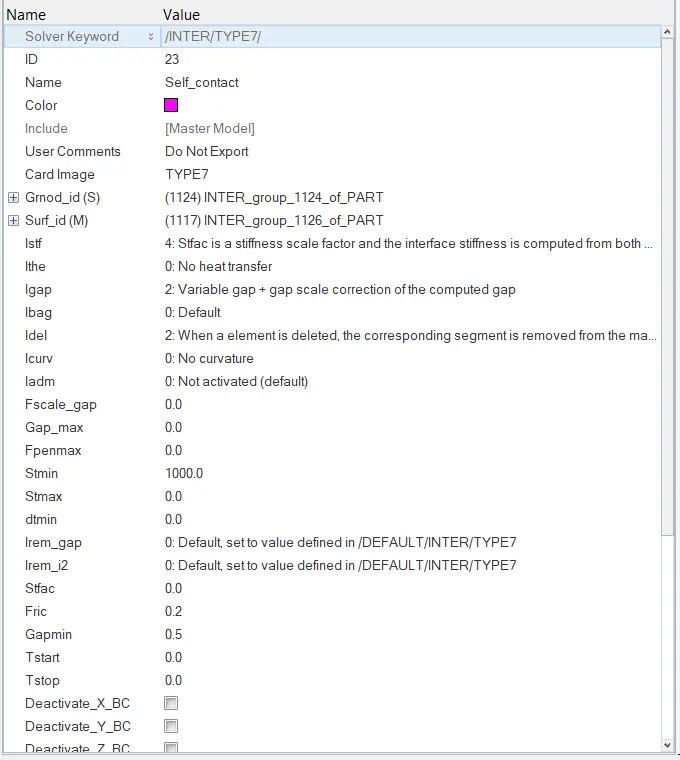
(b)In order to have the Interface we gotta go Create>INTER>TYPE7 and the rest of the interface those are BY-default needs to be deleted.And there are some standard values which has to put inside the type-7 interface.Those are:
(c)Now moving forward to check the penetration and intersection in the hypercrash we go to QUALITY CHECK>CHECK ALL SOLVER CONTACT INTERFACES.
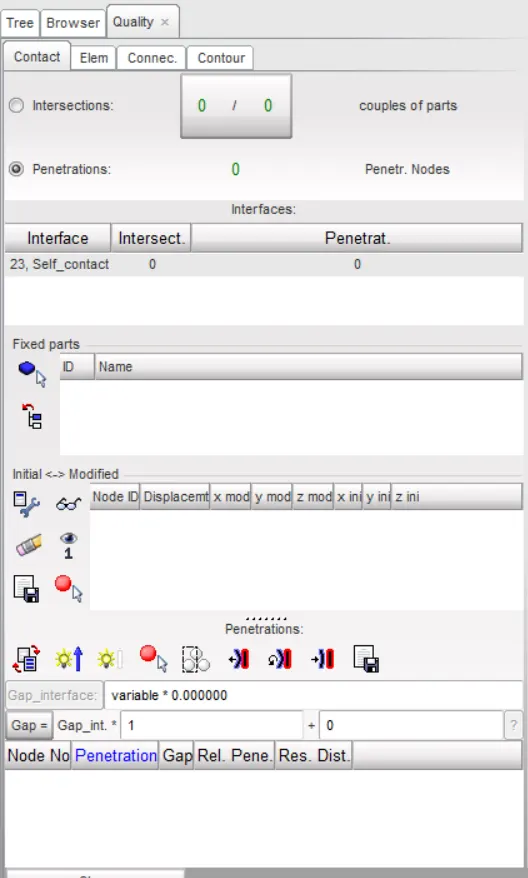
by using this checker option we have got the information that there is no intersection and penetration at all.
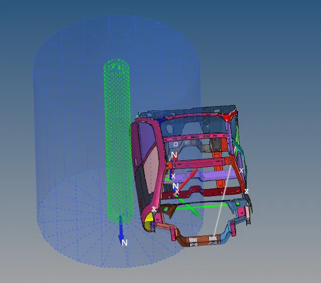
(d)So creating the rigid wall is done by CREATE>RWALL>CYNLINDER and all the required details will be added in it.
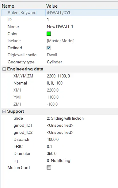
Dsearch should be 1000 as it can be considered for a slave also in order to get rid off the incompatible kinematic conditions such things create the error upto -99% ,so assigning the slave has been done with the help of Dsearch which are lesser stiffer compare to master.
(e)The full scale model has been shown below with total weight of it 1216.5kg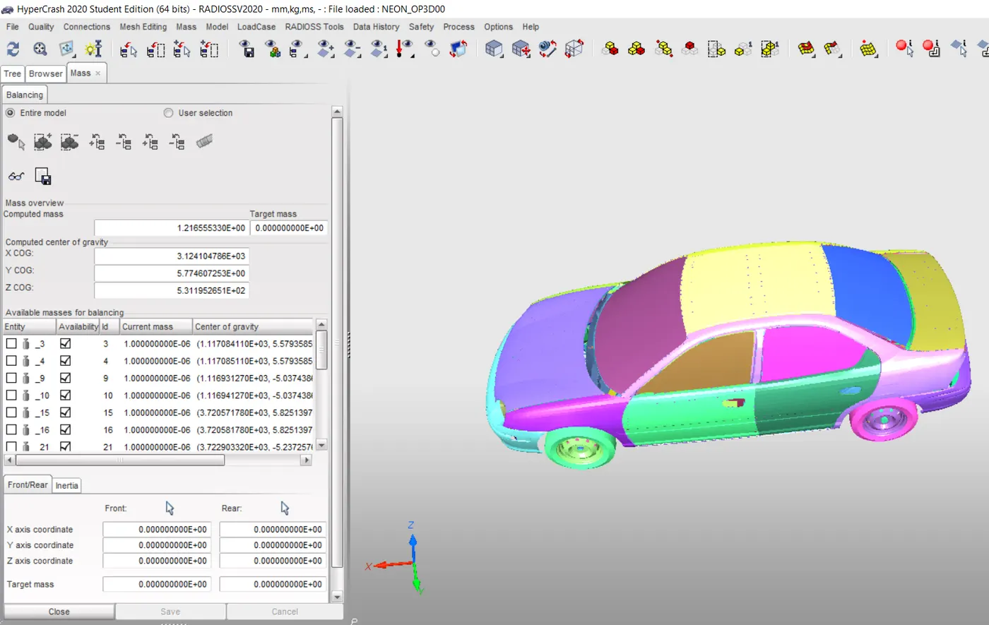
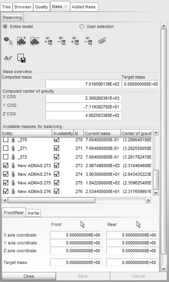
Now the task is to get the working model to 700kg and making the CG at the desired location to do that in hypercrash we gotta go towards 2 options in the first MASS>BALANCING and in the second LOAD CASE>ADDED MASS.By this icons are get opened we introduced 4masses in the cross member ,b-pillar and hinged pillar to get CG in the desired form.
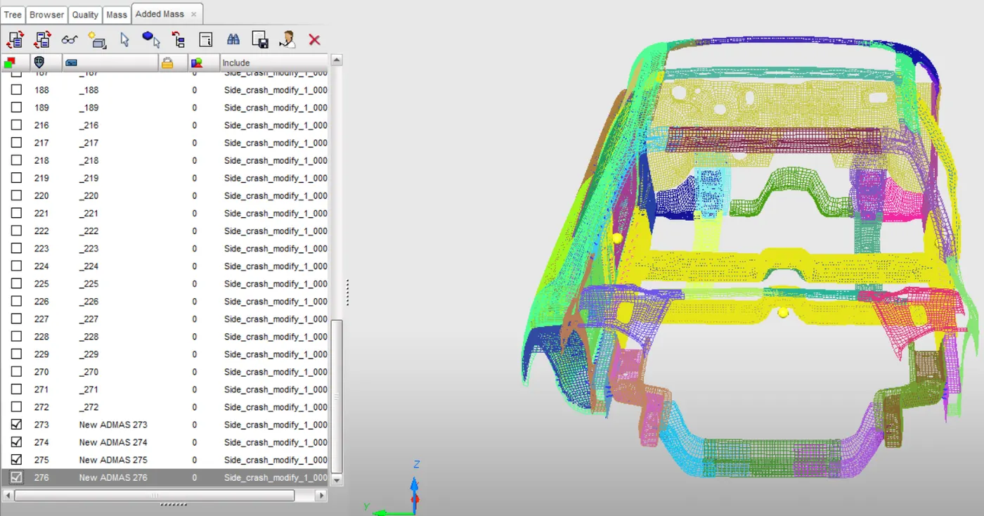
And in the added mass section we have got the desire result depicted below:
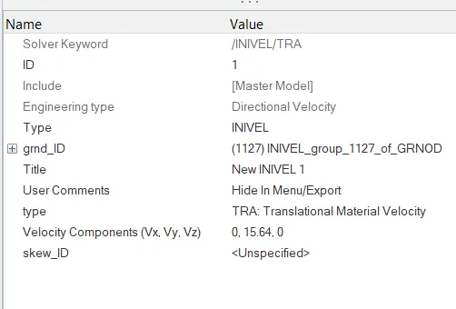
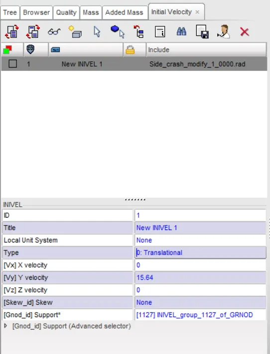
(f)Now after completion of the following steps we gotta add initial velocity,LOAD CASE.INITIAL VELOCITY ,now we have the velocity is 35mph which is being converted into mm/ms i.e 15.64mm/ms.As shown below:
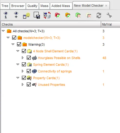
(g)Proceeding ahead to see model checker to remove all the error and make the model should be error free before introducing it in the simulation.In hypercrash we go to QUALITY>NEW MODEL CHECKER and run, the error is being eradicated firstly imposing autofix tool and then if some error could not eliminated can be done by directly deleting it.Following such details we have the result Shown image below:
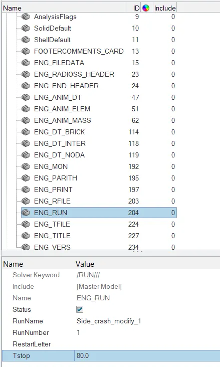
(h)Under Cards ENG_RUN in model mode:
(I)Creation of section in hypermesh CREATE>SECT by doing so we have created it after that we got to create a frame CREATE>FRAME>MOV ,from this N1,N2,N3 will be taken and being put to section,then in section we have Frame id in which we have to select the id which is being created ,now in section we have the option grshell_id we have to create it assigning the entity_id

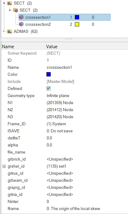
Likewise there are 2 section along with 2 frame needs to created in crossmember those are depicted below:
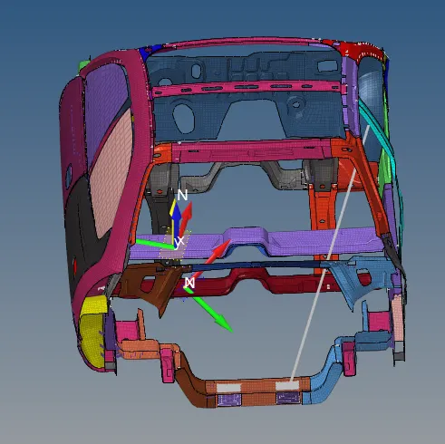
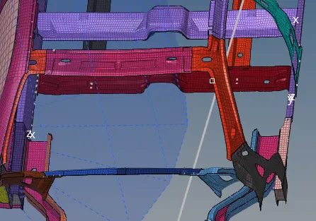
(ii)After to it we proceed to create skew again CREATE>SKEW>MOV.Skew is need to create for the intrusion to the given node:
The skew has got created at b-pilar and cross member are shown below:
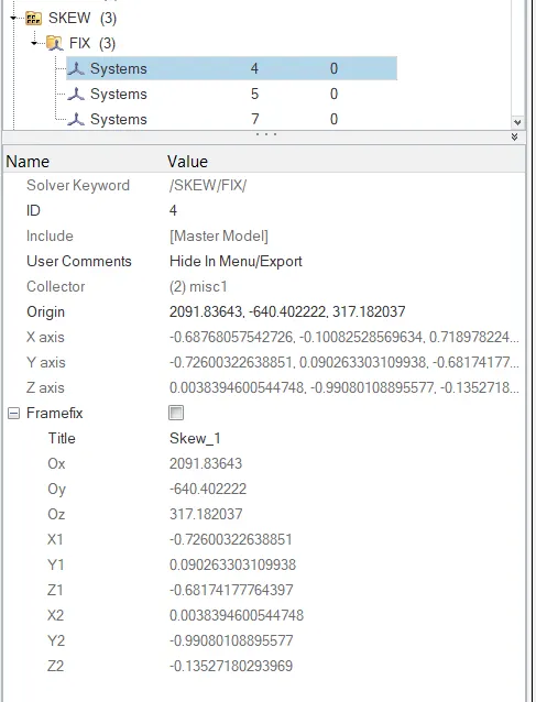
Now after all these things gets completed we gotta go towards output block which consider the things for consideration those are listed below:
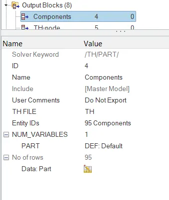
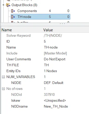
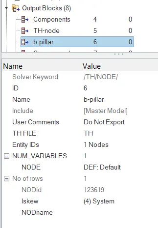
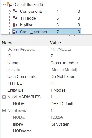
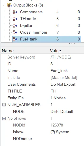
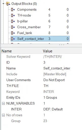
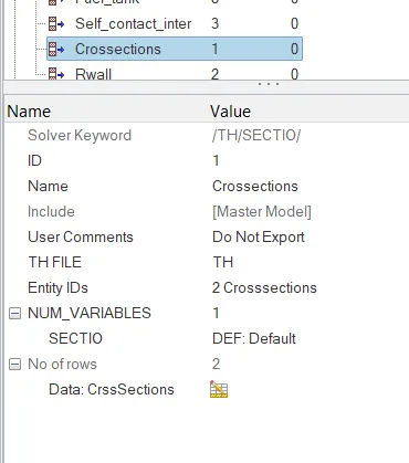
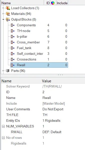
(J)After doing all the neccessary procedure we gotta go for RAD OUT file of 0001 to take a look to various things which shown below and defined below:
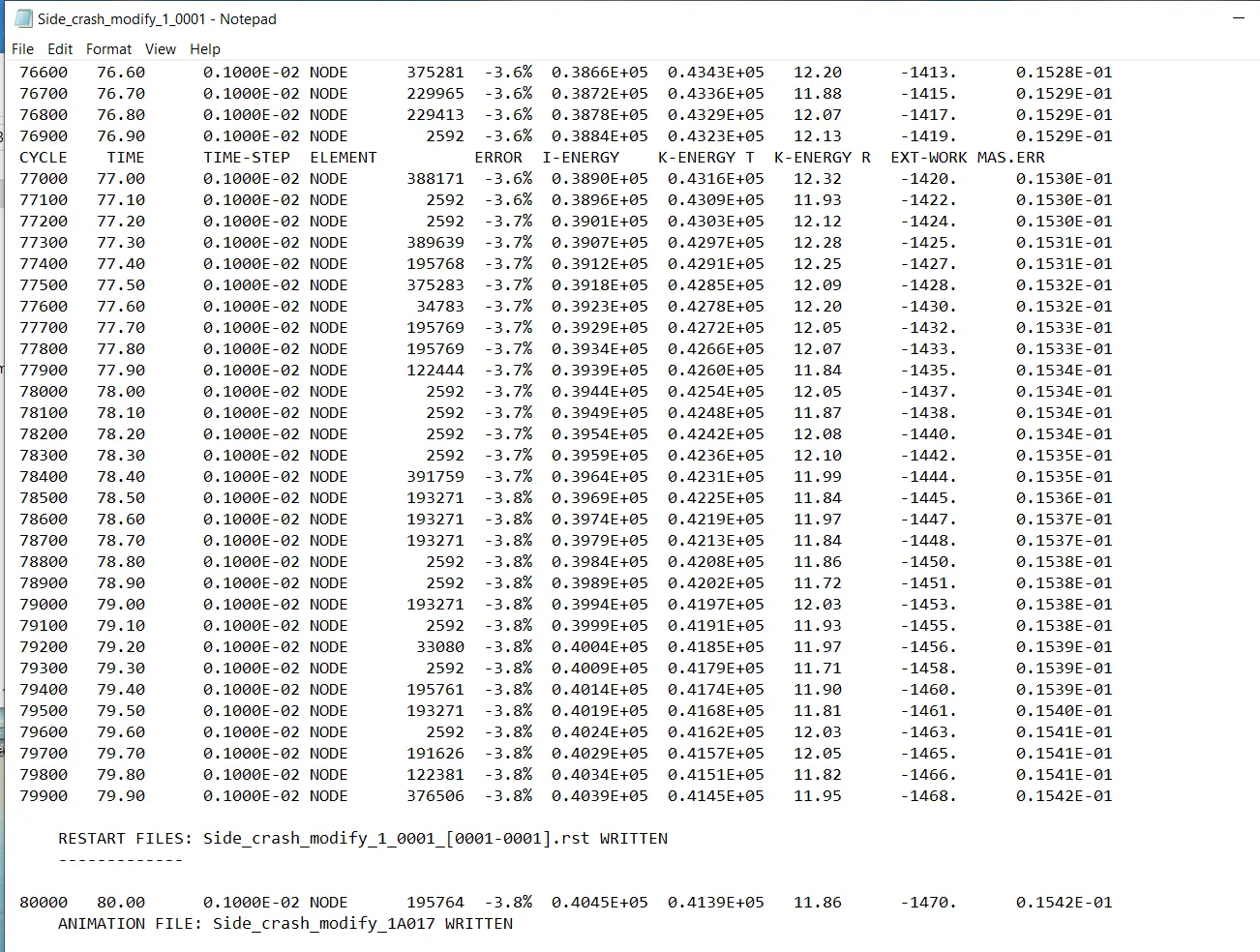
(i)No. of cycles=8001
(ii)Elapsed Time=3337.71sec.
(iii)Energy Error=-3.8%
(iv)Mass error=0.1542E-01
So the simulation is taken for consideration as tells that energy error are acceptable it lies in between the -15%-5%.
(K)Shifting the mode towards the hyperview in order to have a h3d file for animation point of view:
Shift to contour mode:
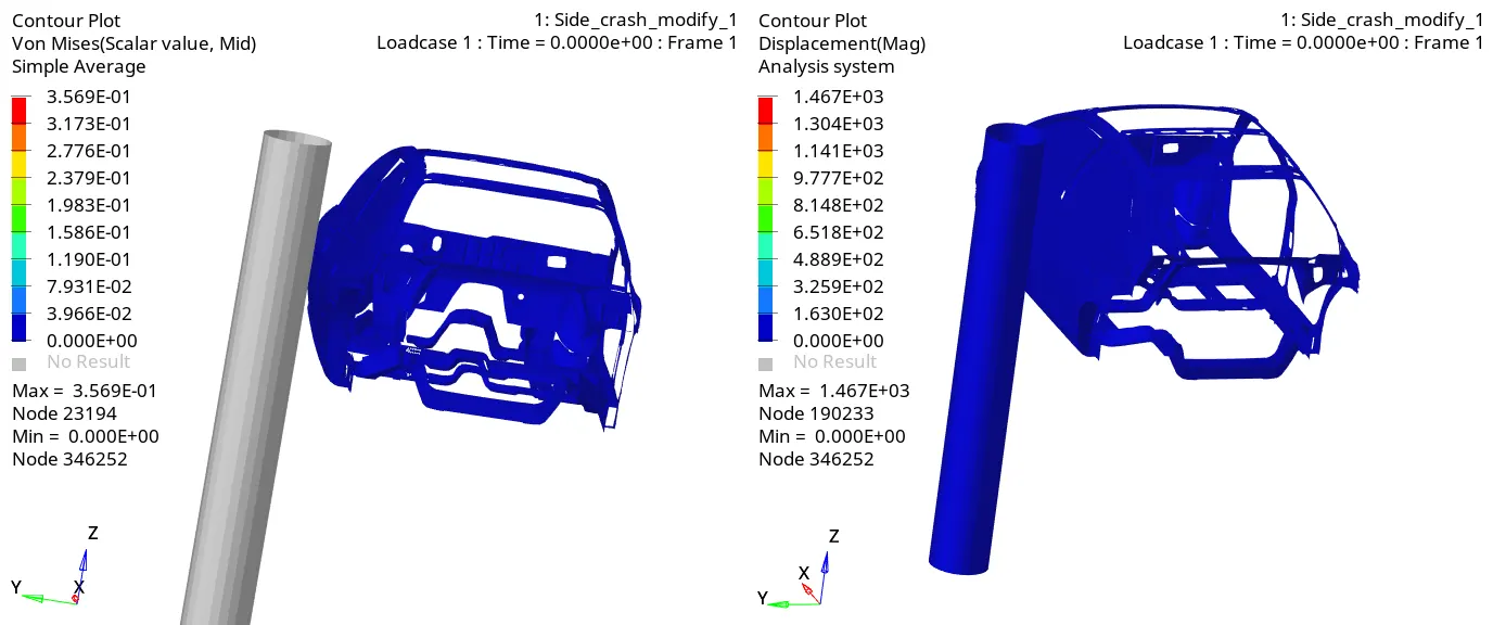
Here it can be clearly observed that 356MPa would be the max.von mises stress and 1467mm is going to be a max.displacement.
(K)Now shifting the mode towards the hypergraph 2D to get the graphical representation of the various criterion that we have got as shown below:
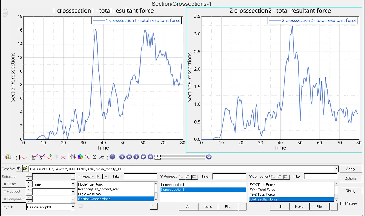
This graph represent the Crossection having the total resultant force in which crossection_1 having 16KN of force and the crossection_2 is 3.3KN.This force tells the impact holds by a respective component and the graph shown variation of force applied in it.
The next graph that we have for the intrusion is nothing but the uninvited interuption,here it is measured in terms of displacement of the dash wall towards the stiffer wall and form the deformation as shown below in terms of intrusion1(b-pillar), intrusion2(cross-member) and intrusion3(fuel_tank) which is based on the points considered in the assembly.
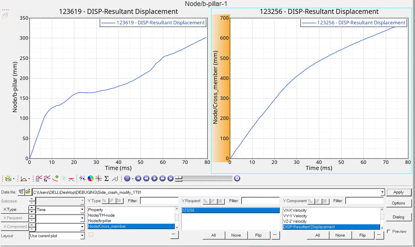
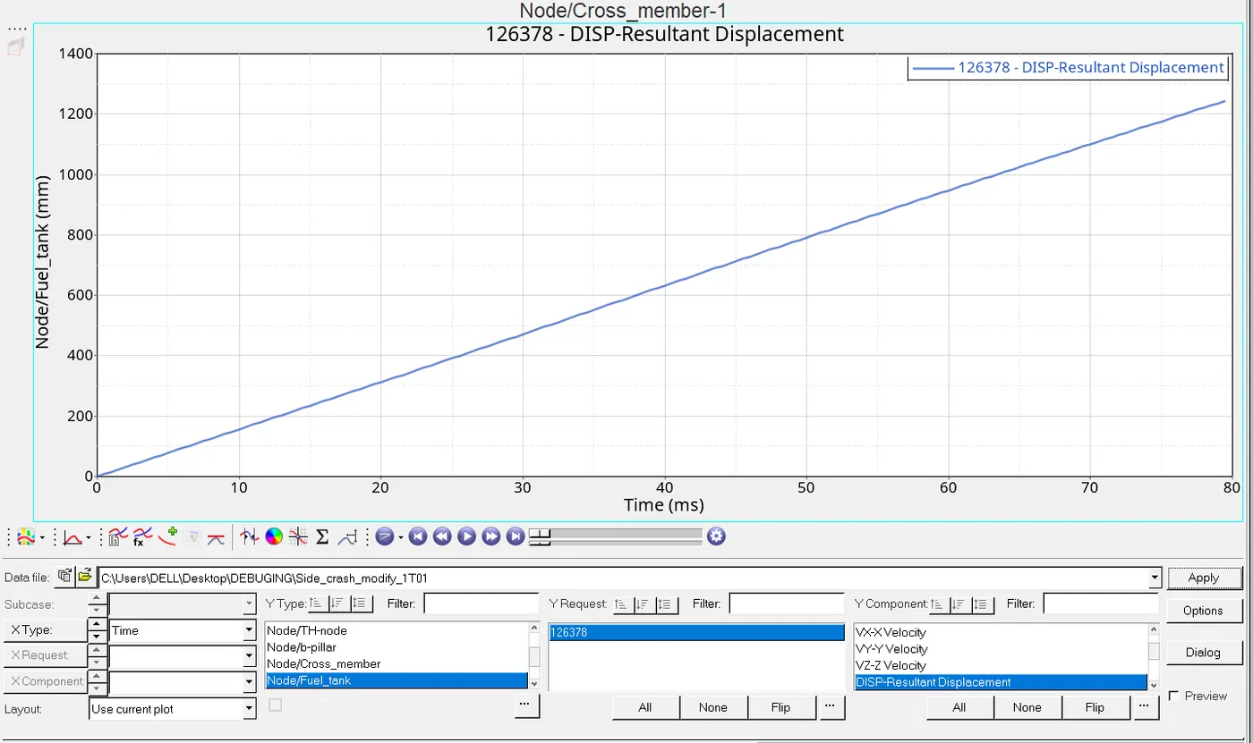
So these are points taken inside the dash wall which shows there own distortion behaviour with max. displacement of intrusion_1 is 320mm and beside to is intrusion_2 is somewhat 700mm. also 1200mm in the intrusion_3 which is a fuel tank.
Lastly the last depiction graph is energy variation shown below:
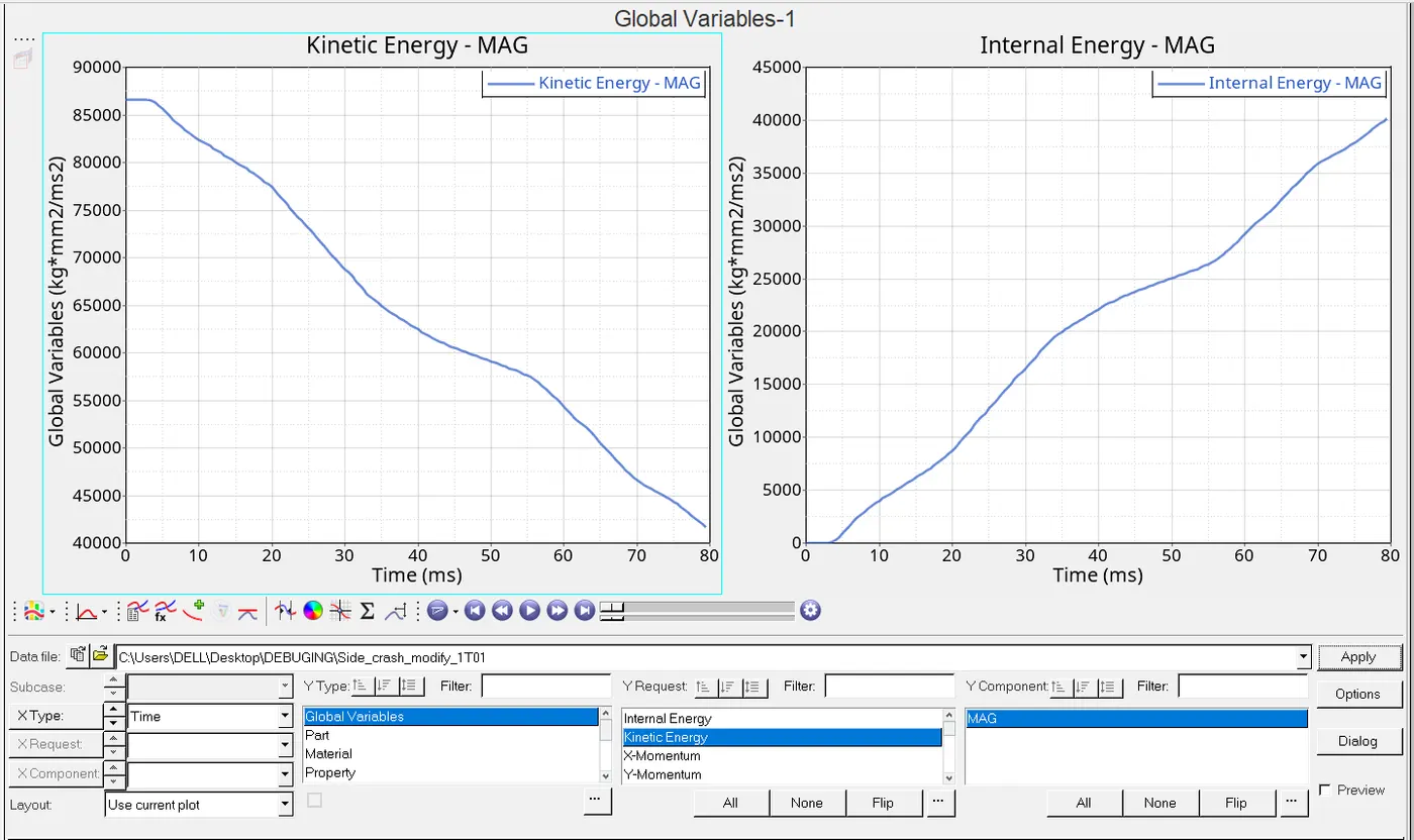
So let us take these energy ,so it is very obvious to know that KE will be decreased due to collision of assembly which signifies in the graph because impact causing kE to get transfered into IE ,it is simple phenomenon steady flow of energy equation ,here there is no heat transfer ,no potential drop but yes it do have work output ,so it can be said KE gets transfered in IE and workoutput.So here max value of KE is 8700KN-mm and IE 4000KN-mm.
EXPLANATION:Type_7 is a general-purpose interface and can simulate all types of impact between the set of nodes and the master surface. A slave can belong to the master surface and auto impact possible. The contact gap can be constant or variable.Here we have taken self contact,Type11 contact is less accurate as compare to type7 which is considered above.
Intrusions can be introduced by spring method also MESH>CREATE>1D ELEMENT>SPRINGS then we gotta go to Property to create under to it we can assign mass ,stiffness and many other parameters then under components we have auto under that we assign property_id which we have created and then at last got to create outputblock of spring and in it element has been taken as spring.
CONCLUSION:
(a)Here we have got to know about the energy phenomenon how it works in the section of b-pillar,cross member and hinge-pillar and how much it bear and how much it transfered it.
(b)Also knew about the intrusion having in fuel tanks,pillar and cross members along with where it has to put to get the output.