Side pole crash analysis of Dodge Neon using RADIOSS
Side pole crash analysis of Dodge Neon using RADIOSS
AIM: Car Sidecrash analysis of Dodge Neon BIW using RADIOSS.
- Check the unit system and either follow [Mg mm s] or [Kg mm ms].
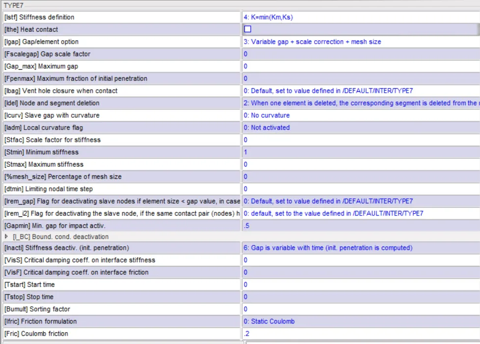
- Create an appropriate interface, friction 0.2, and recommended parameters.
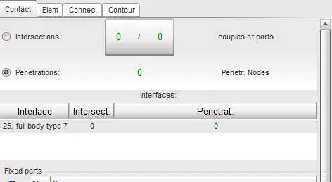
- Make sure of no penetration and intersections.
- Create a rigid wall with friction 0.1 as per the reference model.
- Compare the model weight with the reference model and use added masses to reach the target weight 700kg while getting CG about the required range.
- The initial velocity of 35 mph.
- Use model checker to ensure good quality.
- Timestep :0.5 to 0.1 microseconds.
- Run 80ms.
Plot the following outputs
- Sectional force in the cross member.
- The intrusion at B pillar, hinge pillar, and fuel tank region. Provide recommendations on what can help to reduce Fuel tank intrusion.
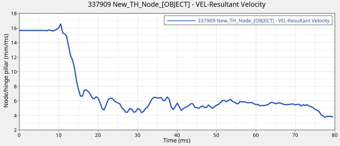
- Peak velocity of the inner node of the door.
PROCEDURE:
Import model
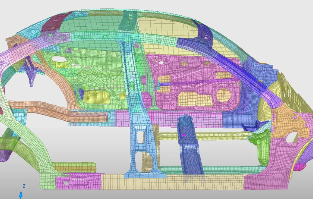
On importing the _0000.rad file into Hypercrash we get this partial reduced BIW model for performing side crash test. 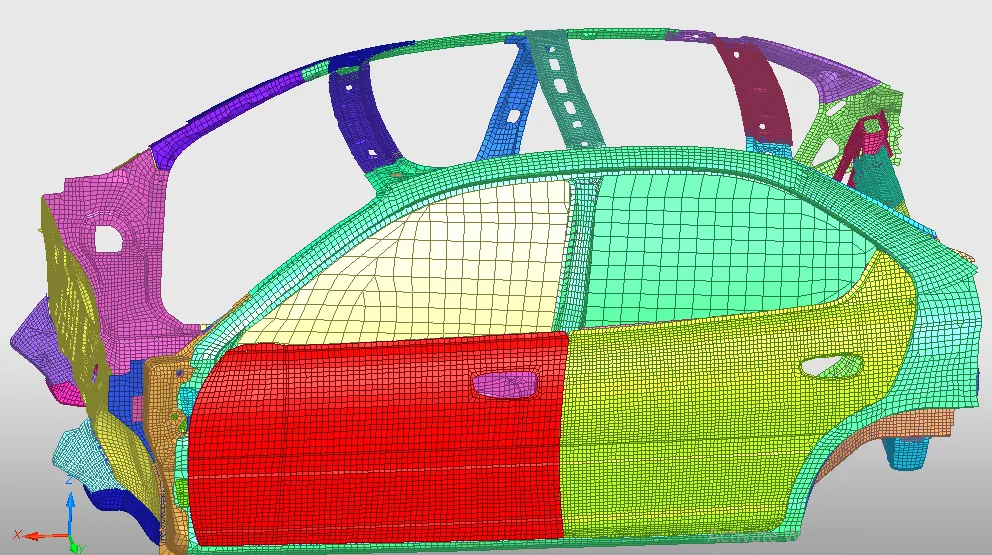
1) Check the unit system [Kg mm ms].

On opening the _0000.rad file we can see the unit system which is followed here is [kg mm ms]
2) Create an appropriate interface, friction 0.2, and recommended parameters.
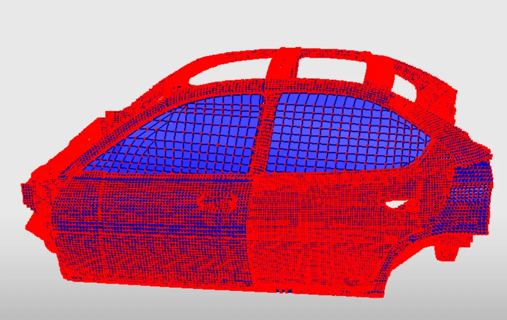
We provide a self impact TYPE 7 interface over a full body by providing recommended parameter values as shown below
3) Make sure of no penetration and intersections.
Before moving to the next step we will make sure there are no intersection or penetration of elements. If any fix them by using the tools provided in Hypercarsh and HyperWorks. since there were no penetration or inetrsection during the check we can proceed furthur.
4) Create a rigid wall with friction 0.1 as per the reference model.
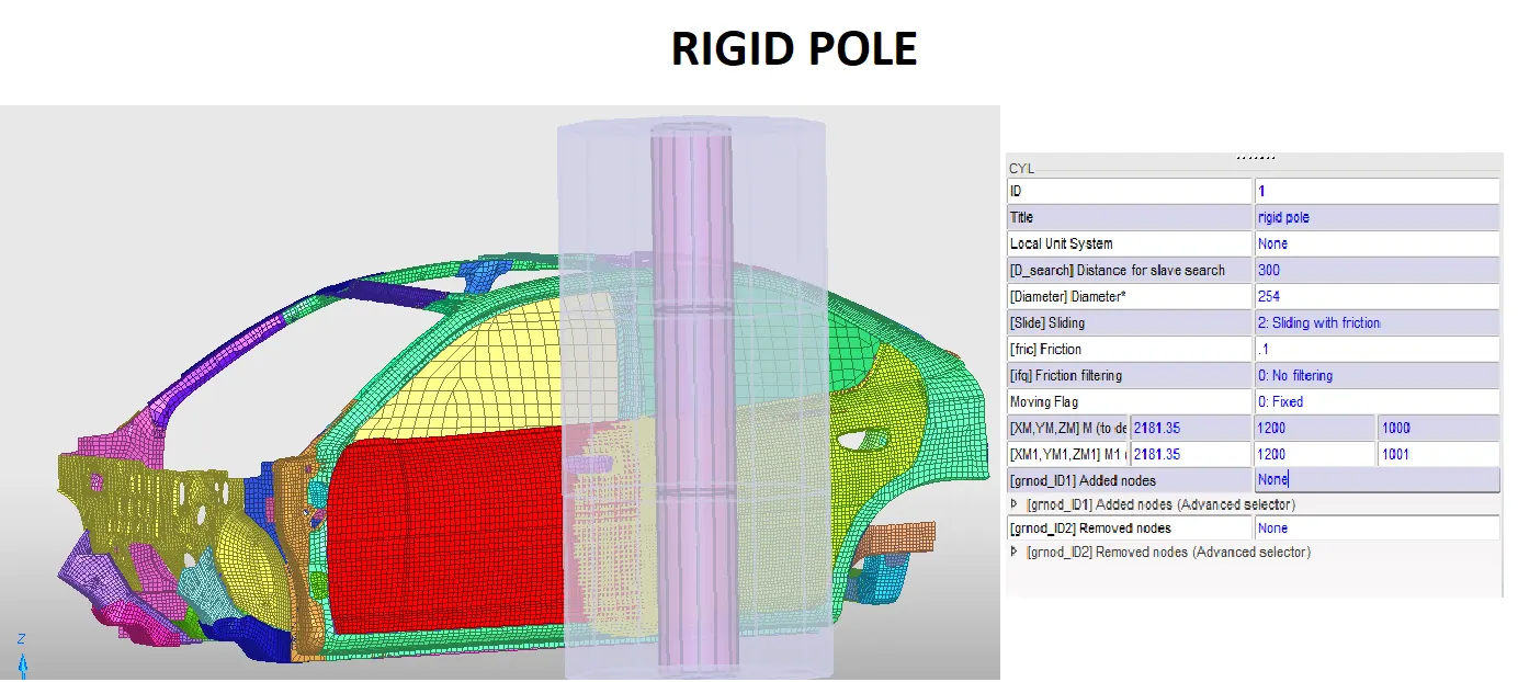
We are providing the cylindrical rigid pole with [fric] Friction value to be 0.1, search distance 300 and diameter as 250 mm at a perpendicular distance away from the B-pillar.
5) Compare the model weight with the reference model and use added masses to reach the target weight 700kg while getting CG about the required range.
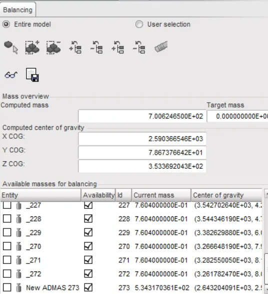
On checking the mass balancing in the HyperCrash we see the total weight of the model is 166 kg and COG somewhere near the B-pillar cross member mid region inorder to make the mass near to the 700kg we need to add mass so we added the 536 kg to the rocker cross beam so as to make the COG point over near to the rocker cross beam. As shown in the figure below.
6) The initial velocity of 35 mph.
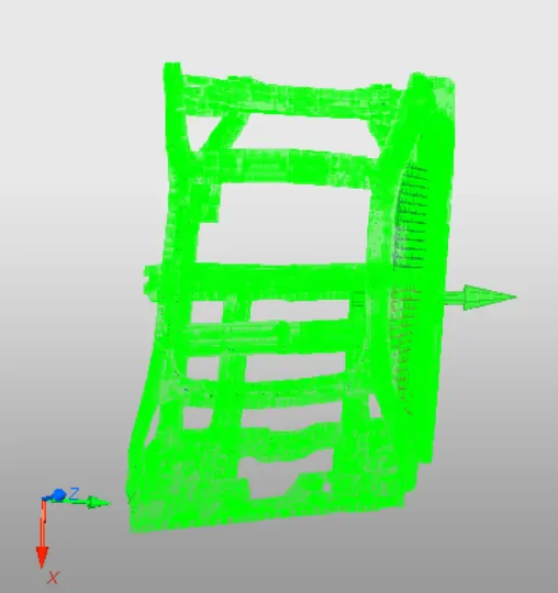
we need to provide the initial velocity of 35 mph which equal to 15.64 mm/ms to the full vehicle body in a positive y direction towards the pole.
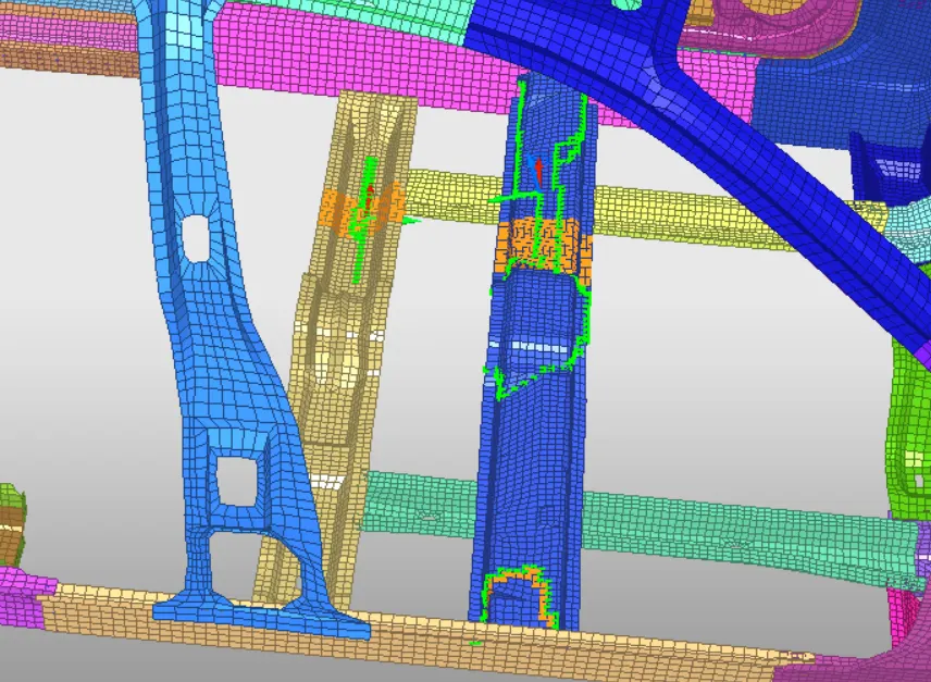
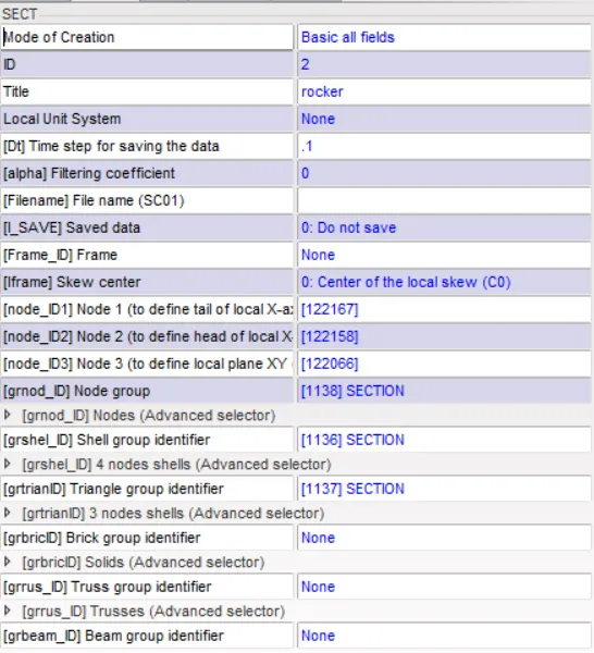
7) Cross-section setup for cross members.
To know the sectional force over the areas such as cross members we need to give section over the elements as shown below. The sections are provide using a moving frame.
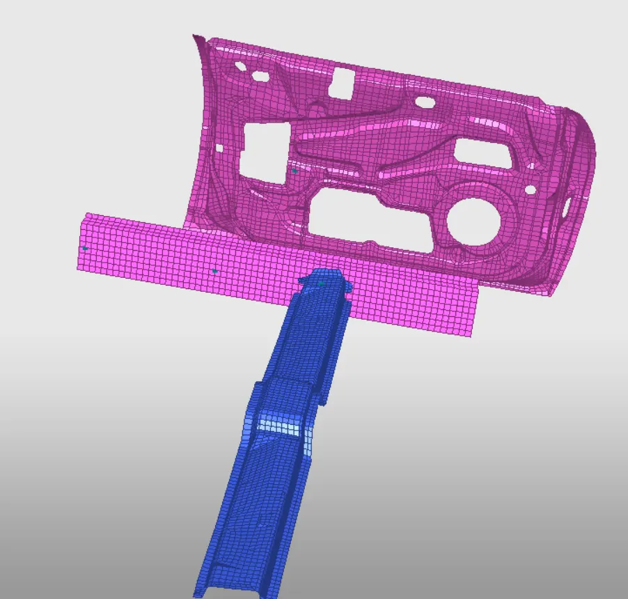
8)Intrusion nodes
To know the intrusions over the area of crash impact we need to set the TH node for area as shown below.
9) Output TH request and Engine cards
Once we are done providing the setup request we have to request the TH output. such as accelerometer, sections, rigidwall, etc. After we are done with TH output we need to provide engine cards for animation and contour capturing eg. ANIM/DT,ANIM/VECT, ENG_RUN ETC.
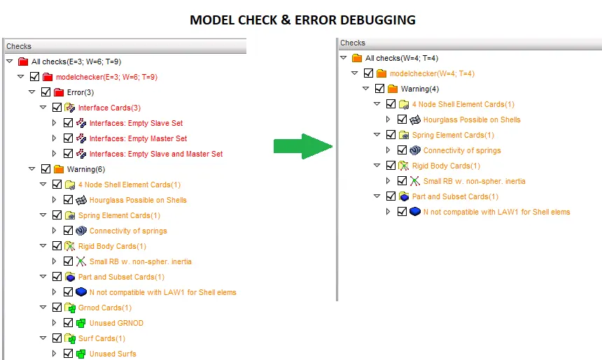
10) Use model checker to ensure good quality.
Finally before generating the radioss simulation and file we need to do the final check i.e model check. On running the model check we see the it shown few errors and warnings so we need to check and fix them. Finally we got the debugging correct and manage to fix all errors.
POST PROCESSING

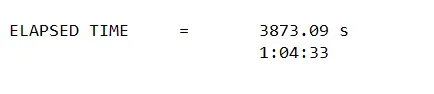
On opening the _0001.out file we can see the energy error to be -1.2% and mass error to be 0.01028 which is acceptable and can considered as good model with total no. of cycle as 79900 with time duration of 3873.09 s.
ANIMATION FILE
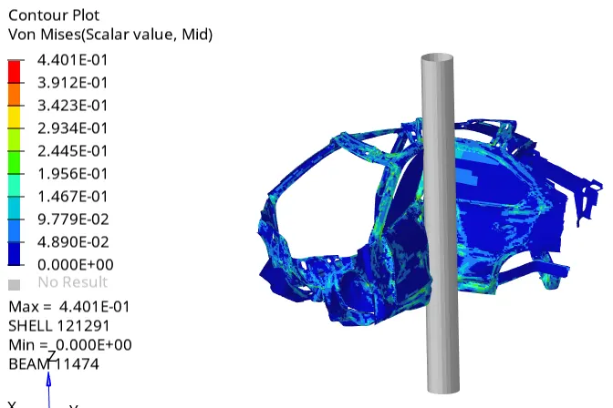
1) Von-Mises stress plot (side view)
Here we can see the value of von-mises stress generated during the impact with side pole, the max value of 0.4401 Gpa.
From the side view we can analyse the stress flow path during the impact absorbed by the B-pillar, sill beam and A-pillar
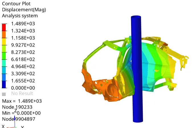
2) Displacement contour plot
The maximum dispalcement achieved is the 1489mm
TH plots
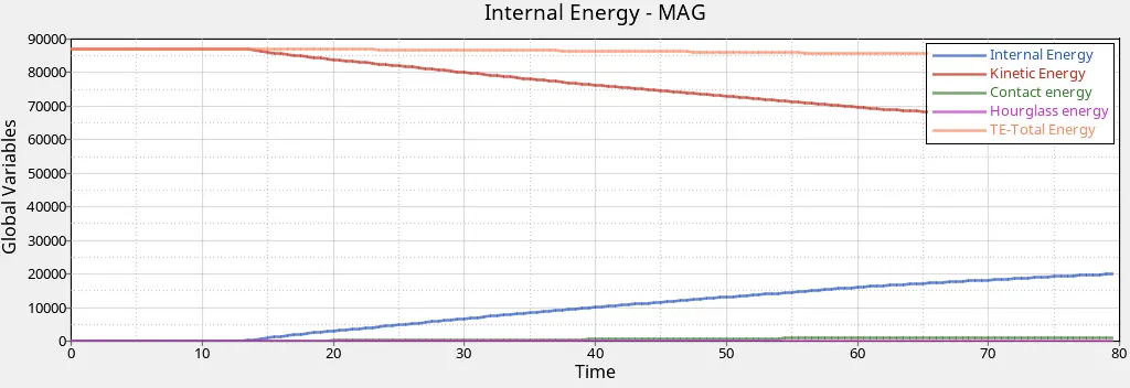
1) Energy plot
As we can see the kinetic energy at the start of the simulation is at 85KJ and reduces gradually with the impact into the rigid wall(velocity reduced). The Internal energy start at 0 and increases to a value of 20KJ at the end of simulation due to the deformation and conversion of K.E to I.E. The value of hourglass energy is zero throughout the simulation due to the use of recommended shell properties. and contact energy is insignificant.
2) Rigid pole forces
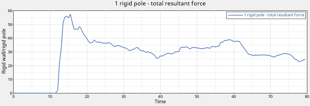
As we can see the plot below shows the total resultant force variation w.r.t simulation time. As it can be seen in the starting the pole force generated is zero till 12ms of simulation because of no contact but at the 15 ms there is peak rise in the wall forces to a value of 58KN and then at 20 ms. Then from 25 ms to 80 ms the value remains almost constant in between 30-40 KN value.
3) Section Force Rocker beam
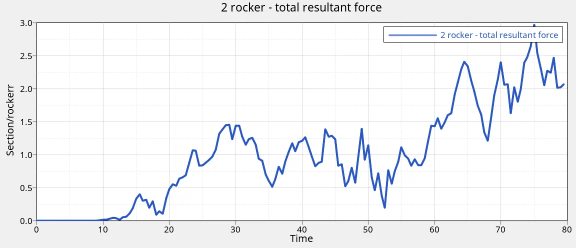
The variation in section force at the Rocker beam is shown below. it starts with the value of 0 till 11ms and then shows variation between 20 to 80 ms with max value of 2.98 KN at 75 ms. This is because of continous crushing of beam into the rigid pole.
4) Section Force cross member
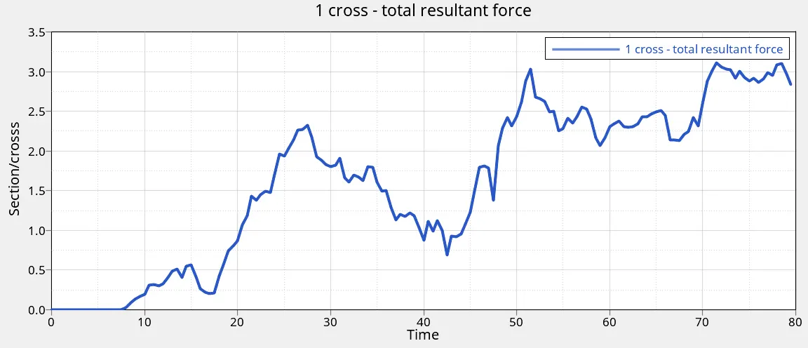
The variation in section force at the B-pillar cross beam is shown below. it starts with the value of 0 till 8 ms and then shows variation between 9 to 80 ms with max value of 3.1 KN at 72 ms.
5) interface normal forces
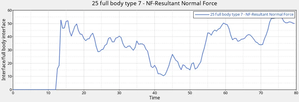
The interface normal force generated due to self impact is shown below in the graph with sharp increase in the value of 53KN after 13 ms of simulation. Then at the near to the end of simulation the value reaches to 55 KN at 75ms.
6) Intrusion on nodes at different sections
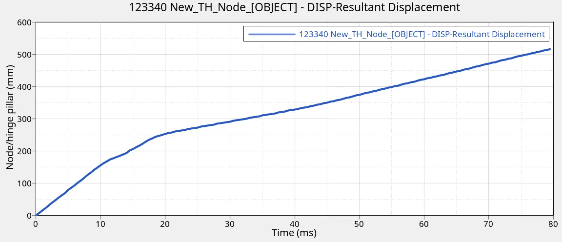
B pillar intrusion = 523 mm
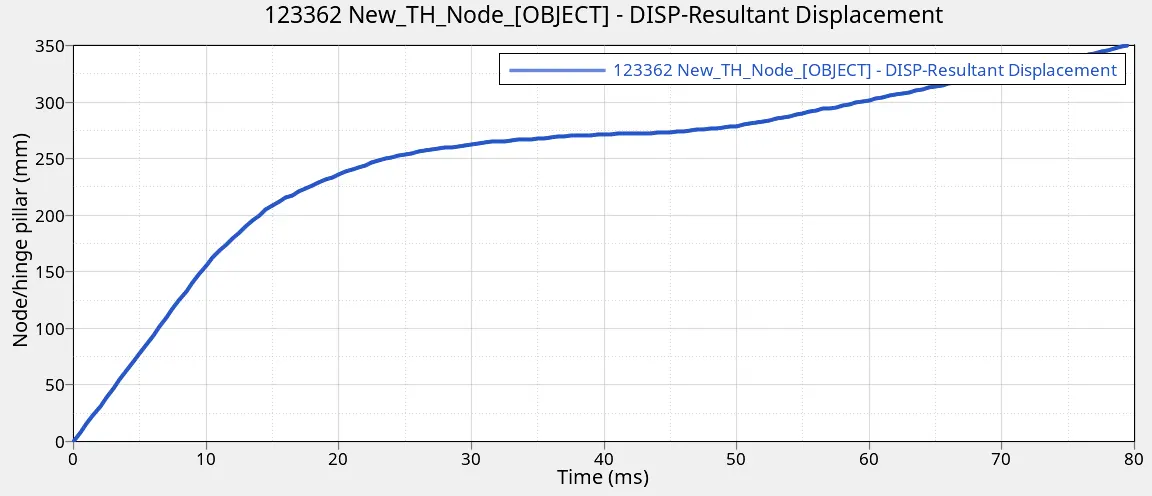
Fuel tank intrusion = 350 mm
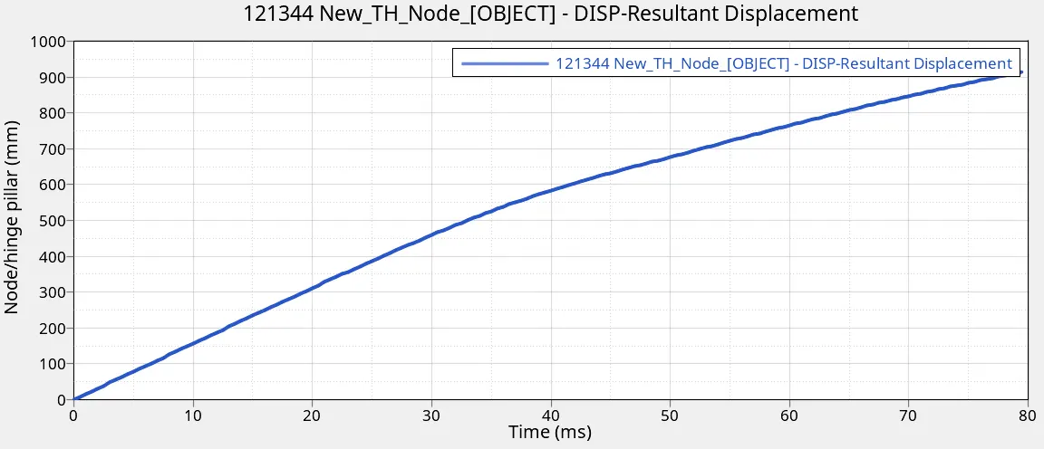
Hinge pillar intrusion = 921 mm
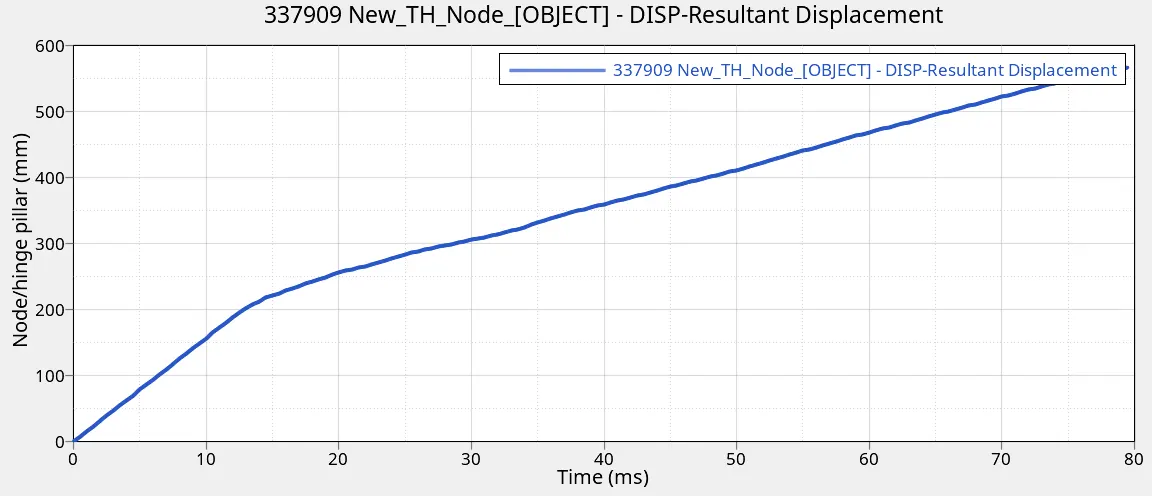
Node 337909 intrusion = 550 mm
So to reduce the intrusion at the fuel tank area the cross members and the sill beam need to be more robust which can resist the deformation and play a major role in occupant safety.
7) Peak velocity of node at the inner door
The peak value of the inner door panel node(337909) velocity is 16.5 mm/ms at 16 ms of simulation then drops down after 22 ms at a value of 5 mm/ms then fluctuates between 4 and 6 mm/ms.
CONCLUSION:
We can understand that the maximum energy absorption is done by the rocker beam and the cross beam which deviates the forces into the opposite side of the crash surface. The B pillar also acts as a resistance to the forces by absorbing most of the energies as seen from above results. The materials withh which above sections are made should be capable of absorbing energies well and the design should be such that the forces can be distributed throughout the body to minimize intrusions of a higher rate for the better safety of the passengers.