Assignment 7
ASSIGNMENT-7
OBJECTIVE
To perform side crash analysis of NEON DODGE BIW frame on a pole.
PROCEDURE
Setting up the model
- Import the rad file into Hypercrash/Hypermesh.
- Check whether the recommended unit system is used [kg mm ms kN], by checking the mass balance, and material properties values. It is observed that the Yong’s modulus has the unit of GPa which is consistent with the above unit system.

3.The initial interfaces are deleted and new single global interface is created involving all the elements as the master elements with all the nodes selected as the slaves.During a crash if there are no sub-systems available in the model as in this case, but a single frame then it is recommended to have a single interface. A TYPE-7 general contact interface is created with the recommended parameters.
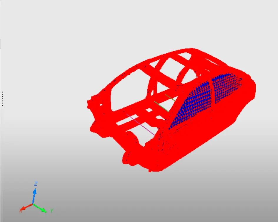
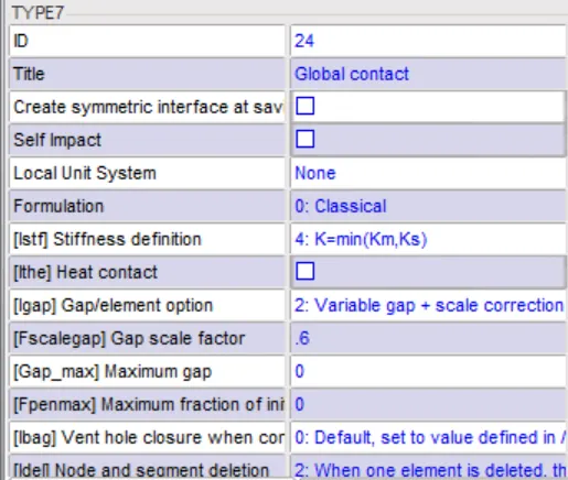
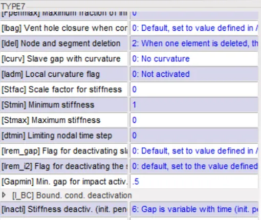
Fig: Contact Definition
4.Go into quality tab in Hypercrash and check for intersections and penetrations in the model. If intersections exist then manually, move out the nodes by translation. The initial penetrations are usually taken care of by the INACTI=6 contact definition setting.
5.Check for free parts in the model by going into the quality tab and checking the connections. It is found that three parts are free. By manually, inspecting the model rigid body connections are made in between the free parts to create a complete set of connected parts.
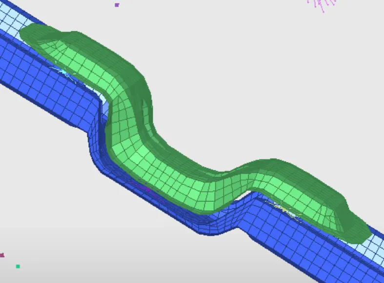
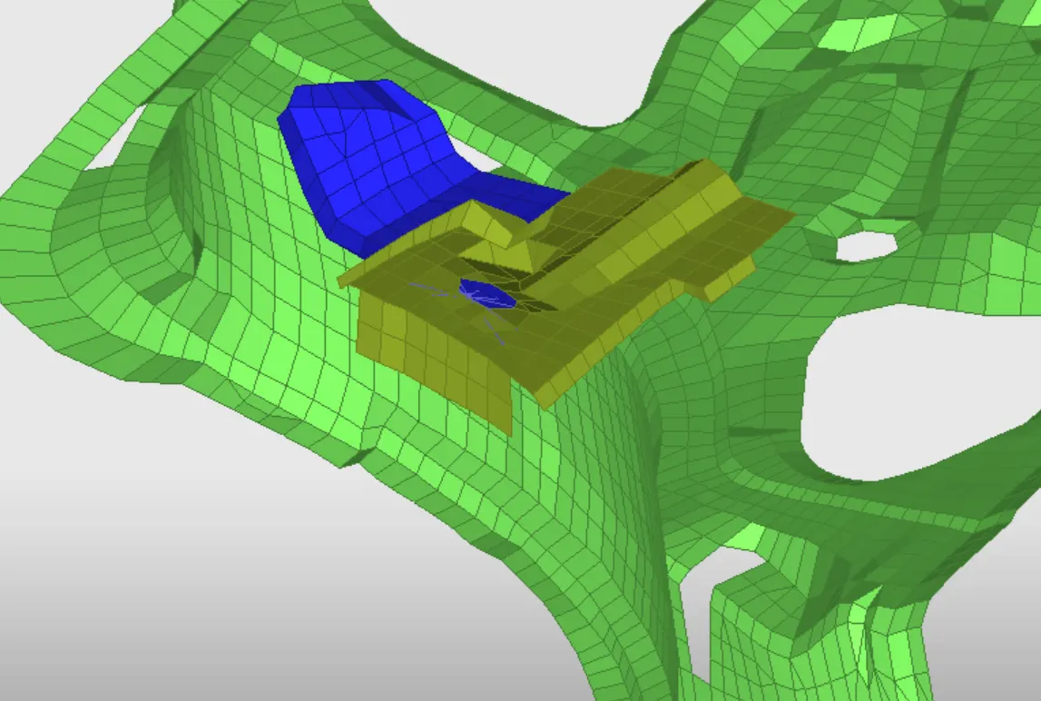
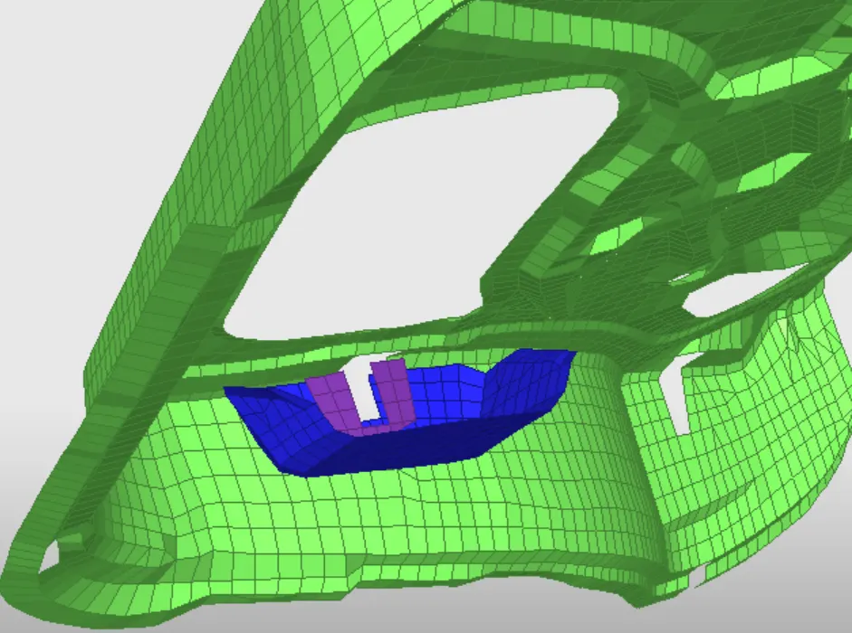
Fig: Rigid body connections
6. Create a rigid barrier (Cylindrical type).Appropriate coordinates are given for defining the cylinder axis and the pole diameter is set to 256mm with slave search distance 600mm.
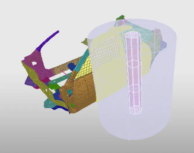
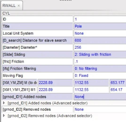
Fig: RWALL Definition
7. The target mass of the model is approximately 700kg. The mass initially provided was 188kg approximately. In Hypercrash-> mass->balancing-> check for the COG and the mass of the model. The COG has to be shifted to the center rail behind the driver’s seat. This can be achieved by adding mass (type 1 mass evenly distributed on the nodes). By intuition, mass of 200 kg for both passenger seats and 75kg for a single driver is given at the appropriate places. Also, mass of approximately 70 kg is given on the rear bumper to account for the luggage in the luggage cabin.
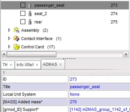
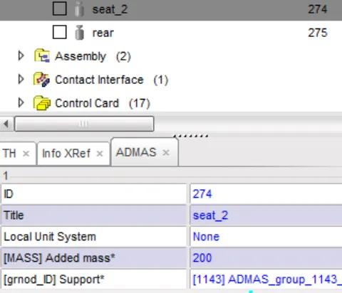
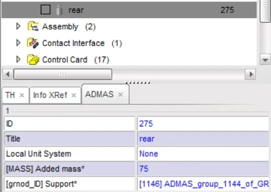
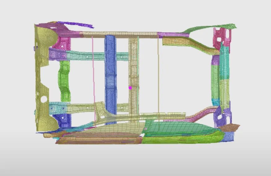
Fig: Mass addition and COM
8. In Hypercrash->load case-> INIVEL. Initial velocity is provided to the entire model by picking the entire model from the graphics. An initial velocity of 35 mph (15.6464 mm/ms) is given as translational y-axis velocity.
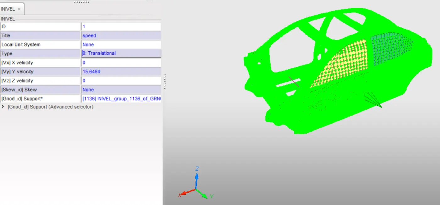
Fig: Initial velocity
9.In Hypercrash->data history-> set nodal, elemental time steps. The time steps given were 0.5 microseconds (0.0005 ms). A scale factor of 0.67 for nodal time step and 0.9 for elemental time step.
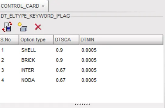
Fig: Time step Definition
10. The end time is set to 80ms.
Output requests
1.Sections were created at the two cross rails in the model. Plane sections were created by choosing the part, and then by picking the nodes in appropriate manner to create the section plane. Then systems (movable frames) were defined by appropriately picking the nodes on the same places where sections were desired. The sections were then assigned to the corresponding frames. A total of 2 sections were created. Time history outputs of the sections was included by turning the data history option of the sections to YES.
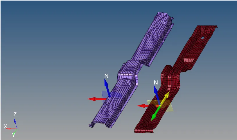
Fig: Cross rails sections
2.Side intrusions had to be measured at three locations fuel tank, side intrusion at the passenger door and at B-pillar bottom. This is done by creating three 1D elements parts (spring) and spring property (low stiffness and low target mass) was created and assigned to the parts.
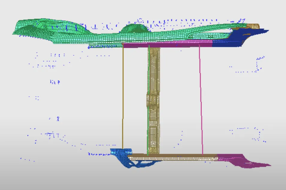
Fig: Springs for measuring side intrusions
3.Peak velocity of the inner node of the passenger door is selected and TH NODE card is created and assigned to the node. The nodal displacement, velocity, accelerations are recorded when variable definition is set to DEF.
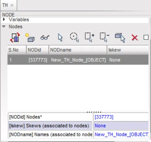
Fig: Node selection for peak velocity measurement
Quality check
1.In Hypermesh->tools->penetration check, check for penetrations,intersections and debug them manually. In Hypercrash->quality->check connectivity, check for connectivity of parts.
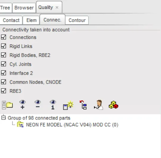
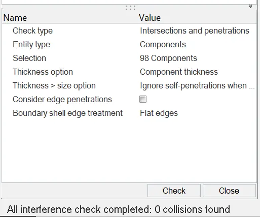
Fig: Connectivity, Penetration and Intersections check
2. Run the model checker, before starting to solve and check for errors and warnings. Debug them manually.
3. The model can be saved and imported to radioss for solving.
RESULTS
Energy Balance
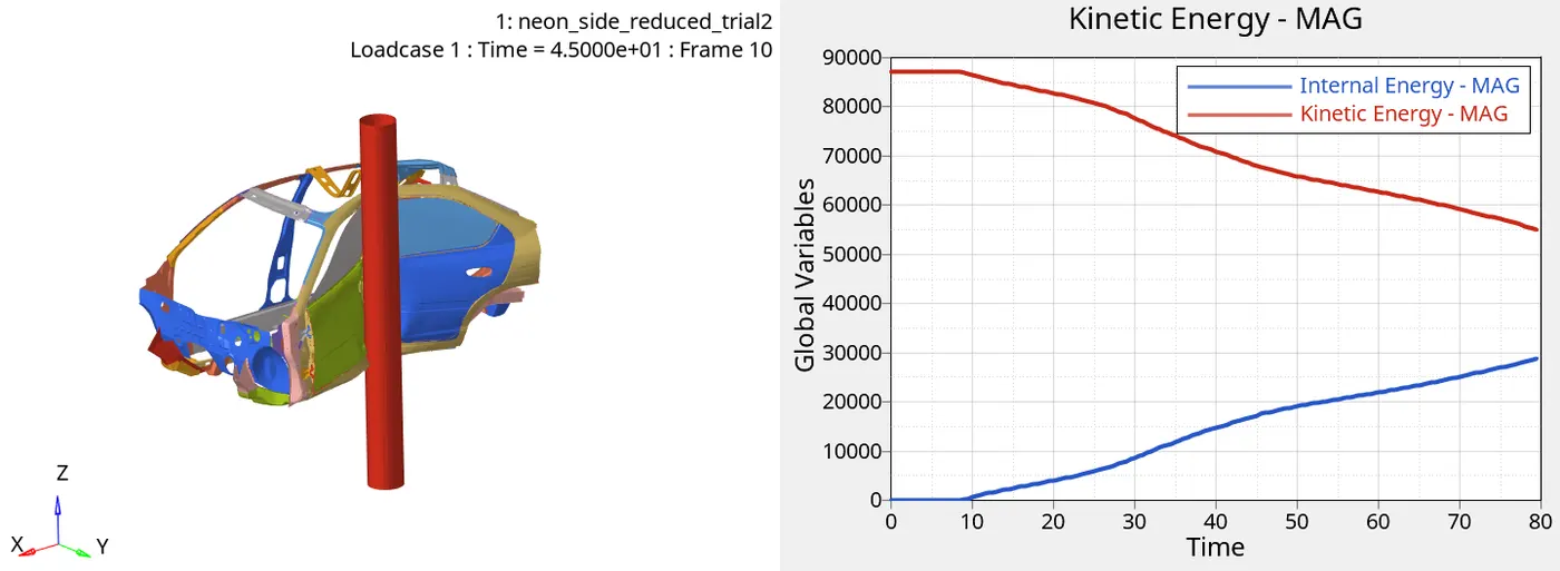
Fig: Energy graph
It is observed that kinetic energy decreases gradually after 8ms, this decrease is transformed in to an equivalent increase of internal energy. Internal energy too starts increasing after approximately 8ms, as soon as the crash starts and deformation begins.
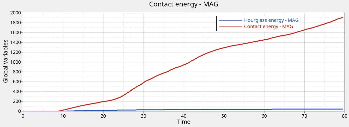
Fig: Contact and Hourglass energy
The percentage of maximum contact energy obtain during the crash is about 1900J which is 3.45 percent of the kinetic energy at the same time step. While maximum hourglass energy obtained is 50J at the end of the simulation.Thus, keeping the energy error under control.
RWALL Forces
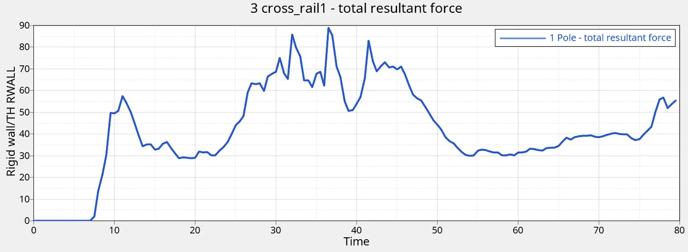
Fig: RWALL Forces
RWALL forces is zero for about 8ms before the start of the crash. Peak RWALL force of 90kN is reached in 37.5 ms and this force is transmitted through the cross rails to prevent shock to the passenger. Thus, it is observed that the design of the cage is very important in terms of the transmission of forces in a side crash and consequently passenger safety.
Section Forces
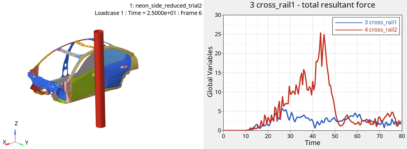
Fig: Section forces across cross rails
It is seen that the force distribution across the two cross rails is not the same. While cross rail-1 shows a peak force of approximately 6kN the other cross rail shows a peak force of about 26kN. It is also observed that the peak forces are achieved at different times for the two cross rails. This difference in peak forces and the time in achieving them is due to the positioning of pole. It can be observed from the simulation that cross rail-2 under the B-pillar experiences greater peak force as it is in direct alignment to the pole as compared to cross rail-1. Another observation from the graph is that although the cross rails are built for the efficient transmission of RWALL forces, a significant amount of the RWALL force still does not get transmitted through the rails. It can be concluded that, a side crash is more fatal than a frontal crash for a passenger.
Intrusions
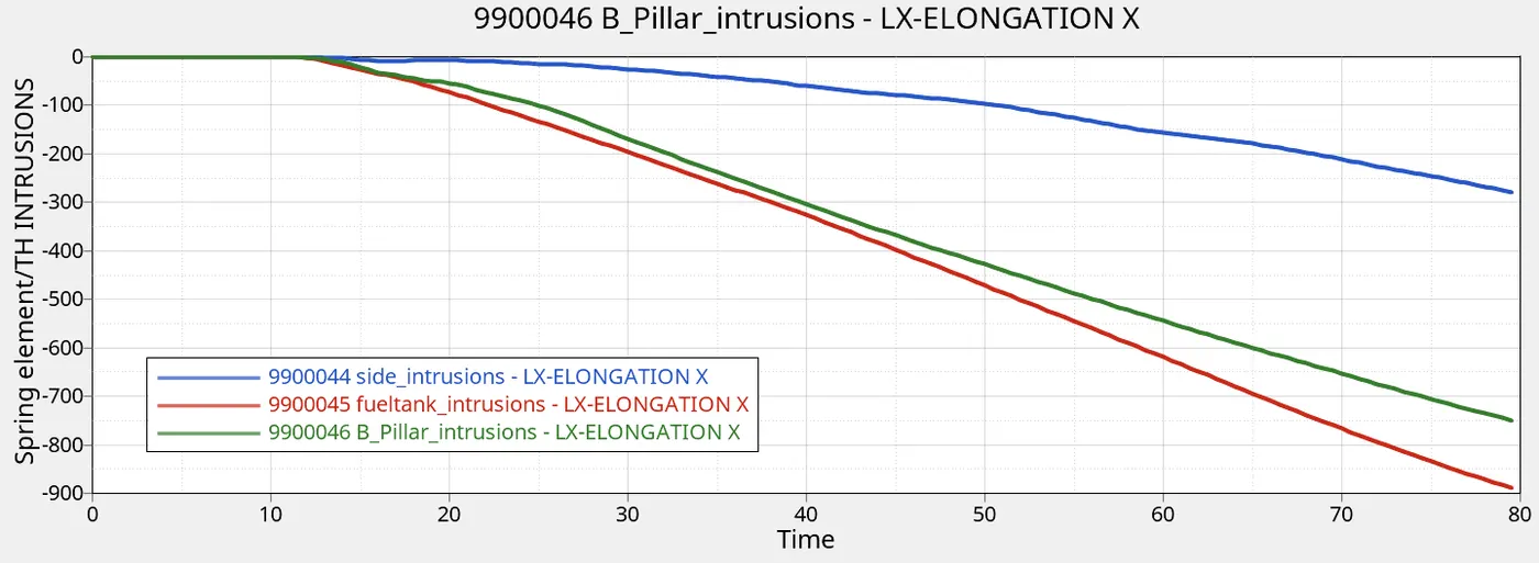
Fig: Side Intrusions
Intrusions at three locations were recorded. These involved side intrusion at the passenger cabin, fuel tank intrusion and B-pillar intrusion. It was observed that maximum intrusion occurs at the fuel tank (approximately 900 mm), and least at passenger side (approximately 300mm). While B-pillar experienced an intrusion of about 750mm. Thus, it can be concluded that passenger cabin is relatively safe while greater deformation occurs elsewhere.
Peak velocity
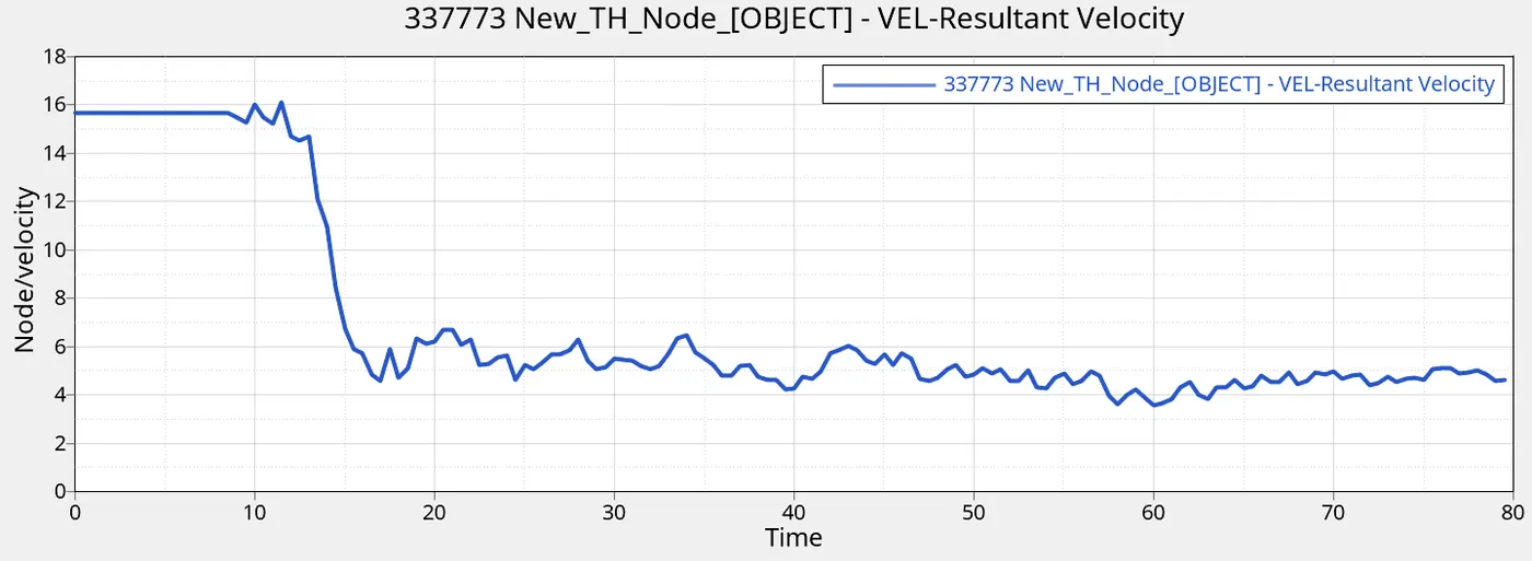
Fig: Peak velocity
Peak velocity of the node at the inner side of the passenger door was measured. Initially, just before the crash the velocity is equal to the initial velocity defined (15.6464 mm/ms) and it peaks to 16 mm/ms as soon as crash occurs. It then decreases over time.
Mass balance
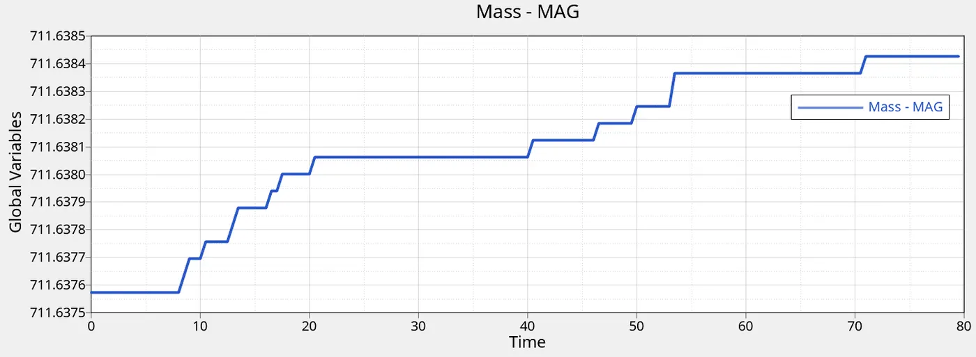
Fig: Mass error
As seen previously, the initial mass of the system was 711.607 kg. There is a small percentage increase (0.00464 %) by the end if the simulation. Final mass at the end of simulation is 711.64 kg. This is attributed to the constant time step (CST) algorithm used for time step control. Deformation of the elements decreases the critical length of the element, which in turn reduces the time step below the critical time step. To control the time step, the speed of the elastic wave is reduced by increasing the density by adding mass.
CONCLUSION
Thus, through the project I learned about the setup of the side crash on preprocessing tools such as Hypermesh and Hypercrash. Understood, the concept of contact modelling, creating load cases, time step control and generating output requests such as section time history plots, nodal velocity plots, intrusions etc. Finally, learnt how to debug different kinds of errors in a case. Various crashworthiness parameters were also understood, to interpret the results effectively.