Side Crash Analysis of Dodge Neon BIW - Using HyperMesh RADIOSS
Objective: To Perform Side Crash Analysis on Dodge Neon BIW Using Test Protocols Of FMVSS 214 Standards.
FMVSS 214 regulation:
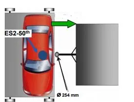
A 254mm diameter pole impact on a 90° oriented car, traveling at 35km/h, also called “oblique pole test”
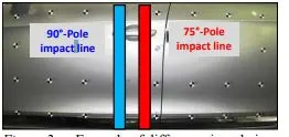
Impact pole places such that the impact line is aligned to the center of gravity of the car.
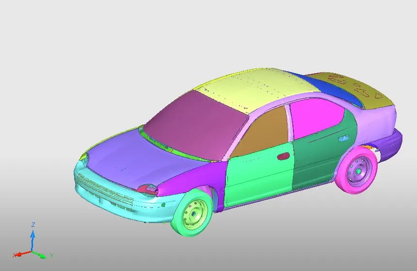
Full Car Model
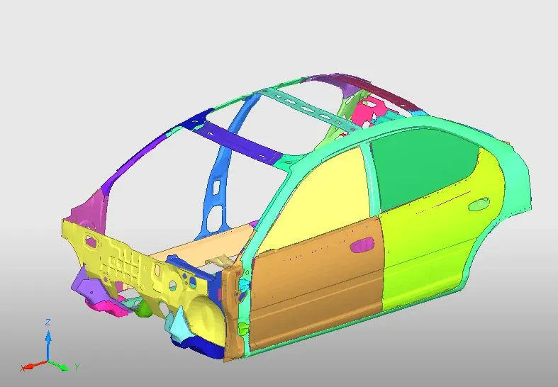
Reduce model
Unit System used throughout the simulation is Length (mm), Time(ms),Mass(Kg),Force(KN), Pressure(Gpa),Velocity(mm/ms) ,Density(M Kg/L) ,Energy(J)
Contact Interface
The Self Contact is created for the car model using Type 7
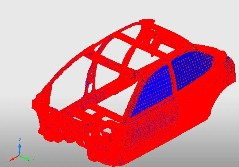
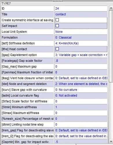
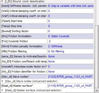
Igap(Determines how the size of the gap is calculated): 3 Variable gap + gap scale correction of the computed gap + size of the mesh is taken into account to avoid initial penetrations during self-contact.
Fscale_gap(Gap scale factor) : 0.8
Gapmin(Minimum gap for activation of the interface ): 0.5
Inacti(Action to take if initial penetrations exist): 6 Gap is variable with time but initial penetration is computed
Istf(Affects how the stiffness of the interface is calculated): 4 Kmin=(Km, Ks)
Iform(Friction formulation): 2 Stiffness
Stmin(Minimum stiffness to use in the interface): 1
Idel(What to do with slave nodes and master segments if an element fails (deleted) that they are attached to): 2 when a element is deleted, the corresponding segment is removed from the master side of the interface
Fric(coefficient of friction ): 0.2
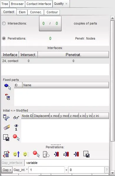
Penetration Check
Once the contact is defined we have to make sure there is no initial penetration and Intersection.
Connectivity Check
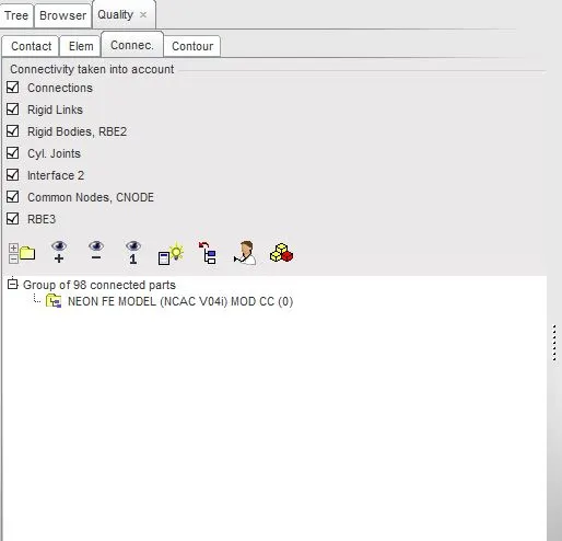
We have to make sure all parts are connected and there is no free floating part, if so that part alone will move separately in their own degree of freedom during the simulation
Floating part are connected using spring 2N element and P13_SPR _BEAM Properties is created for the spring element
Rigid wall Creation
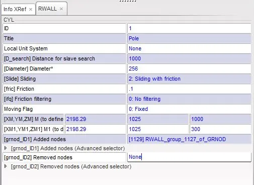
The rigid wall is the body is having high stiffness and we made the model to collide with the rigid wall. We here use a Cylindrical rigid wall.
We shouldn't move the Rigid wall very far away from the model. This is because if we do that the time taken for the car to run and reach the Pole is actually a wastage of cpu time. We dont want any results from that motion. So rigid walls should be only a little aside from the model.
Here we need a frictional rigid wall with sliding friction of 0.1
The diameter of the pole should be given as 250 mm.
Then the search distance for the slave nodes should be given as 1000
Mass Distribution
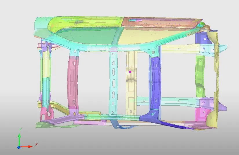
Then the centre of gravity of the model should be inline with the C.G of the full car, because in order to compare with the full model we should have the C.G in the same place. The location of the C.G is at the position when the line from the bottom of the driver seat meets with the central line. So in order to get the C.G at that place,
The total mass of the Full car model is 700kg, So we need to match these mass in our model and attain the C.G at Correct place by Distributing those mass in front and rear
Load Collector
Initial Velocity
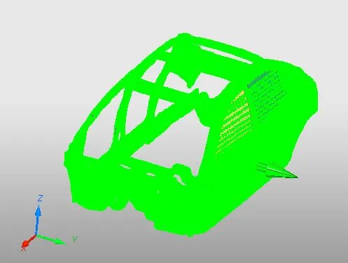
- 35mph is 15.6464mm/ms. So, a Load collector of initial velocity is created along the Global Y-axis with the friction of 0.1
- All the nodes of the car body are selected.
Cross Section
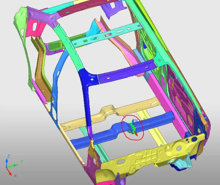
Cross Section is created on CH-CBN-SEAT-REINF-FT component to get the Sectional force of that component
Time History output
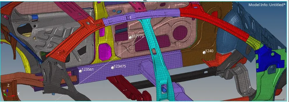
Time History Output of the following nodes are required to measure Intrusion at B pillar, hinge pillar and fuel tank region
123561 in Fuel tank region
123475 B pillar,
1240 Hinge
And time history output of node 337773 node in the side Door is also taken to measure the peak velocity of the door.
Model Check
- the constant nodal time step
- T_scal:0.67
- Time step: 0.5 micro sec
- Termination Time: 80ms.
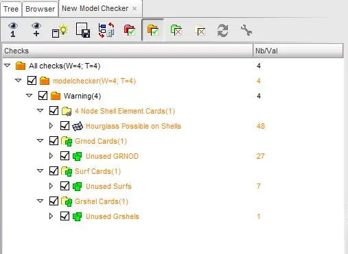
Before running the simulation is better to do the model checker and make sure there is no error in the simulation
.Out file

|
Number of Cycle |
ELAPSED TIME |
Energy Error |
Mass Error |
|
80001 |
7856.56 s |
-0.8% |
0.7964E-02 |
The energy error is -0.8% which is acceptable and mass error gradually increases but didn't exceed more than 5%, So the Result is acceptable for this Simulation.
Results
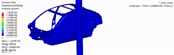
Displacement
Max Displacement: 1427mm
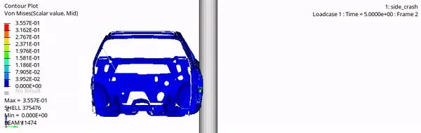
Von Mises Stress
Max Stress: 0.355GPa
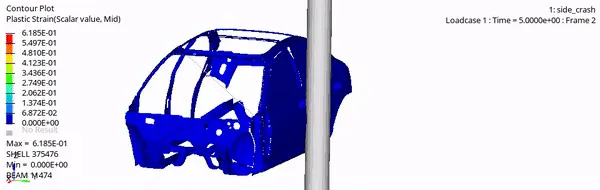
Plastic Strain
Max Plastic Strain: 0.6185
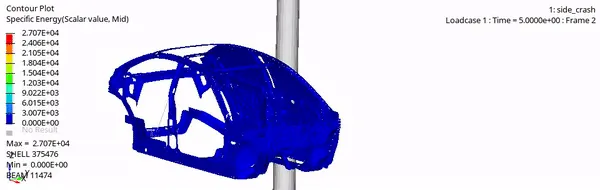
Specific Energy
Max Specific Energy:2707J
Graphs
Energy Graph
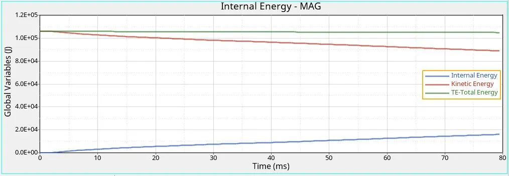
Kinetic Energy is high at the start because of the initial velocity applied to the car but it keeps on reducing due to the collision on the rigid wall which is converted into internal energy
Internal energy at the starting of the simulation is less because of higher kinetic energy and once the car impact on the wall the internal energy slowly increases
The Total energy should be equal to the external work done but this is simulation their slight loss in total energy that’s because of contact energy
Cross Section Force
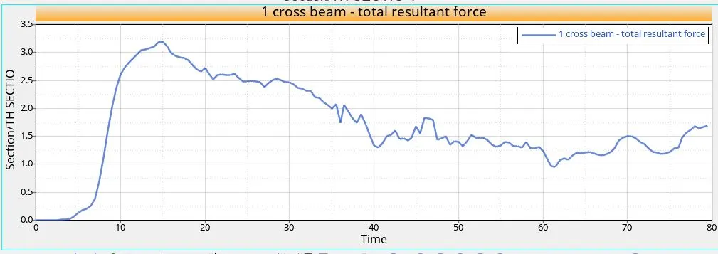
It take the First 5ms to impact the pole that's why the force starts from 5mms and it gradually increases and reaches maximum and deformation starts and force also decreases.
The maximum resultant force of the cross member is recorded at 15ms with 3.25KN. Cross-member being the thin member of the two has deformed more.
Intrusion
Fuel Tank
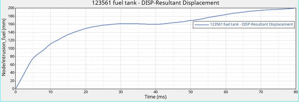
The Displacement curve slowly increases till 30ms and stays constants till 47ms its because the component required addition force for the deformation once it reaches the nest lower yield point of materials
The Intrusion of Flue Tank is found to be 200mm
Methods to reduce the Intrusion:
Other regions had beams connecting the pillars across both sides. these beams carry the seat of the car. Crossbeams covering the fuel tank region would probably reduce fuel tank intrusion. If seats were arranged, the intrusion levels could decrease comparatively.
C pillar component and structural strengthening could reduce intrusion over fuel tank region
The intrusion at the Fuel tank region can be reduced by increasing the strength of the rocker by using material of good yield strength or increase the thickness of the rocker.
B-Pillar
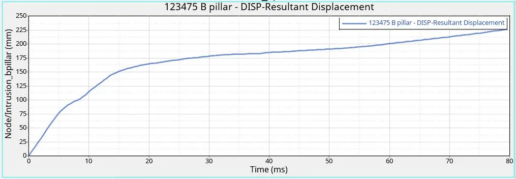
The Displacement keeps increasing gradually till 20ms once the b-Pillar Hits the pole it can't go further that's the rate of change of displacement after 20ms as reduced .
The Intrusion of B-Pillar is found to be 240 mm
Hinge
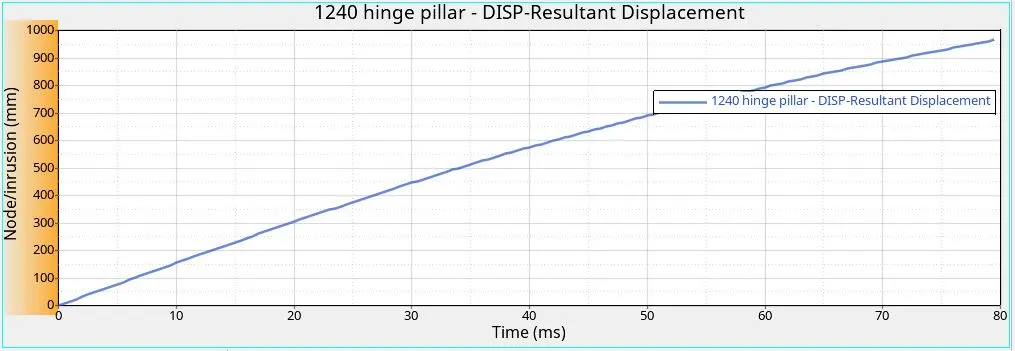
Displacement constantly increasing throughout the simulation
The displacement of the hinge is pretty higher compared to the other because Hinge, A-pillar, and fender are still moving beyond the pole but the B-pillar impact on the pole and can't move any further.
The Intrusion of Hinge is found to be 1000mm
Peak Velocity of Door
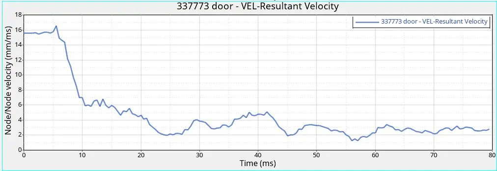
Due to the initial velocity applied to the car at starting the graph starts at 15mm/ms and almost stays constant until the impact.
The curve starts to decreases due to the impact.
The spikes are due to the resistive force of components material sue to the impact.
The peak Velocity of door after the impact is: 17mm/ms
Conclusion :
Side Crash Analysis on Neon BIW is performed in FMVSS 214 Regulation
Since the Centre of gravity of the car and the mass addition plays a very critical role We Matched the CG of a full car model to Get Proper results.
The intrusion of the B-pillar Fuel Tank region and the hinge is been measured
B pillar plays a major role in reducing the side-impact and protecting the passengers from its effect, it redirects the force to roof and the cross beams so that the shock is reduced and the passengers are protected.
And Side Impact bars in the door helps to reduce the intrusion in B-pillar and Fuel tank region
Peak Velocity of Door Starts at 15mm/ms but we can't take that as Peak velocity Because that's is applied velocity of car at Starting , so the Peak Velocity can be considered only after the impact
Peak Velocity of the Door is 17mm/ms
File: https://drive.google.com/file/d/1-F_vbAkZ9T84l8Ox2BXWrq7KLBIBP4sV/view?usp=sharing