Assignment 7
AIM:
-To run a side crash test simulation for the given model of side beam of car.
Solution:
1)To check for the unit systems:
-Initailly we will have to check the units ,here in our case we can make use of [kg mm ms].This units can be edited or checked by clicking on neon_side_0000.rad in the note pad file.
2)To create appropriate interface,friction of 0.2 and recommended parameters:
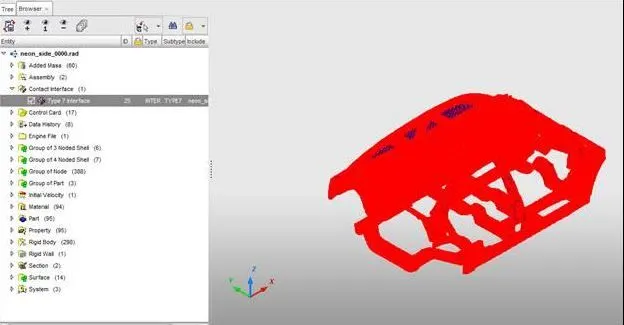
-Here we have delete those default available interface of the original models and we now create a new interface by new name Type 7 interface.
-Recomended properties are given as follows: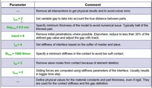
-Here we can create a type 7 interface either in hyprmesh or in hypercrash,in our case we have created it in hypercrash file.
-To create in hypercrash we need to select the load case from top menu>contact inteface>right click create new>muti usage (type 7),now give the appropriate value and friction as 0.2.
3)To make sure of no penetration or intersection:
-Now before running the model we have to make sure that there is no penetration or intersection between two parts of the body.
-Now to check for penetration and intersection in hypercrash go to load case in upper tab menu>conatct interface>select contact type 7>click on check penotration for selected objects.[Here we select the entire car model (shift+left mouse button)]
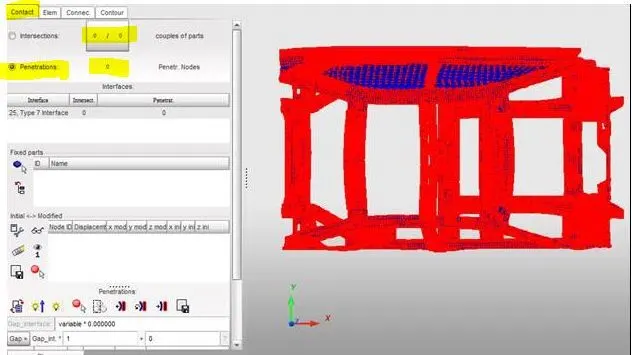
-In our case as we donot see any penetration and intersection we are now ready to run the analysis.In case if we see and errors or warnings staiting penetration or intersection we can rectify it by using auto fix tool or manual method.And also there is no issues with the rigid body.
4)To create a rigid wall with friction of 0.2:
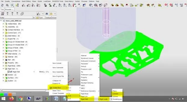
-Now here we will have to create a rigid wall in the given model with a friction of 0.1.Here in our case we create a rigid wall in hypercrash by using the option (Right click>create new>M-R>rigid wall>cylinder.[Here we have selected cylinder because the impact will be on side wall beam which is cylinderical in symmetry].
-Here we have to set the parameter as per hypercrash setting for node D,search as 1000mm,dia 300mm and friction as 01.
5)Comparing the weight wiith full-scale model for wieght balancing:
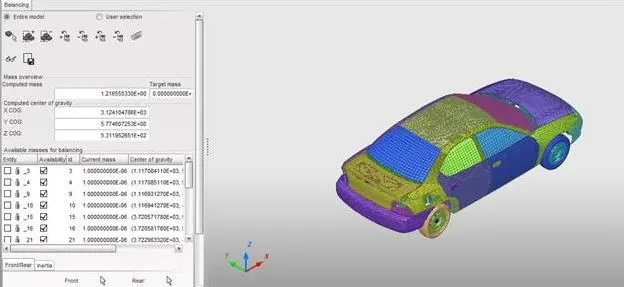
-Here the weight of the full car model is around 1216.55 kg as shown below:
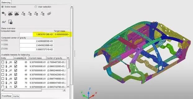
-The weight of the model which use for analysis is around 166.30 kg
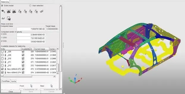
-Here we need to balance the weight to reach around 700kg based on this we have compute the mass carefully so that we will get the center of gravity near to driver seat location line.
-The added mass at the bottom rail =333.70 kg and to back rail =200 kg and suming the above two mass we will get a total upto 700kg and is shown as below:
-The COG of the model is shown as below and is representd in a pink dot;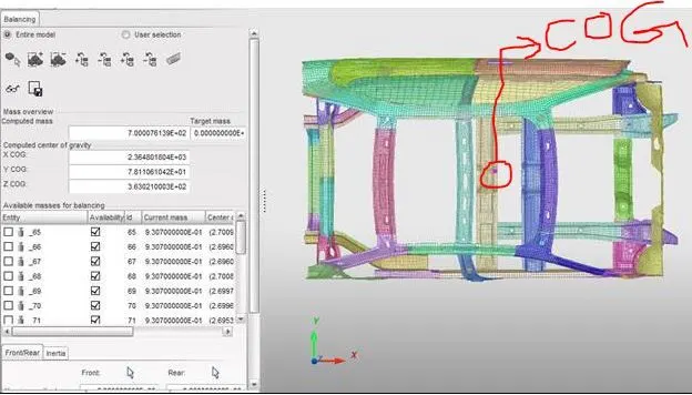
6)To apply initial velocity of 35mph:
-Here we will have to first convert 35mph to mm/ms as we follow the units in [kg mm ms].After converting we get a value around 15.65 mm/ms.
-To apply initial velocity we need to follow the following option (hypercrash) go to load case>initail velocity>select the whole model and apply in X-dierection as 15.65 mm/ms.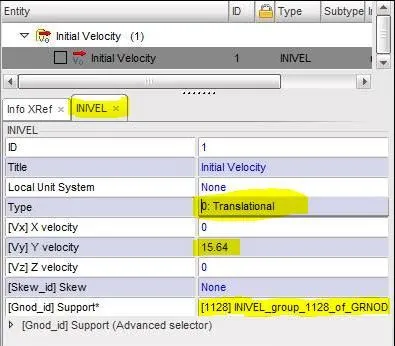
7)Use model checker to ensure good quality:
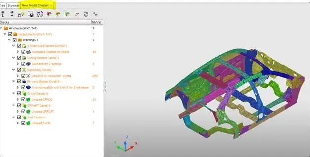
-Before running the simulation we need to check build quality of the model by using the option (hypercrash) go to quality>model checker>run.Here we will definitely will encounter some error and warning we need to find it out and auto correct the tool or manual correction is required.
Output requests:
- Sectional force in the cross member.
- Intrusion at B pillar,hinge pillar and fuel tank region.Provide recommendation on what can help to reduce Fuel tank intrusion.
- Peak velocity of inner node of the door.
-Now to get the forces in the above section we need to create the section at those places.for that go to Data history>section>select segments>now select three nodes to create a section.
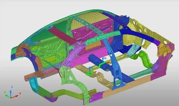
-Now we run the simulation and the out cycle energy mass error are obtained as below:
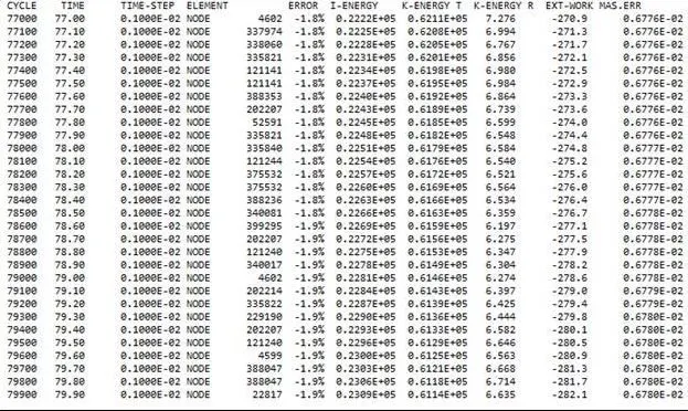
-So from the above output of the model we can see that energy error is -1.9% and mass error is around 0.6780E-02 and this value are under acceptable range.
-Graph plotting:
1) sectional force in the first cross member:
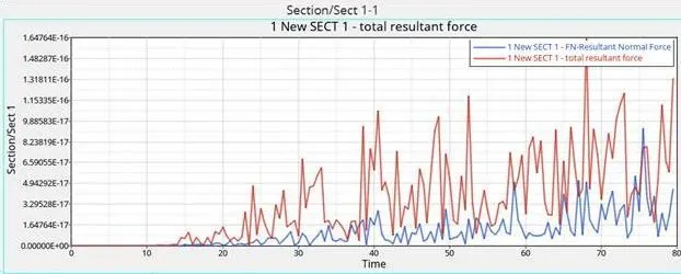
-From the graph we can see that maximum force is observed around 70 ms step as 1.48E-16KN where most of impact force is taken over section with respect to cross member.
2)Sectional force in the second cross member:
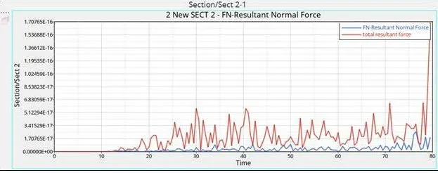
-Here the max force is observed around 80 ms with step time as 1.70E-16KN as we see most of the impact will be on section with respect to cross member.
3)Intrusions at B pillar ,hinge pillar and fuel tank region:
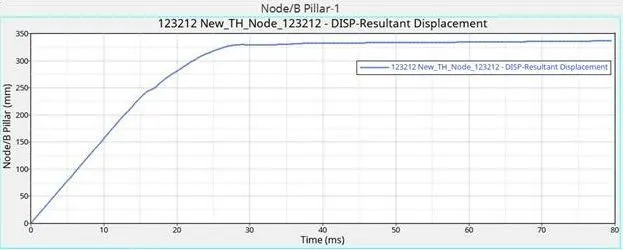
-The intrusions at B pillar with respect to local skew is around 336 mm.
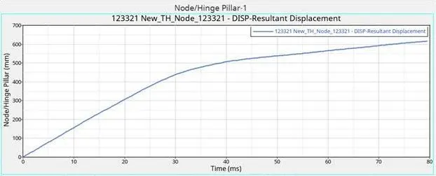
-The intrusions in hinge pillar is around 620 mm.
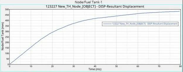
-The fuel tank region intrusion is around 480 mm which can be minimised by increasing the strenght in the cross member as well as in the C pillar.
4) Peak velocity of the inner node of the door:
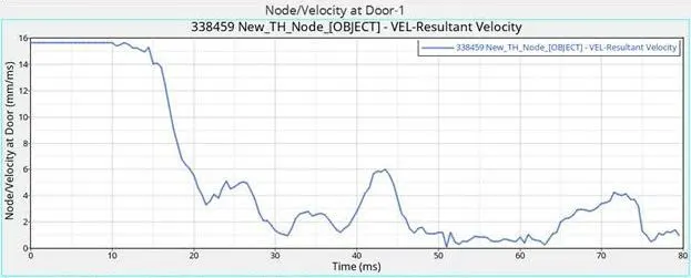
-The maximum peak velocity value observed in the graph is around 15.66 mm/ms.
5)Energy graph the model is as shown below:
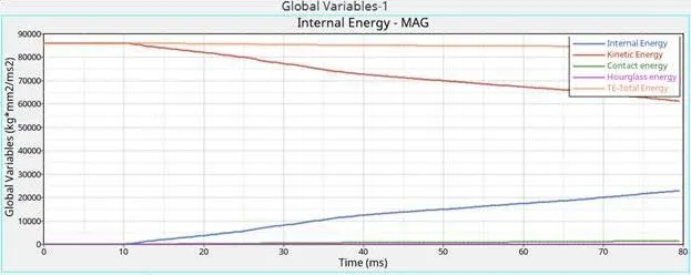
-The energy graph shows zero value of contact and hourglass energy,Here the maximum energy obtained is around 86160 (kgmm^2/ms^2) where we know that kinetic energy dicreases and internal energy increases.
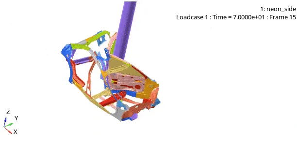
-The animation file of model is as shown below:
-Conclusion:
i)The section force in the cross member plays an important role in absorbing the max impact.
ii)The role of support members as B pillar,hinge pillar are important to keep less impact transmiting to interior part of the vehicles.
iii)The maximum velocity at the door is a major concern as the driver is near to the door.
iv) The position of COG of the vehicle plays an vital role in crashworthiness and maintaing it will depend on skills that an engineer inputs to it.
v)As we are using half model with added we can also make use of full model analysis so we get a realistic results.