Side Crash Analysis on Neon BIW using Radioss
Aim
- To make side crash setup on Neon model car biw assembly
- Study it's various components
- Understand conditions to be applied for side crash
- Simulate and obtain output results
- Analyse the results and conclude
Objective
Side Crash BIW
- Check unit system and either follow [Mg mm s] or [Kg mm ms].
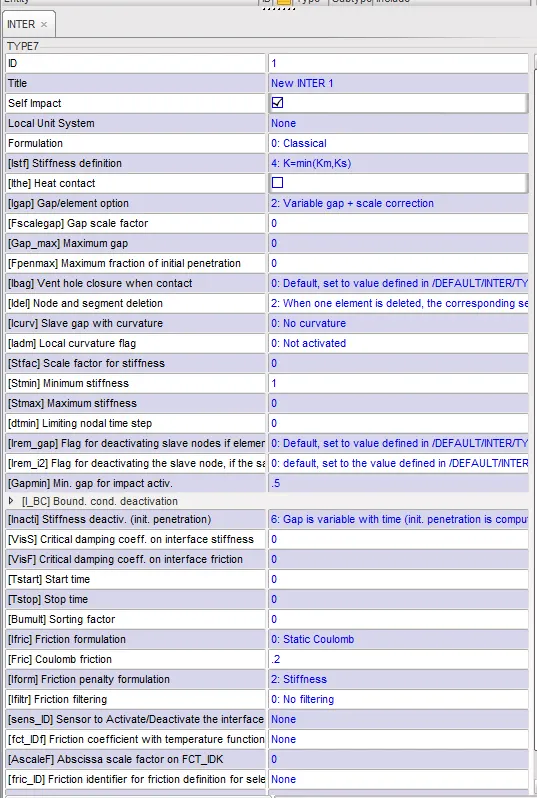
- Create appropriate interface ,friction 0.2 and recommended parameters.
- Make sure of no penetration and intersections.
- Create rigid wall with friction 0.1 as per referance model.
- Compare the model weight with the referance model and use added masses to reach target weight 700kg while getting CG about the required range.
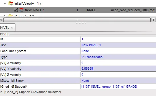
- Initial velocity as shown in picture.
- Use model checker to ensure good quality.
- Timestep :0.5 to 0.1 microseconds.
- Run 80ms.
Output requests:
- Sectional force in the cross member.
- Intrusion at B pillar,hinge pillar and fuel tank region.Provide recommendation on what can help to reduce Fuel tank intrusion.
- Peak velocity of inner node of the door.
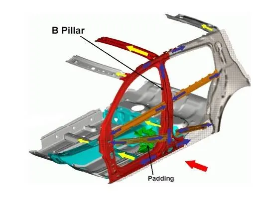
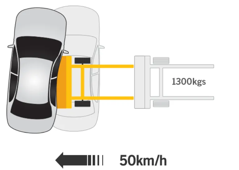
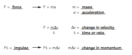
Physics of Side crash

Side Crash Analysis Setup
Unit system
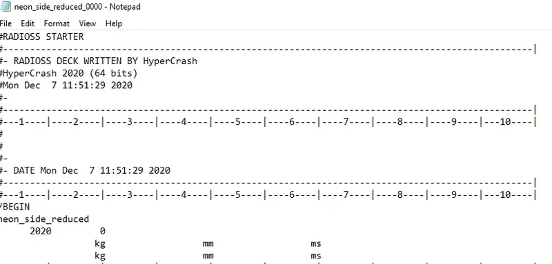
Type 7 Self Contact was applied with Recommended Properties
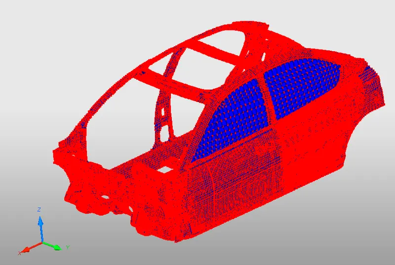
Intersections and Penetrations
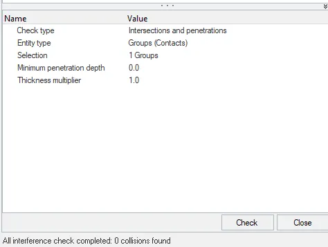
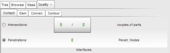
No Intersections and Penetrations were found
Mass Distribution
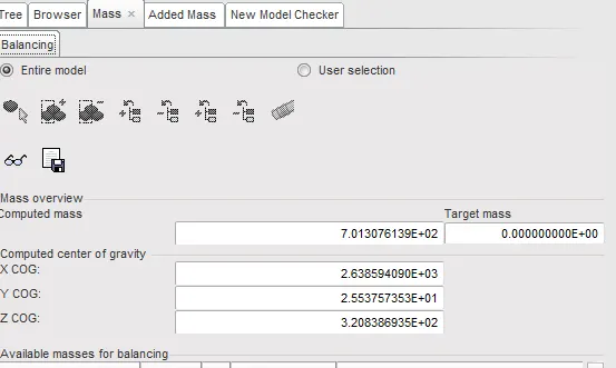
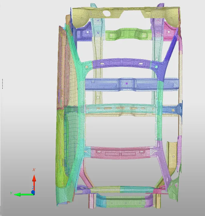
Overall mass was adjusted to 700kg with C.G at balance near gearbox and engine
Initial Velocity
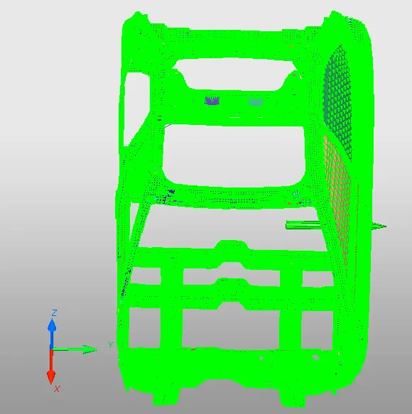
According to FMVSS standards Initial velocity of 8.9 mm/s was given
Rigid Wall
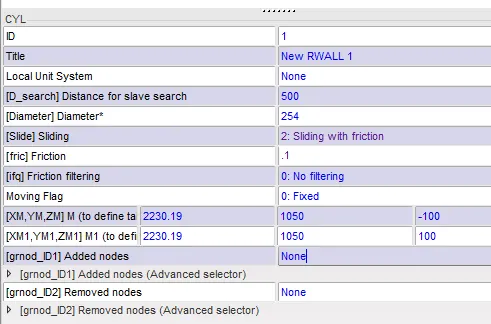
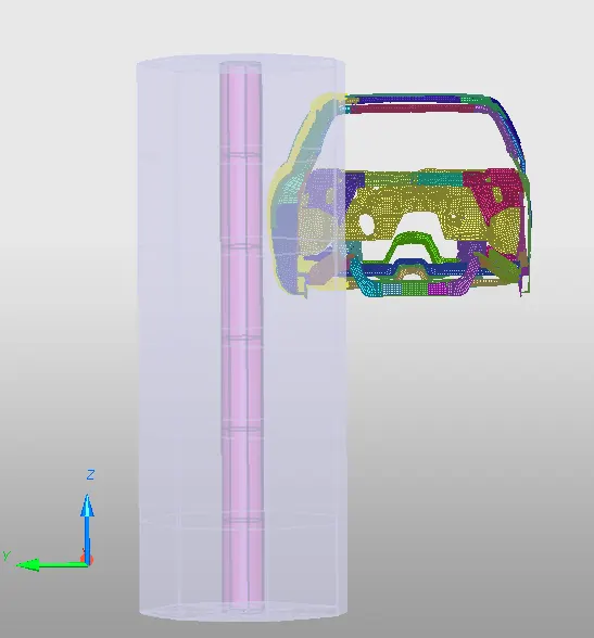
A cyclidrical wall with 254mm diameter and was given according to FMVSS standards
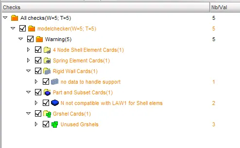
Model Checker
Timestep :0.5 to 0.1 microseconds
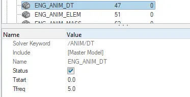
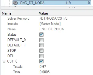
Time step was set to 05 mocro seconds
Sectional Forces on Crossbar Setup
To study sectional forces section was created with Frame/Skew as reference and TH card was created to read it
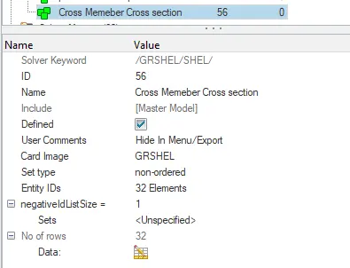
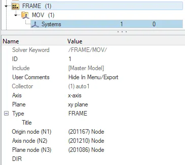
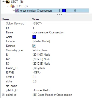
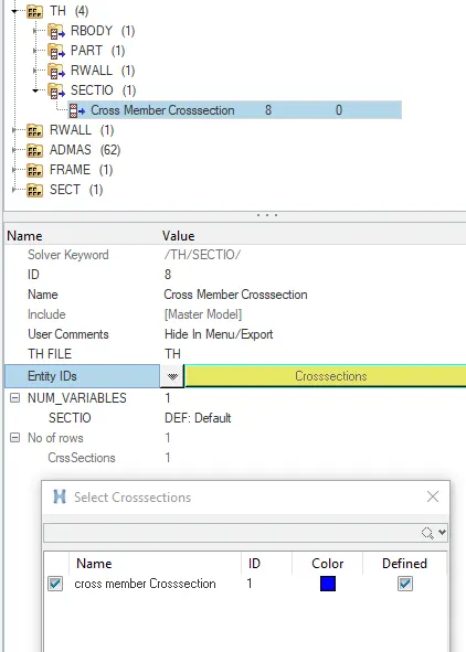
Sectional Forces on Crossbar
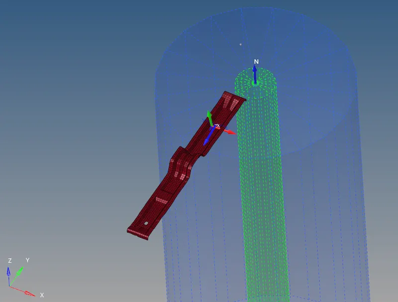
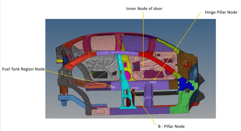
Skew created Oppsite to Hinge pillar node to find Intrusions
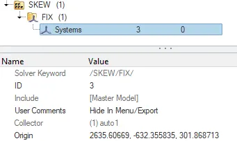
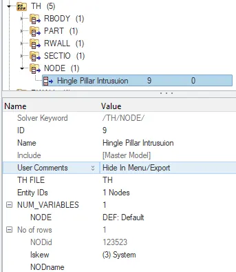
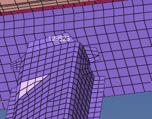
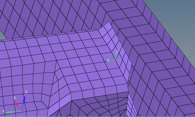
Creation of fixed Skew to find B - Pillar node Intrusions
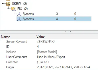
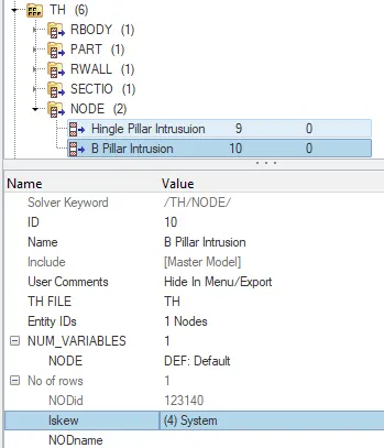
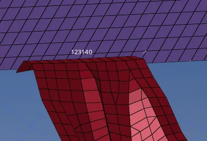
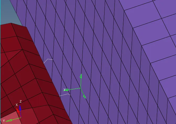
Creation of fixed Skew to find Fuel Tank Region node Intrusions
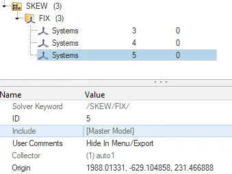
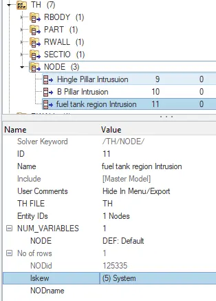
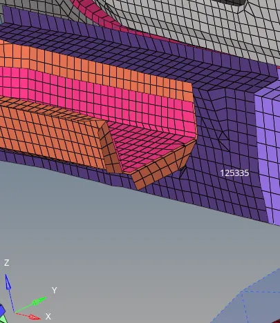
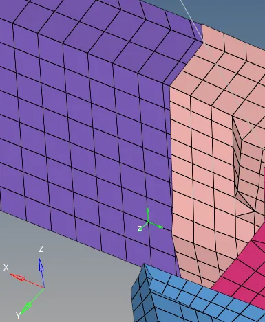
Opposite face skew- fixed is created
Post Processing
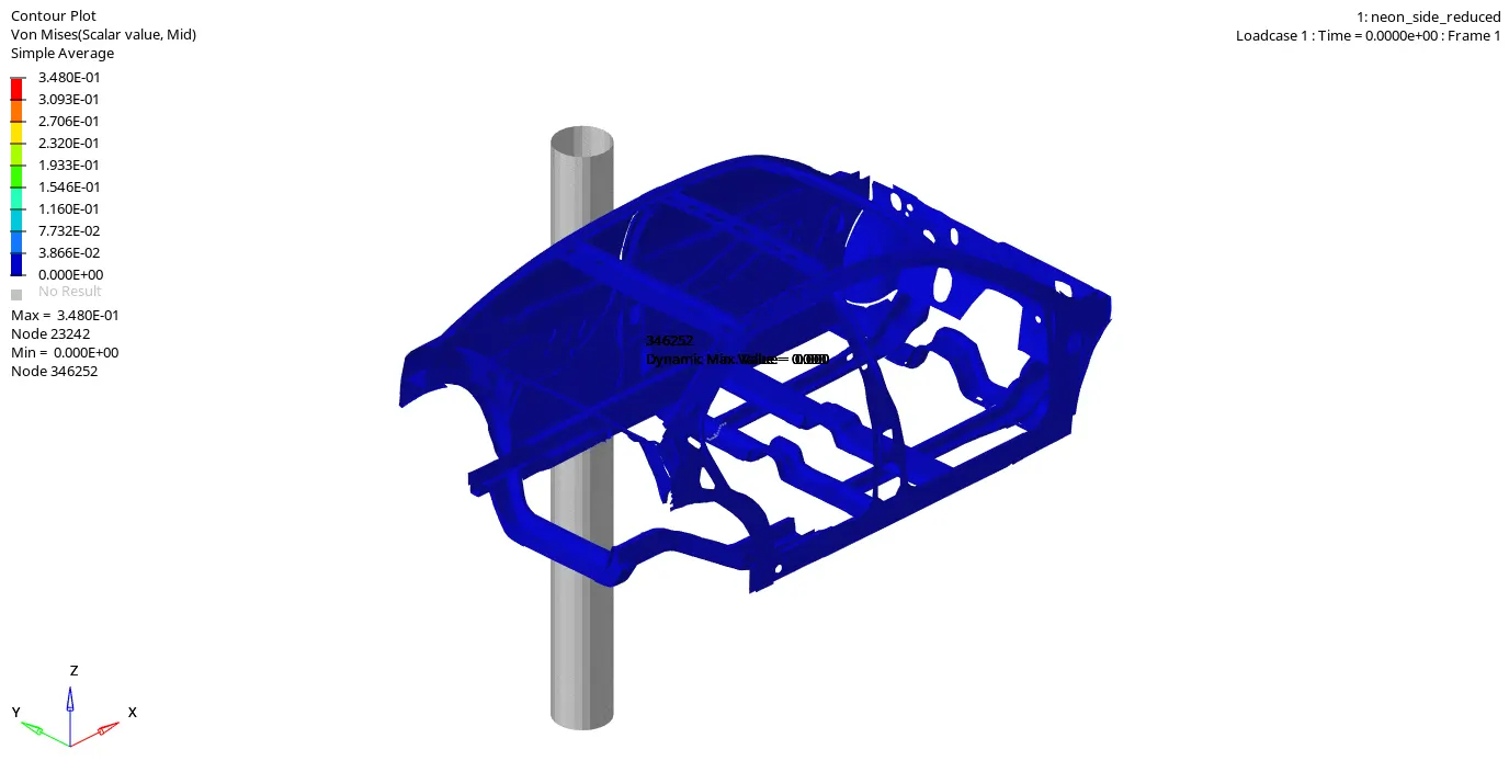
- Maximum Stress = 0.348N/mm^2
- Connectivity isssue can be seen in the rear portion of car which can be rectified using type 2 spring
Displacement
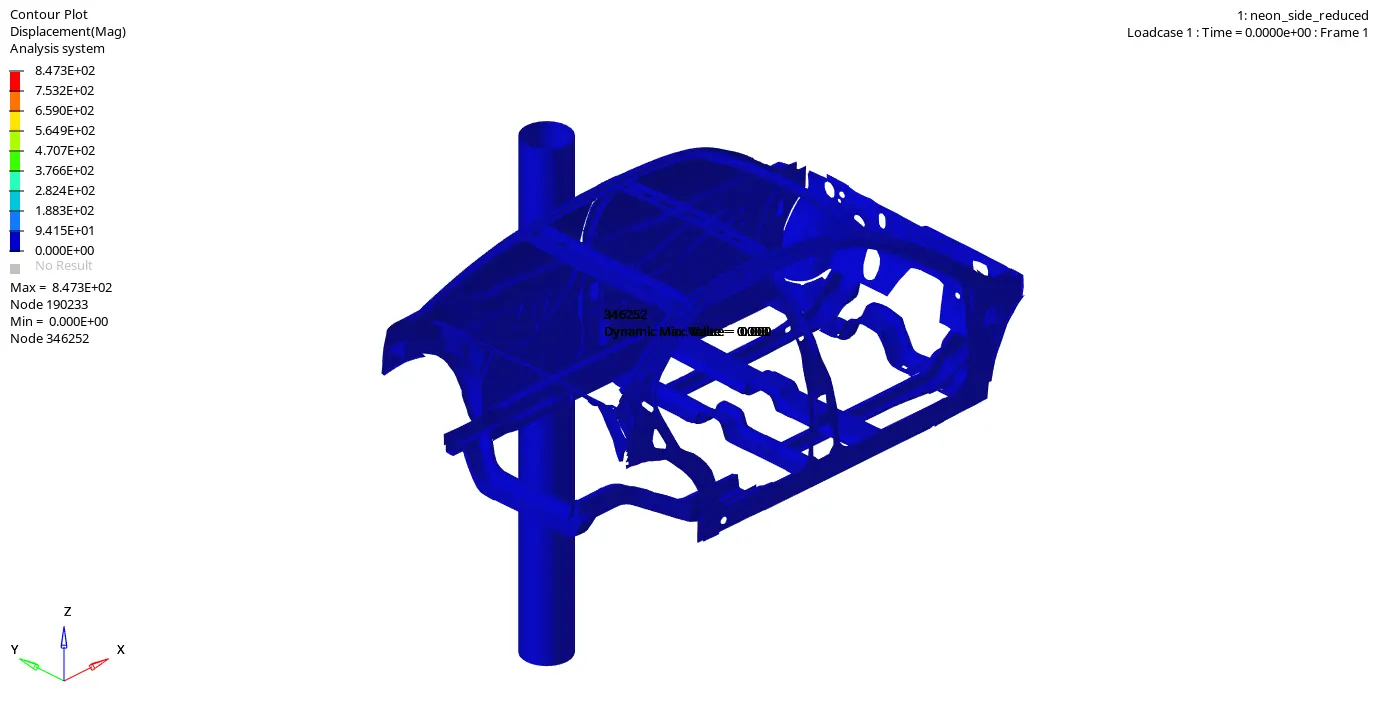
- Huge displacement is seen in Side Crash of about 847mm
- Displacement can be reduced by changing material properties
Energies
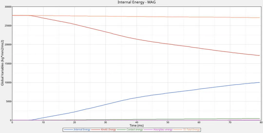
Inference
- At initial stage Internal Energy almost zero then it raises steadily after 7ms but Kinetic Energy his high from initial stage 2750 kg-mm^2/ms^2
- Hourglass Energy is zero Element formulation QEPH = 24 and other recommended shell element properties
- Contact energy is less as the interference of slave node in master segment was less due to given contact interface (Type 7)
- Total Energy is sum of all Energies
Rigid wall forces
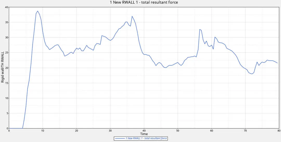
Inference
- The Resultant force is 37kN peak value at 8ms just after collision with B-Pillar
- After some time at 37ms it spiked slowly till 36.5kN and then reduced.
- At 75ms forces on rigid wall is gradually decreasing
- Variation in forces on rigid wall due to impact of different components on that come into contact based on D_Search value and material property.
Cross Member Cross sectional forces
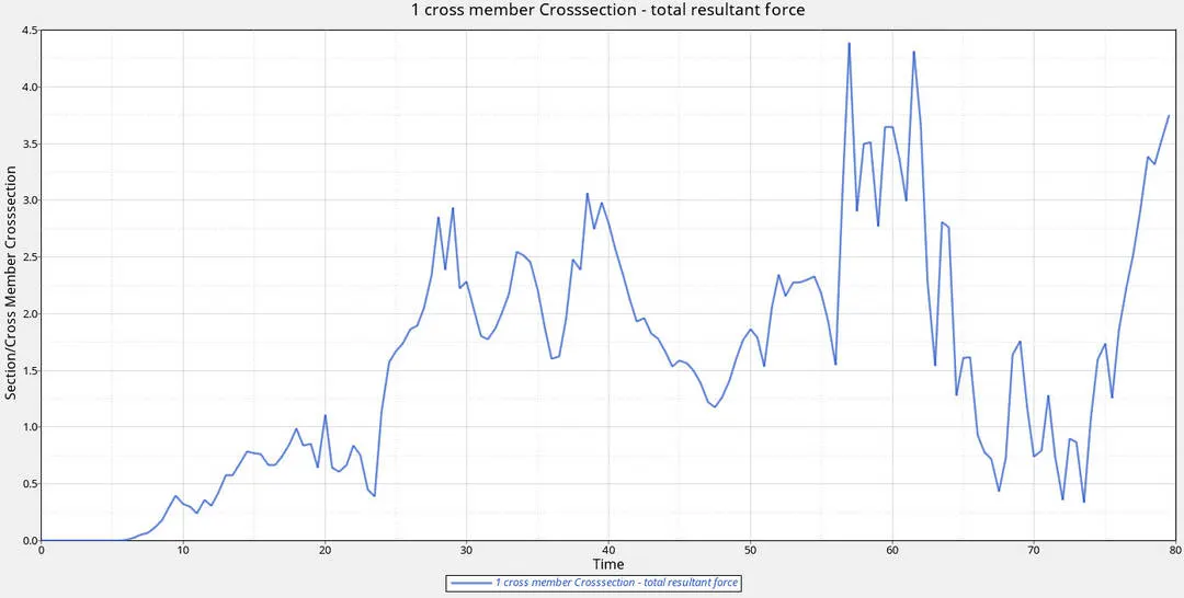
Inference
- Intially there is no force as the impact is taking place on B-Pillar
- After 7ms there is spike in resultant force on cross member
- Peak resultant force can be seen at 56ms of 4.3kN then at 62ms of 4.23kN later there was deformation in cross member then reduction
- Again there is increase in resultant force after 73ms which means there was deformation taking place and 80ms ms there was resultant force of 3.75kN
Hinge Pillar Node Intrusion
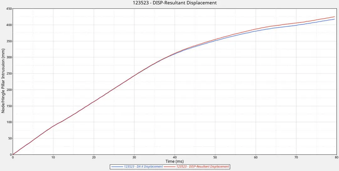
Inference
- As the time increases there is increase in displacement with respect to time
- Hinge pillar is connected to cross member
- Maximum displacement in hinge pillar can be seen at 80ms of 425mm
- Intrusion can be reduced using strong material with good elastic properties
B-Pillar Node Intrusion
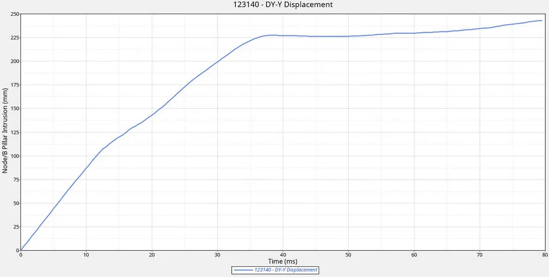
Inference
- As the time increases there is increase in displacement with respect to time till 35ms
- After 35ms the displacement is uniform there is no further intrusion
- Maximum intrusion of node can be seen at 40ms of 225mm to240mm till 80ms
- From 0ms to 34ms there was deformation; after that elastic range of material reached plastic range
Fuel Tank Region Node Intrusion
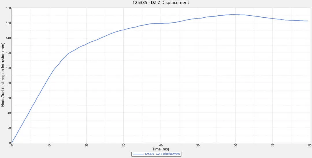
Inference
- Displacement increases gradually till 30ms after there is a spike at 50ms and reduction in dispalcement after 70ms
- Maximum displacement can be seen at 60ms of 170mm then reduced to 162mm at 80ms
- Intrusions near fuel tank region must be as less as possible
- Fuel tank region connects hinge pillar and B-Pillar
- Assemblies connecting fuel tank need to have good hardness, resilience and yeild strength
Peak Velocity of Inner Node of the door
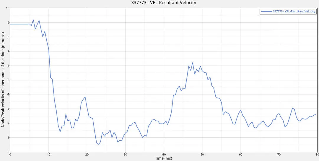
Inference
- As the node is near B- Pillar there was velocity initially 8.9mm/ms.
- Then there is drop in velocity at 12ms it was due to side pole impact in B-Pillar direction and resultant forces
- Again there is spike in velocity at 48ms of 6.2mm/ms
- Later the node displacement reduced to 3mm/ms

Results and Conclusion
- Setup of Side imapct was done according to FMVSS standards
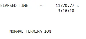
- The energy error is -1.8% which is acceptable and mass error gradually increases but didn't exceed more than 5%, So the Result is acceptable for this Simulation.
- B- Pillar is the first area of impact in Side crash, from B-Pillar it's transferred to cross member and roof members
- Centre of gravity and Load/mass distribution are important aspects to be taken into account and considered; based on which results of output can be derived.
- Cross members play vital role by diverging the impact on fuel tank
- As the impact is on B-Pillar the peak velocity near door has been reduced gradually.
- Shell element properties and Recommended properties for rigid wall, Contact Interface and Initial velocity play major role in determining the result.
References
https://web.iitd.ac.in/~achawla/course_pdfs/4.%20MEL736/11-Crash_Safety_practices.pdf
https://www.linkedin.com/pulse/body-white-biw-design-fundamentals-part1-mahm%C3%BCd-hosseinjani/
http://caxsol.com/services/cae-services/crash-simulation/
https://www.nhtsa.gov/sites/nhtsa.dot.gov/files/tp214p-01.pdf
https://link.springer.com/article/10.1007/s11071-018-4688-x
http://ffden-2.phys.uaf.edu/211_fall2002.web.dir/ben_townsend/PhysicsofCarCollisions.htm
https://www.scielo.br/scielo.php?script=sci_arttext&pid=S1679-78252019000800506
https://www.laserpablo.com/teacherresources/files/PhysicsofCarCrash.pdf
https://www.electrical4u.com/mechanical-properties-of-engineering-materials/