Side Pole Impact Analysis of NEON Doge Model in FMVSS Regulation
Side Pole Impact Analysis of NEON Dodge Model in FMVSS Regulation
Objective:
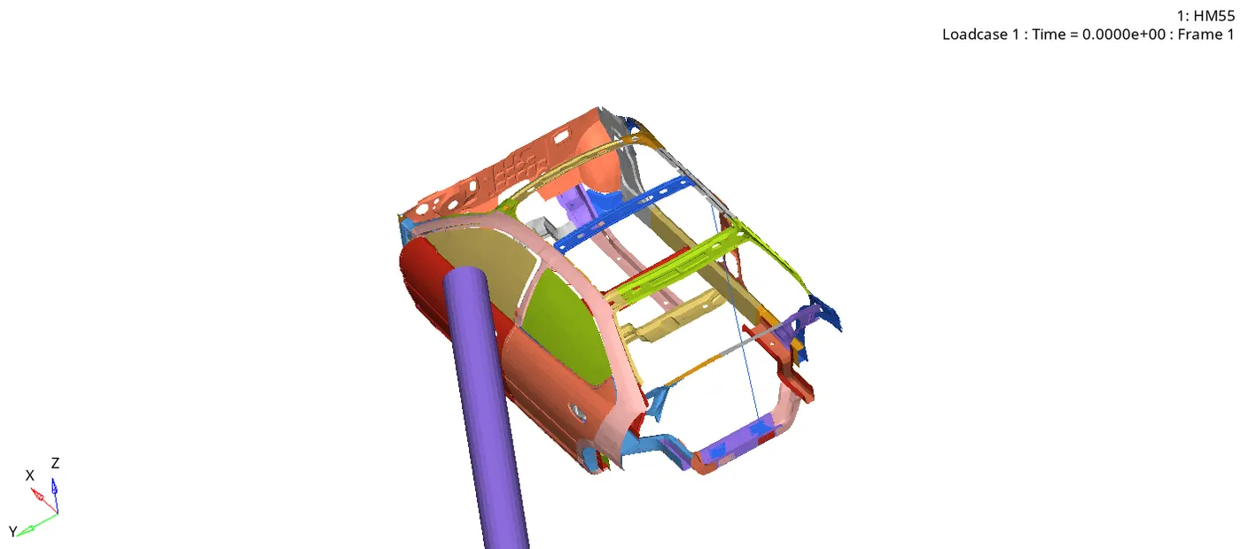
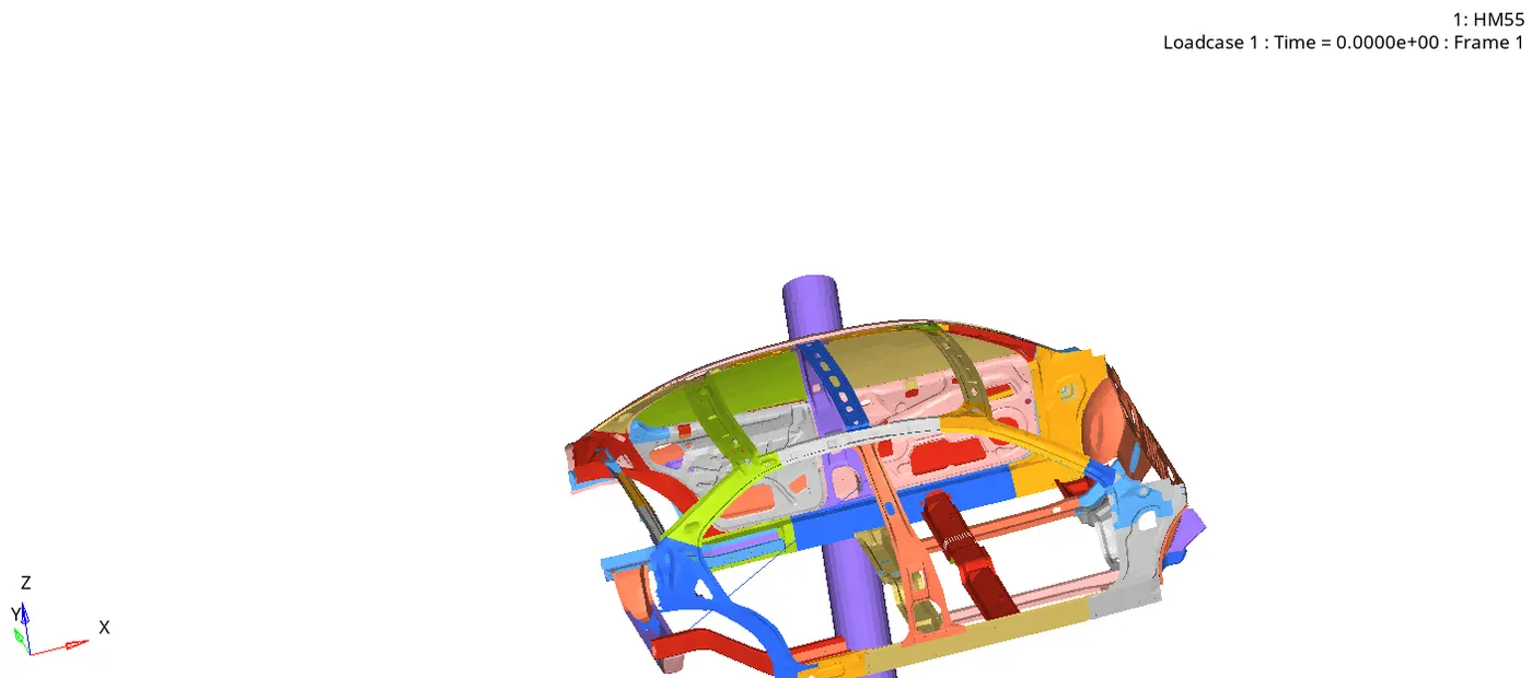
In this project, the simulation is set up for side pole crash by creating a Infinite cylindrical rigid wall for the model to impact mass balancing is done to achieve a target load of 700kgs and GC at a specified coordinate. Finally, the simulation is run and post-processing the results and capturing the sectional forces at different places in the vehicle to understand force flow, B-pillar & fuel tank intrusions and the peak velocity at the door are studied by following questions and output requests.
Questions:
Neon side crash-BIW
- Check unit system and either follow (Mg mm s) or (Kg mm ms)
- Create appropriate interface, friction 0.2 and recommended parameters
- Make sure of no penetrations and intersection.
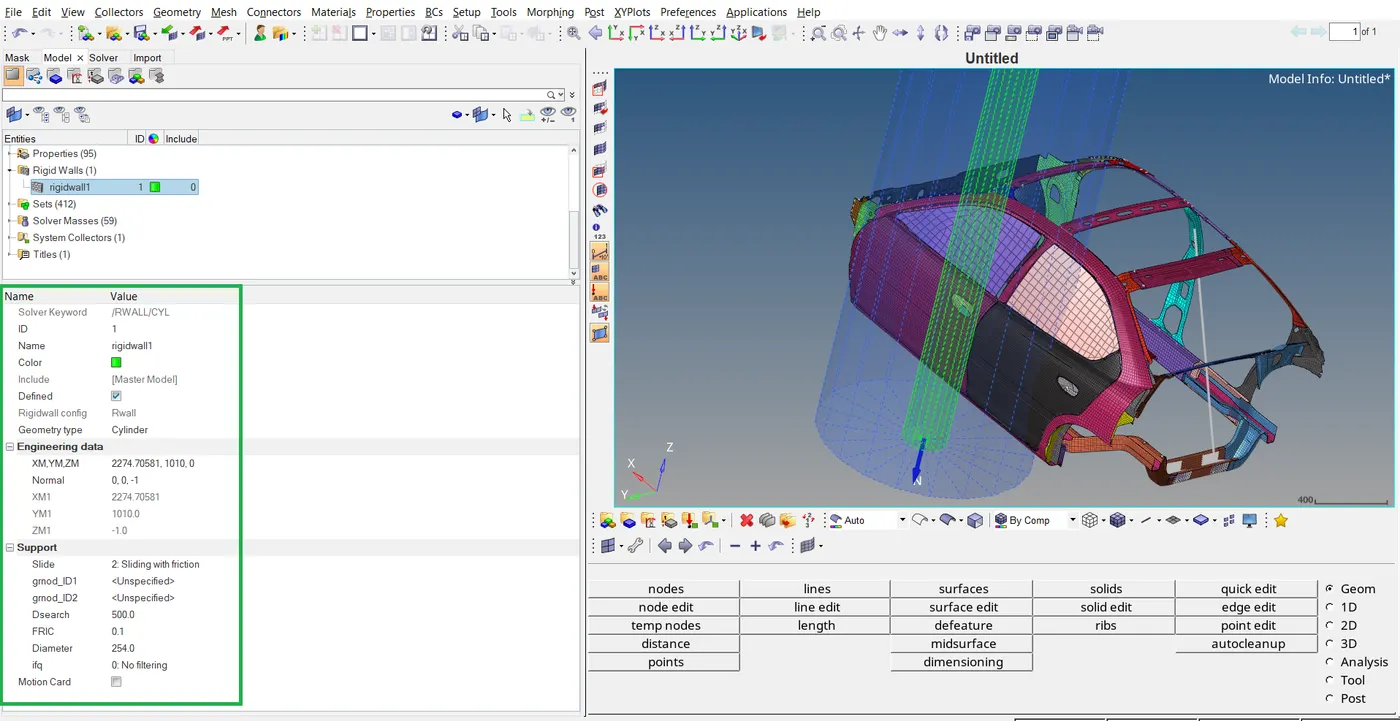
- Create rigid wall with friction 0.1 as per reference model.
- Compare the model weight with the reference model and use masses to reach target weight 700kg while getting the CG about the required range.
- Initial velocity 35mph.
- Use model checker to ensure good quality.
- Time step 0.5 to 0.1 microseconds.
- Run 80ms.
Output requests:
- Sectional force in the cross member.
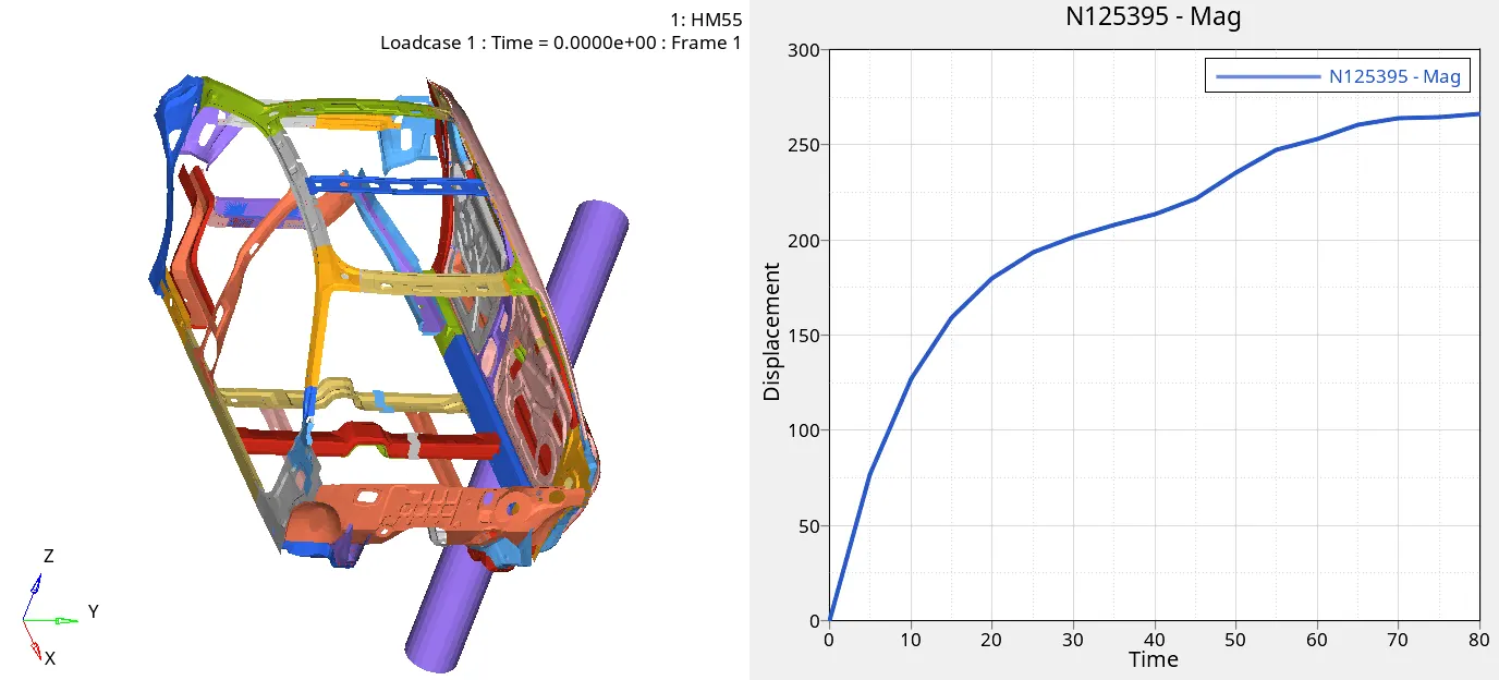
- Intrusions at B pillar, hinge pillar and fuel tank region. Provide recommendation on what can help to reduce Fuel tank intrusion.
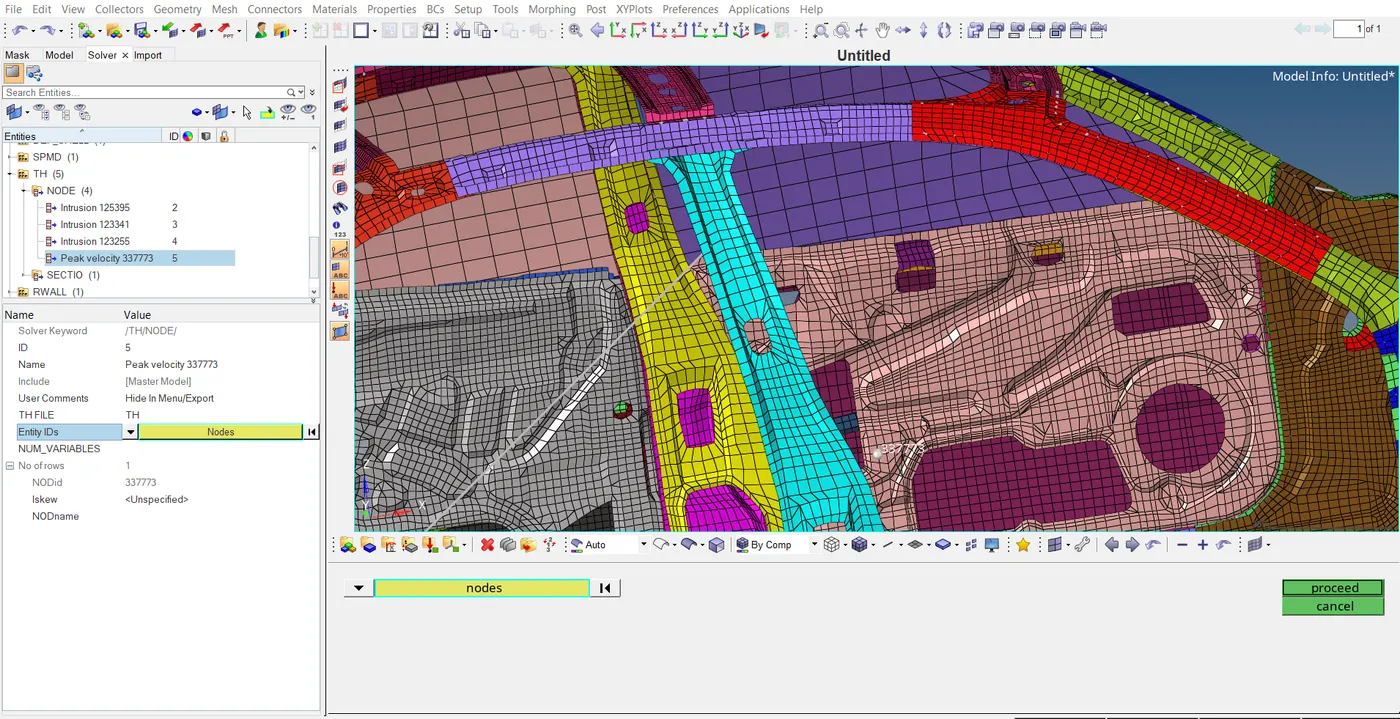
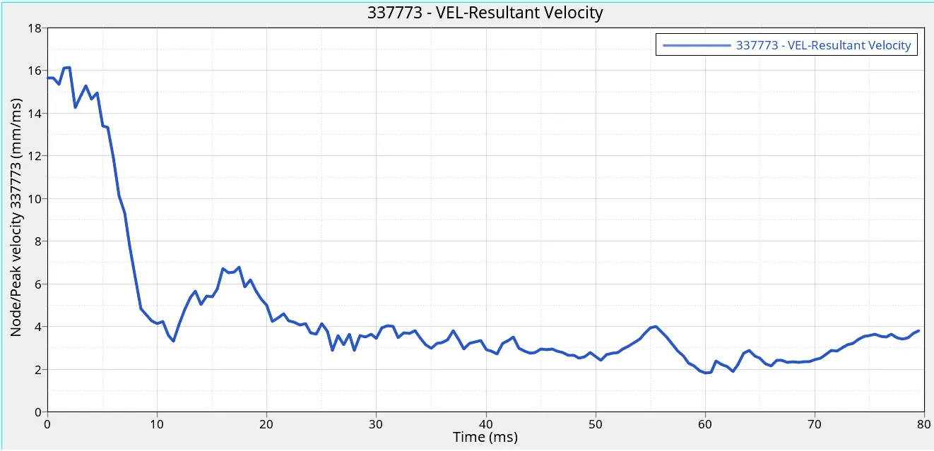
- Peak velocity of inner node of door.
Case set up and Execution with images:
Questions:
Neon side crash-BIW
1.Check unit system and either follow (Mg mm s) or (Kg mm ms)
Sol : To check the unit system open the given starter rad file neon_side_reduced_0000.Rad with a text editor and check the unit system which is followed.
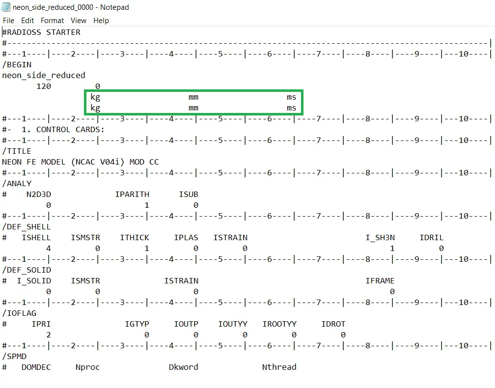
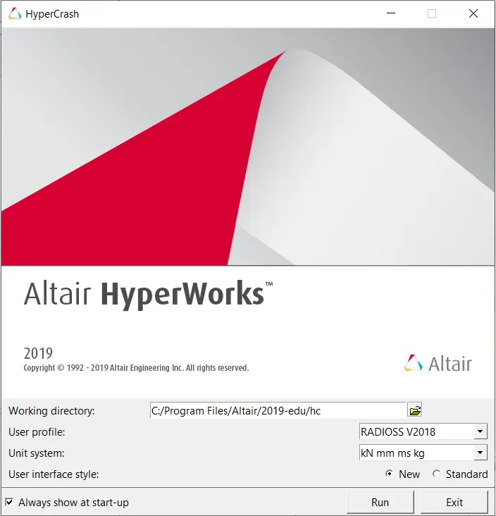
The unit system KN mm ms Kg is followed in this project because it is mostly used in industry and much more relevant to every day measurements.
2.Create appropriate interface, friction 0.2 and recommended parameters
Sol: Deleting the interface which is given in the model because of some errors in it. Importing the new Contact interface into entity browser by right click and by create new>go to contact interface>choose best contact interface which is recommended for crash applications.
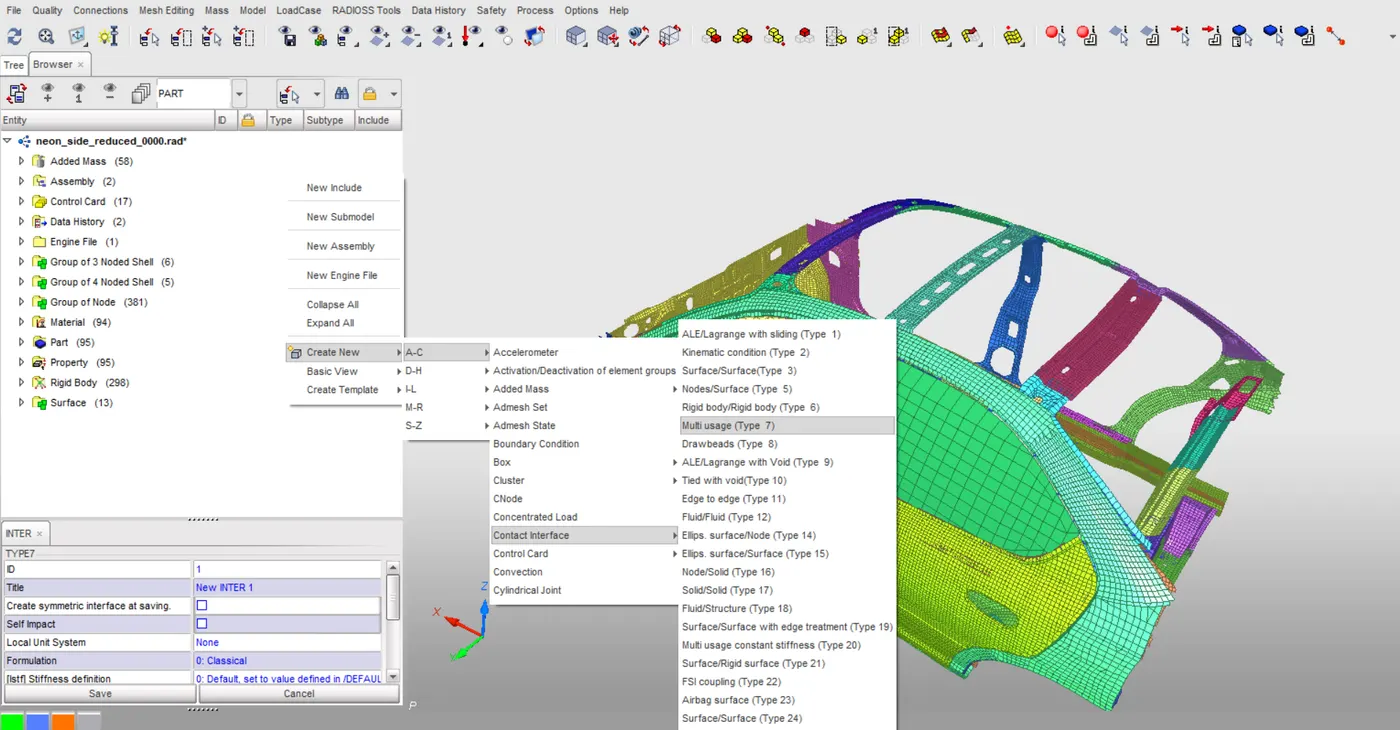
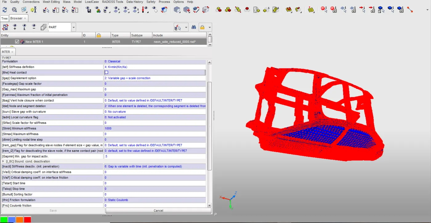
Creating contact interface 7 for all slave nodes and all master surface elements in the given model. Assign the parameters which are required for crash applications.
3.Make sure of no penetrations and intersection.
Sol: To check the penetrations and interactions in the hyper crash click on the Quality option from menu bar and open the check all solver contact interfaces.
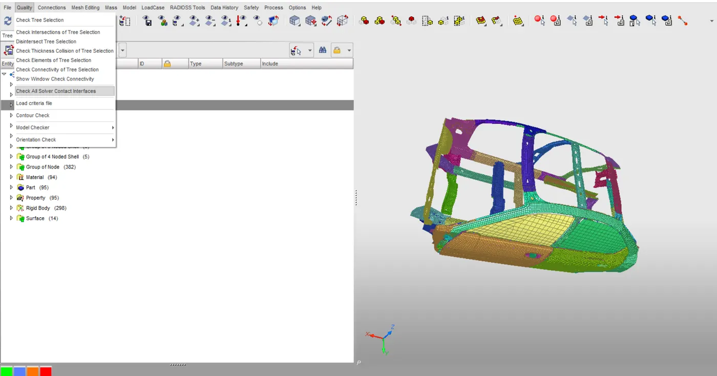
Checking the penetrations and intersections in Quality entity
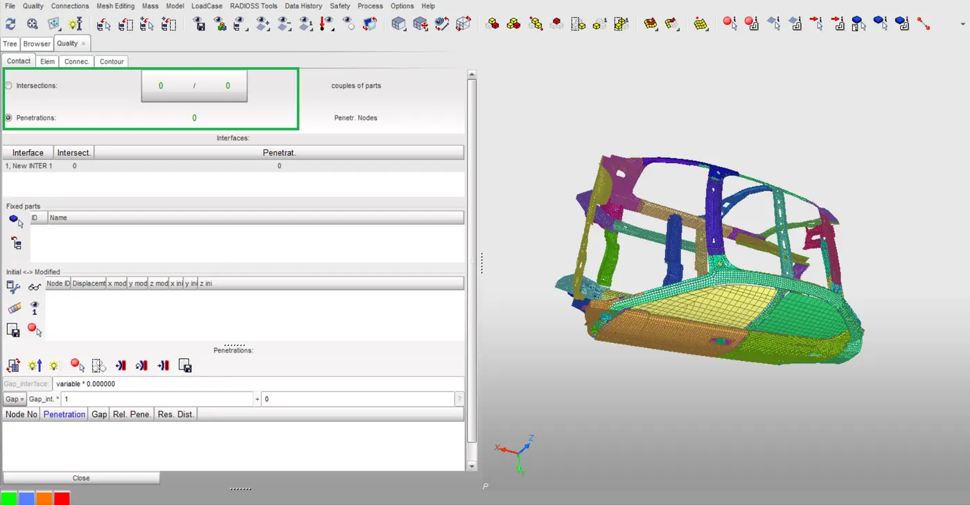
Hence, there is no penetrations and intersections available in the model.
4.Create rigid wall with friction 0.1 as per the referance model.
Sol: Creation of rigid wall entity in hypermesh followed by right chick in solver browser Create>RWALL>CYL
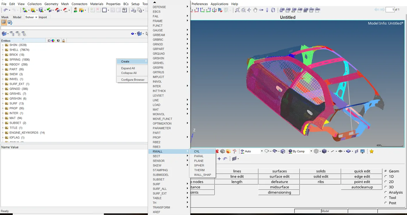
Then creating the base node M for x, y and z coordinates and normal vector from the base node from z axis. Giving the support parameters i.e., slide with friction 0.1, diameter of cylinder 254mm as per FMVSS standards and Dsearch 500 for rigidwall.
5.Compare the model weight with the reference model and use masses to reach target weight 700kg while getting the CG about the required range.
Sol: Checking the initial mass and CG point
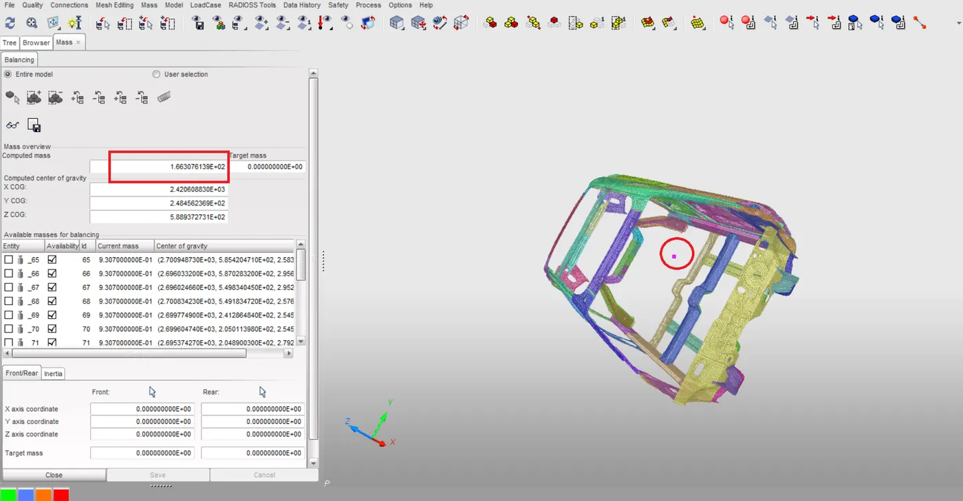
The initial mass is 166.308kgs and cg point is located at above the floor area.
Additional mass is added to the floor area of the car by using the option Mass is distributed each node group.
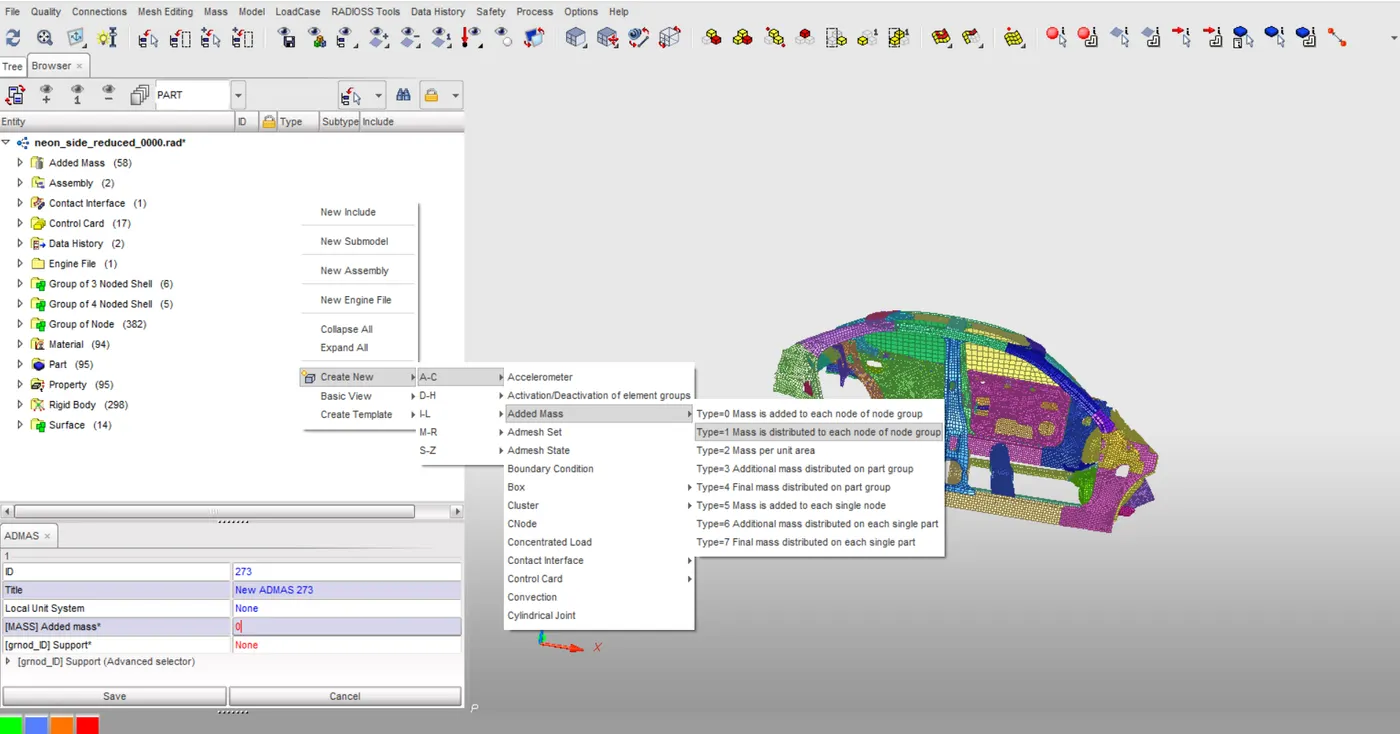
Adding the additional mass 533.69kgs added to cross members at floor area by selecting required nodes to increase mass to reach target mass 700kgs.
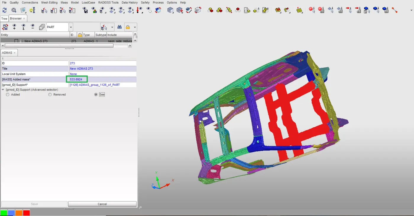
Checking the mass and cg point location after creating the additional mass
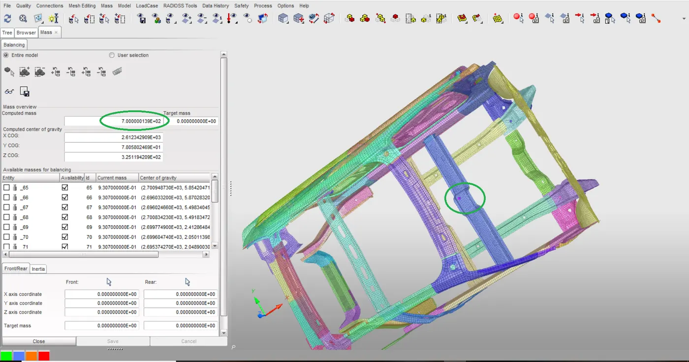
So, the CG point is moved to required location of floor area and mass is reached to 700kgs as shown in above picture.
7.Initial velocity 35mph.
Sol: Converting the 35mph to mm/ms. 35mph is equal to 15.6464mm/ms.
Selecting the node group on which the initial velocity are applied by Grnode_id.
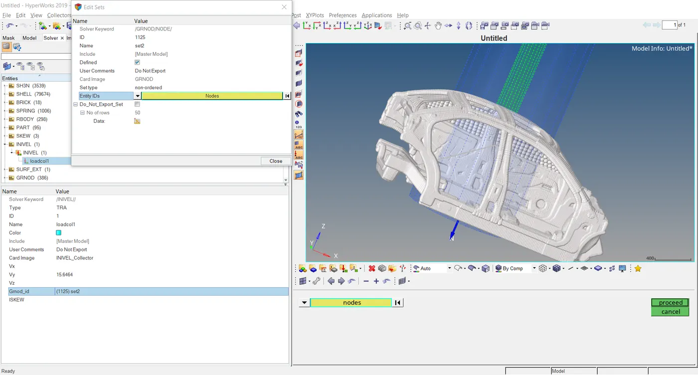
8.Use model checker to ensure good quality.
Sol: Open the model checker by going the Quality option on menu bar and hit run.
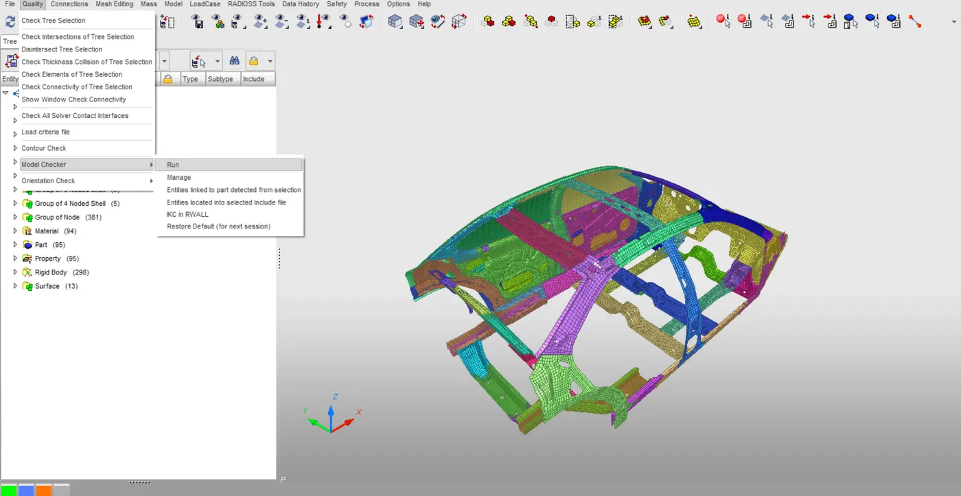
Checking the errors on the component
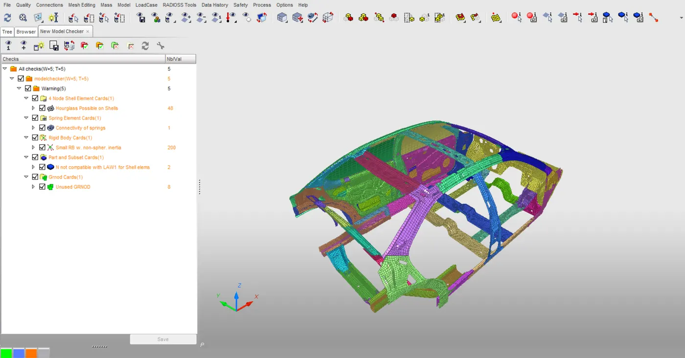
Hence the model is error free.
9.Time step 0.5 to 0.1 microseconds.
Sol: Checking the ENG_TFILE frequency for 0.5ms.
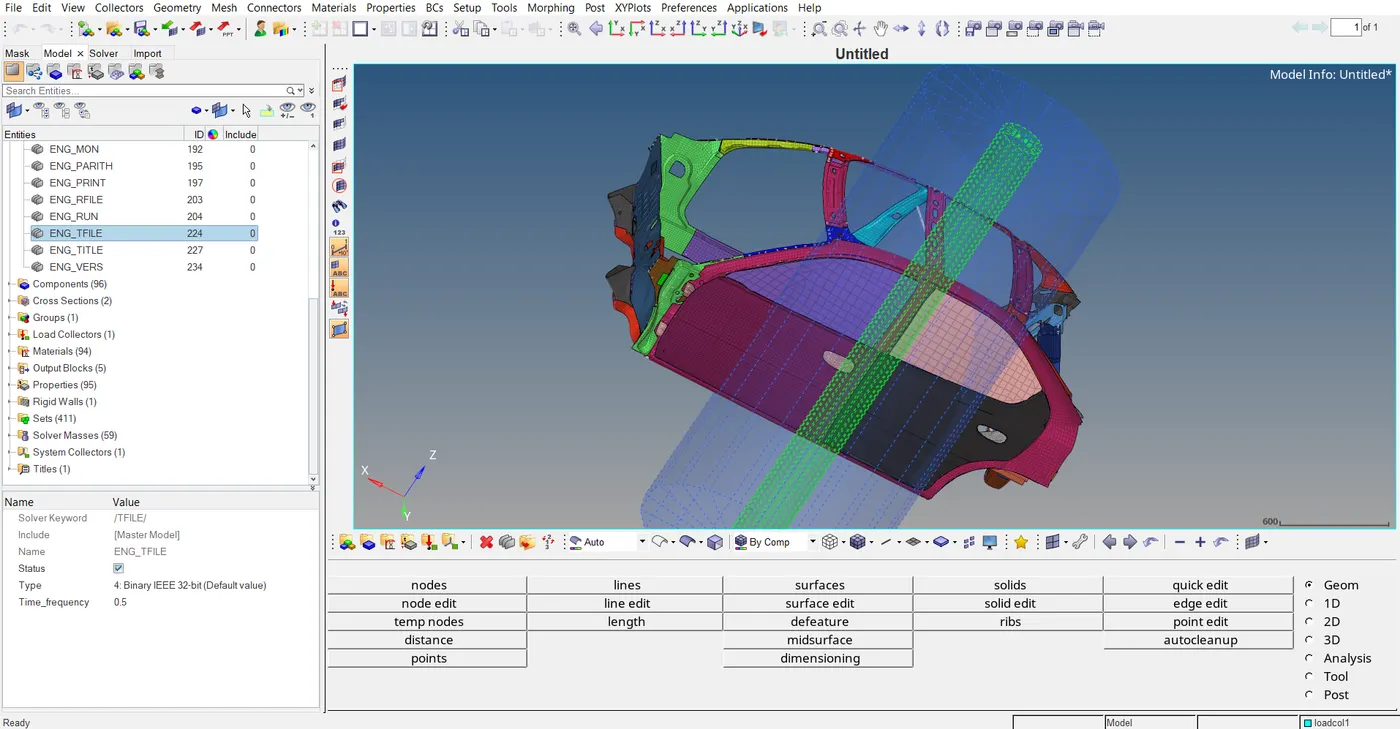
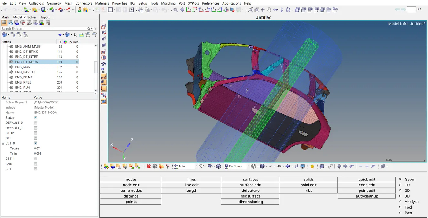
Checking the Element time step control card by DT/INTER/CST. By this the added mass on the contact when time step drops.
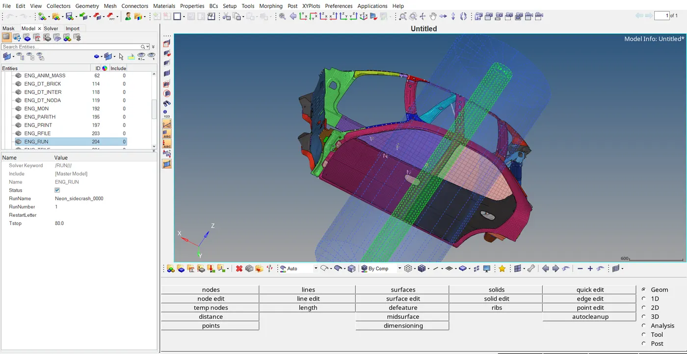
10.Run 80ms.
Sol: Checking the run time Tstop for 80ms in model browser cards entitie.
Output Requests:
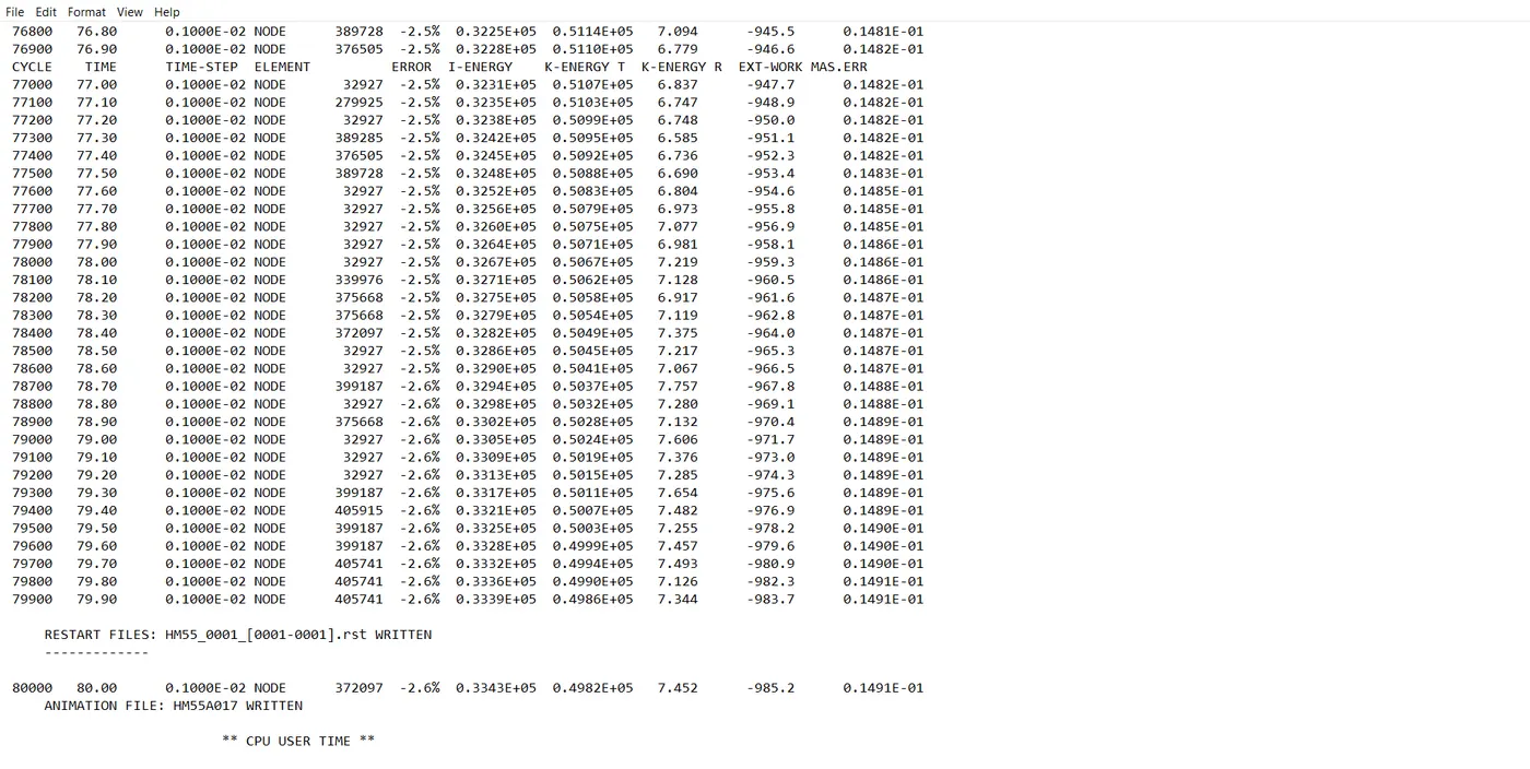
After running the simulation review the starter output file neon_front_0001.out file with a text editor and check the total number of cycles, energy error and mass error at the end of computation.
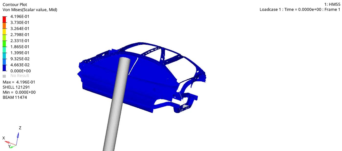
Contour plot of Von Mises
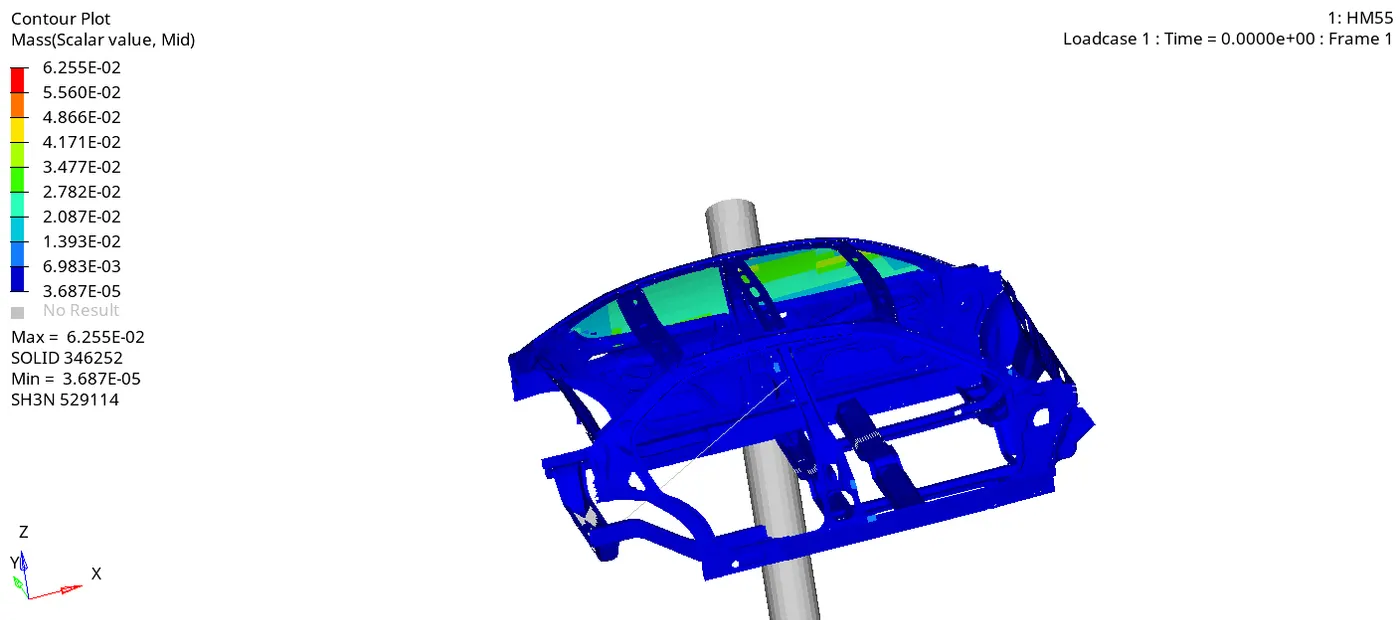
Contour plot of Mass
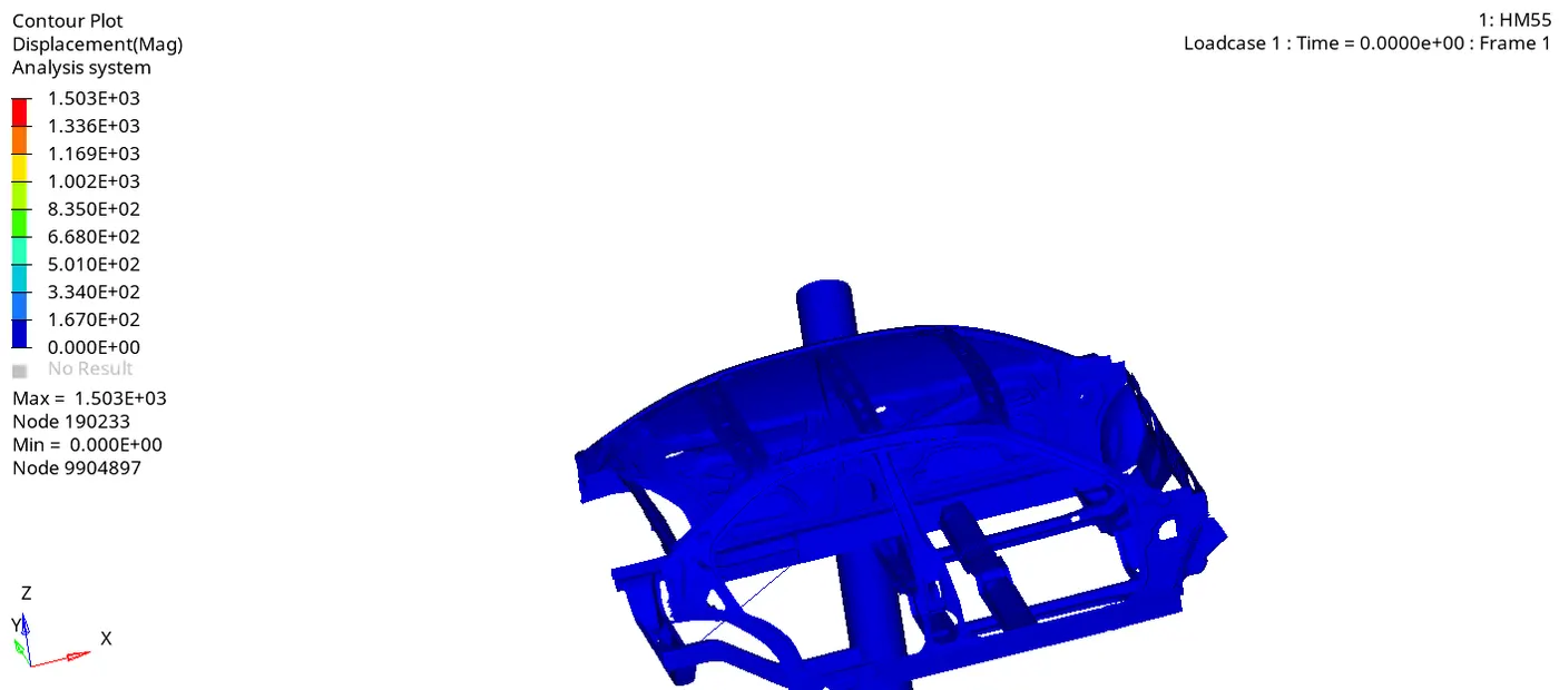
Contour plot of Displacement
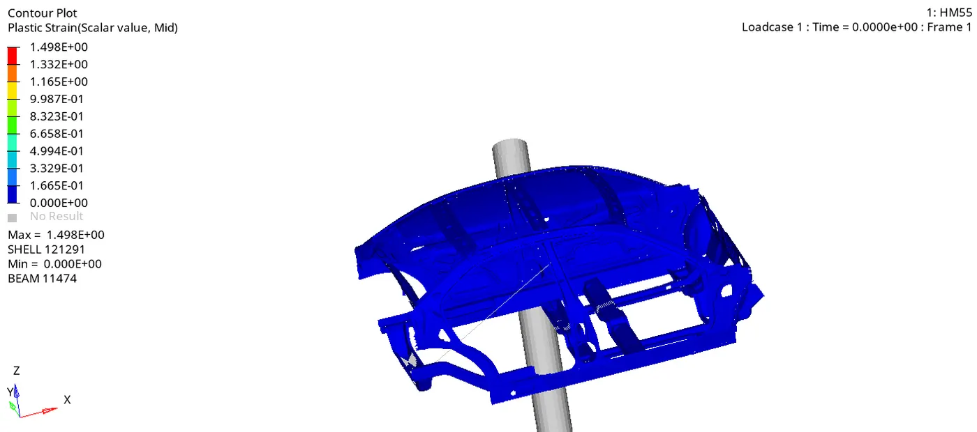
Contour plot of Plastic Strain
Contour plot of Specific Energy
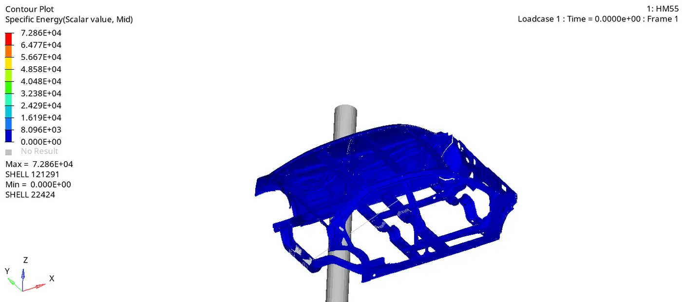
The energy error -2.6% and mass addition 0.1491E-01 are acceptable results for plotting the graphs. The simulation time is 6147.50sec and total number of cycles to complete the simulation is 80001.
1.Sectional force in the cross member.
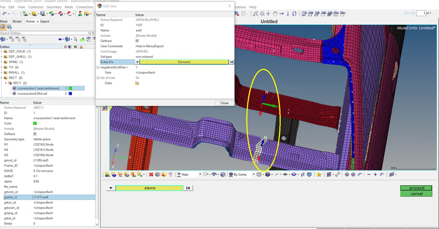
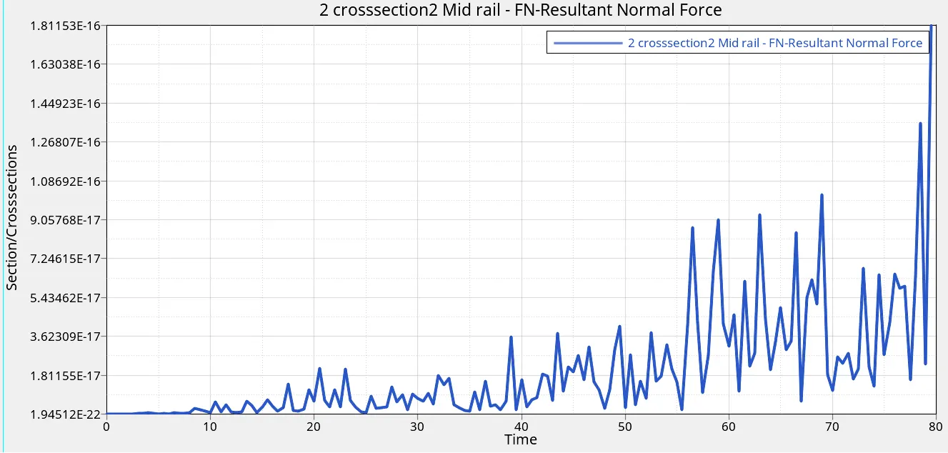
Sol: Creating new two cross sections at seat reinforcement and mid rail cross members. Then define the N1, N2, N3, nodes at particular location by grnod_ID, select elements in between the selected nodes grshel_id, ISAVE, delta T, alpha & Iframe.
Seat reinforcement and mid rail cross members:
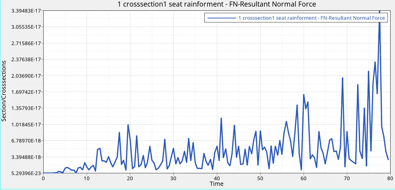
FN Resultant force at seat reinforcement cross member is shown in graph
FN Resultant force at mid rail cross member is shown in graph
2.Intrusions at B pillar, hinge pillar and fuel tank region. Provide recommendation on what can help to reduce Fuel tank intrusion.
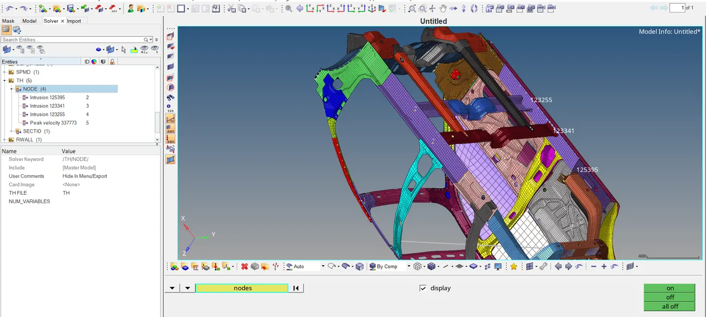
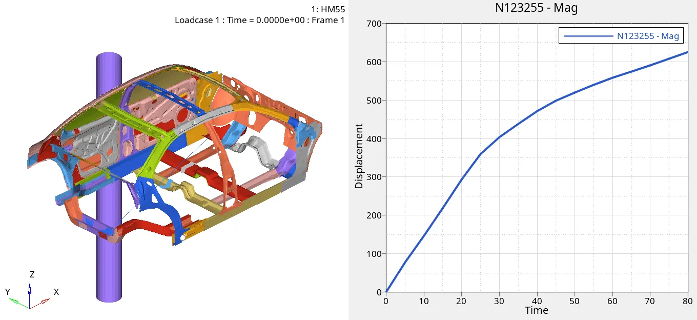
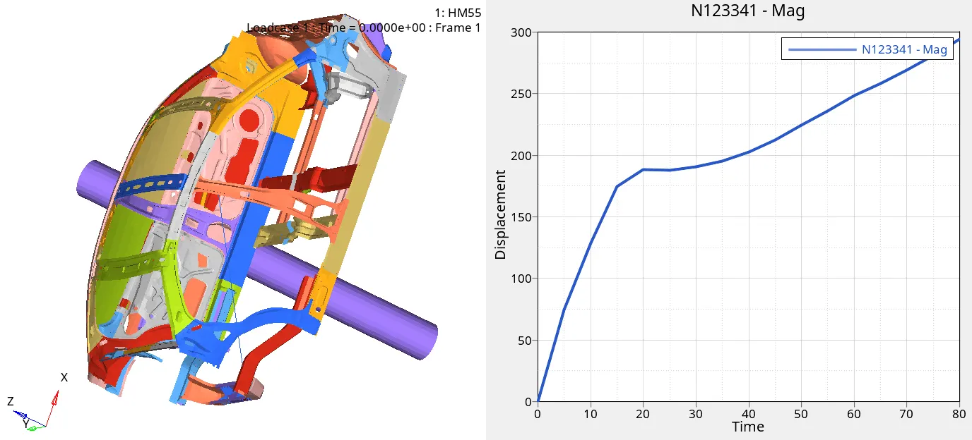
Sol: Creating the intrusions at B pillar, hinge pillar and fuel tank region by picking a node on at particular region as shown in the numbers and creating the skew to the opposite direction.
Resultant displacement for intrusion 123255 is 625.118408mm.
Resultant displacement for intrusion 123341 is 294.162384mm.
Resultant displacement for intrusion 125395 is 266.027802mm.
3.Peak velocity at inner node of door.
Sol: Creating node for calculating the peak velocity at the inner side of the door from time history entity in solver browser.
Maximum resultant velocity at inner node of door is 16.16mm/ms.
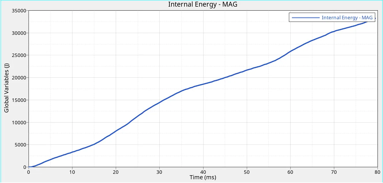
Maximum internal energy act at entire simulation is 33245.238281J
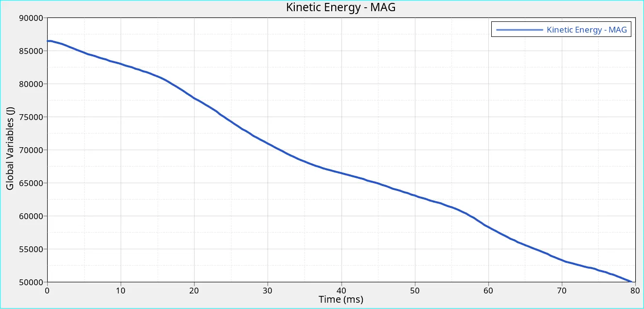
Maximum kinetic energy act at entire simulation is 86461.890625J
Result:
The simulation is set up for side pole crash by creating a infinite cylindrical rigid wall for the model to impact mass balancing is done to achieve a target load of 700kgs by adding the 533.69kgs to crossmembers in floor area and GC at a specified coordinate is done successfully. Various output results like peak velocity at the door (16.16mm/ms), Normal resultant force for cross members , Resultant displacement from B-pillar, hinge pillar, and fuel tank intrusions are calculated and plotted in the graphs.
Conclusion:
By this project I am able to learn about how to create the interface for all nodes and elements, how to create rigid wall with friction 0.1, how to adding the mass to reach target 700kgs and to locate CG at particular location, creation of infinite cylindrical rigid wall, creation of initial velocity, how to check and eliminate the penetrations, interactions, rigid bodies and errors in the model & creating the different output blocks for calculating the displacements at intrusions, peak velocity at inner door and normal resultant forces from different cross sections.
G-drive link:
https://drive.google.com/open?id=1ko4X6lohgxAjJjRnxx2cKcgjJUOyA1Nc