Side Crash Test with Guidelines of FMVSS 214 Standard by using Radios
Frontal crash-BIW
- Check unit system and either follow [Mg mm s] or [Kg mm ms].
- Create appropriate interface ,friction 0.2 and recommended parameters.
- Make sure of no penetration and intersections.
- Create rigid wall with friction 0.1 as per referance model.
- Compare the model weight with the referance model and use added masses to reach target weight 700kg while getting CG about the required range.
- Initial velocity as shown in picture.
- Use model checker to ensure good quality.
- Timestep :0.5 to 0.1 microseconds.
- Run 80ms.
Output requests:
- Sectional force in the cross member.
- Intrusion at B pillar,hinge pillar and fuel tank region.Provide recommendation on what can help to reduce Fuel tank intrusion.
- Peak velocity of inner node of the door.
SOLUTION:
- Import File neon_front_0000.RAD
- Open RAD File to check the unit system
- Unit system being followed is Kg | mm | ms
- Go to Model > Groups > Clear existing interfaces present.
- Create new contact > Include neon_front > Card Image as Type 7
- Use Recommended Crash application data,

- Select Master Elements and Slave nodes to the type 7 interface.
- Friction value as 0.2
- Go to Tools > Penetration Checker > Check
- Check for the errors present
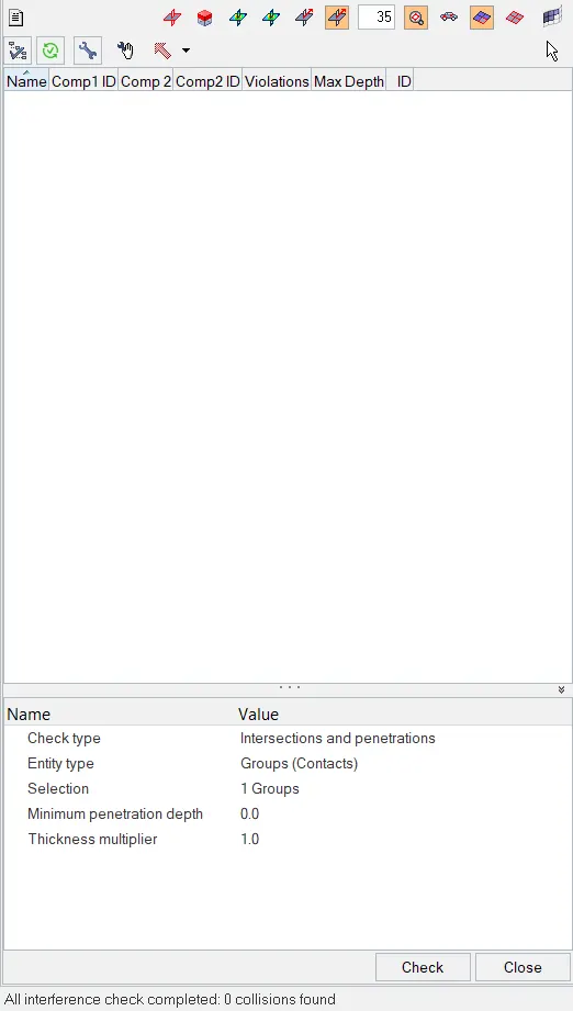
- There are no errors present in the model
- To Correct rigid bodies if any issues.
- Tools > Find connectivity > Check
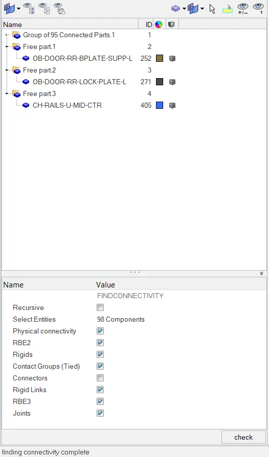
- There are 3 Free components present in the system.
- Since those are free parts which is not connected but still it is near the connected parts, which is left unconnected.Use 1D > Rigid body , to connect them to nearest functional part.
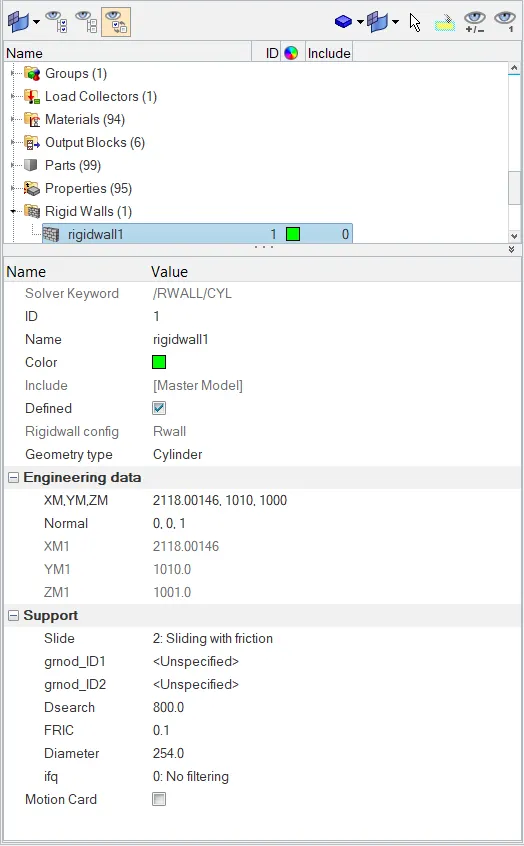
- To create rigid Pole with friction of 0.1, go to Create > Rigid Walls.
- Using node, select the point to create reference point for the infinite plane.
- Use normal option to create the direction of the wall to act.
- Select Slide > Sliding with friction.
- Dsearch is used to induce the search distanct of the master to act upon.
- Input the friction value as 0.1
- To add mass to the model, target weight 700kg while getting CG about the required range
- Export file into radioss
- Go to Applications > Hypercrash
- set units as set in Hyper mesh as mm | Kg | ms > Run
- Click on added mass to view masses added on model
- To view COG , Go to Mass > Mass Balancing.
- To add mass Go to added mass section, Go to create new object
- Select Type 1 - Mass distribuited to each node of node group.
- In added mass input mass to be added, and select the nodes using selection.
- click save
- Go to Mass tab and click on view to preview COG
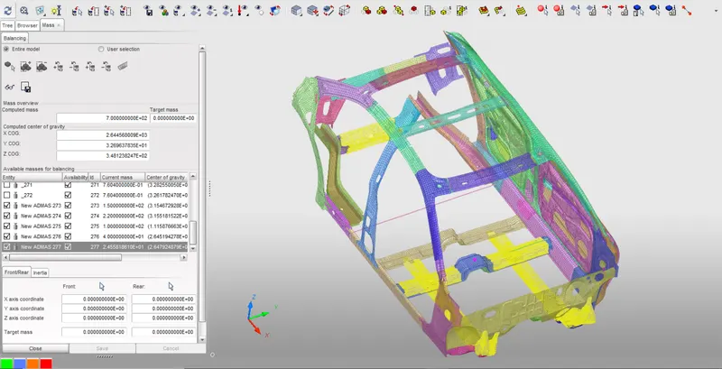
- Export the file as .RAD File to reopen in Hyper mesh
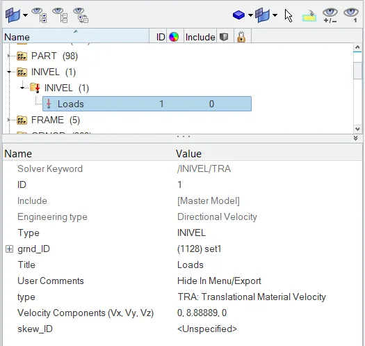
- To create the initial velocity of 32km/h i.e, 8.88mm/ms.
- Go to in Solver section > Boundary conditions > Inivel
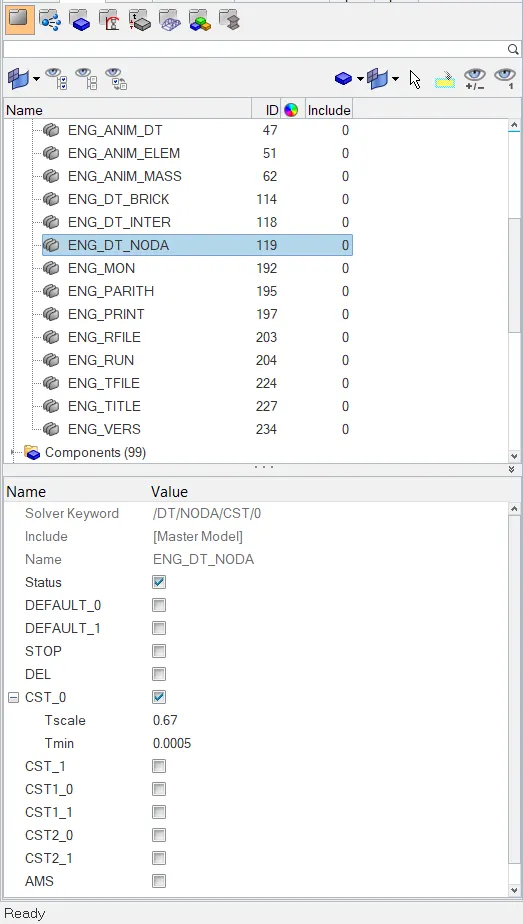
- To change Time-step between 0.5 to 0.1 microseconds.
- Go to Model > Cards > ENG_DT_NODA
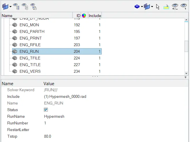
- To run Run 80 ms.
- To change Time-step between 0.5 to 0.1 microseconds.
- Go to Model > Cards > ENG_RUN
SPECIFYING BRITTLE FOR DOOR GLASS:
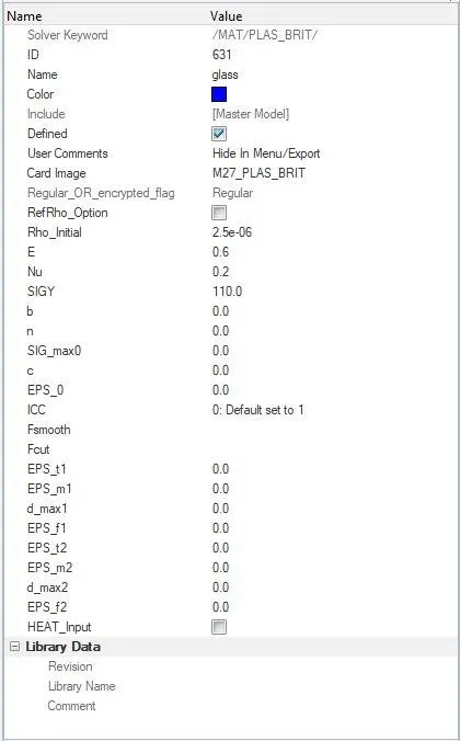
- Identify the material card by selecting the door glass
- Mat ID 295,297 are to be applied with the below parameters with M27_PLAS_BRIT
- Curve data defined for the function identifier in the faiure card.
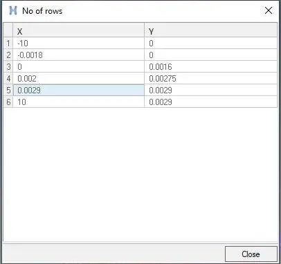
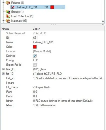
- Create Failure Card is used to model the brittleness for the glass.
- The curve created previous for the failure is defined in this johnsons failure card.
- The below parameters are given for the defining the Johnsons failure card in the door glass.
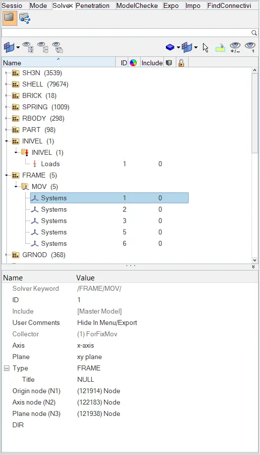
- To find Sectional force in the Cross member, Go to Solver tab > Create > Frame > Movinf Frame > Choose nodal point such that Z axis is normal
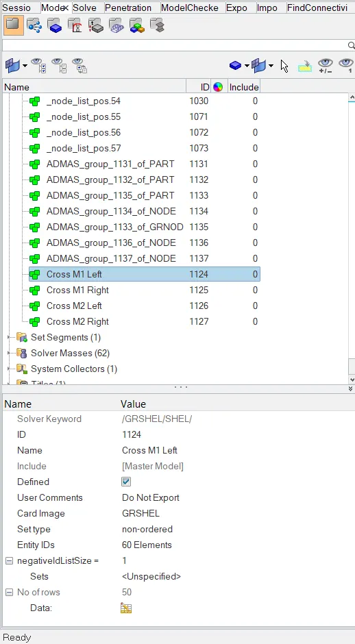
- Go to model tab > Set > Section 1 > Select the elements to be sectioned.
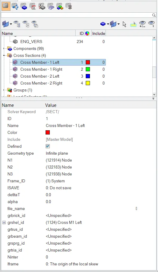
- Go to Create > Section > In cross selection, select the nodal points placed in frame > select frame ID
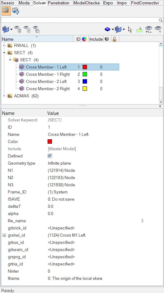
- Go to Time History > Create >Section > Select entity as Rail section
- Follow this procedure for all the cross section to be made in, shotgun section, Rails, A pillar.
- Intrusion at B pillar,hinge pillar and fuel tank region.Provide recommendation on what can help to reduce Fuel tank intrusion.
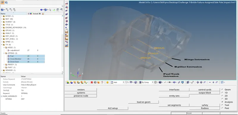
- We can create using nodes and also springs, here we use Spring to check the intrusion at B pillar, Fuel tank and hinge region
- Got to 1D Elements > Springs

- Select One node at the area required and another on opposite side.
- To find Peak velocity of inner node of the door.
- Create node at a point (ID : 337773), Solver > TH > Nodes > Select the ID 337773.
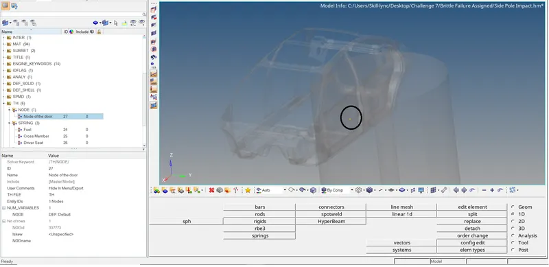
- Click Analysis > Radioss > Give Options as -nt 4 > Radioss.
Output File
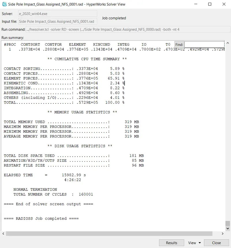
ERRORS:
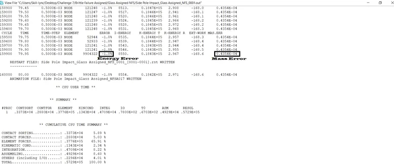
Energy Error : -1.8% (Acceptable)
Mass Error :0.4354E-04 (Acceptable)
HYPERVIEW SIMULATED OUTPUT:
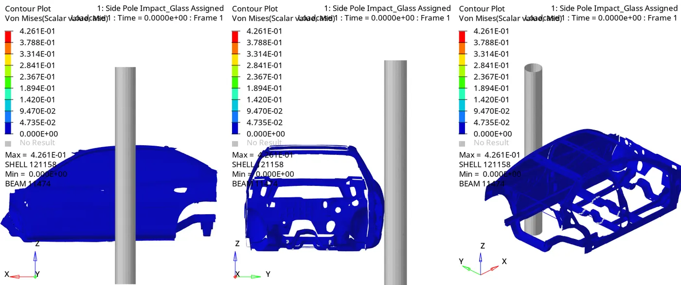
SECTION SPLIT IN CROSS MEMBER:
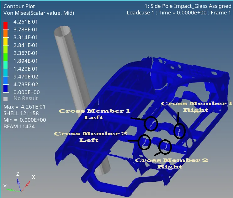
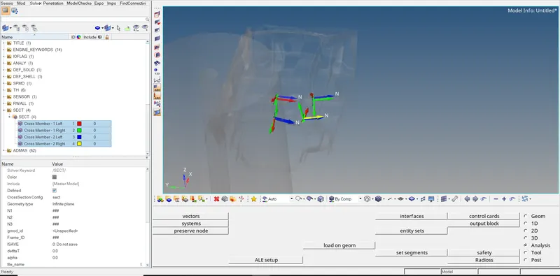
Cross members is sectioned as 4 parts as shown in the image.
CROSS MEMBER 1:FORCES ACTING ON SECTION
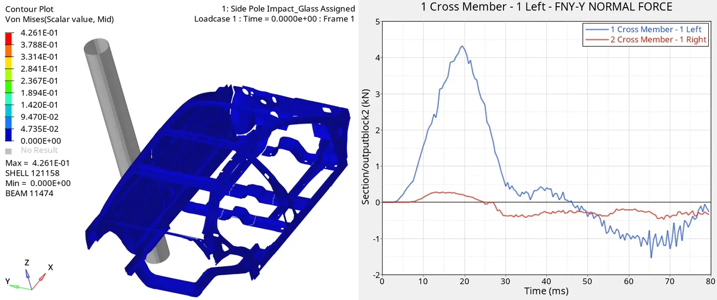
- Peak force of 4.4KN is acting on left portion of cross member which valleys between 5-30ms of the crash
- Peak force of about 0.5KN is found on the right portion of the cross section.
CROSS MEMBER 2:FORCES ACTING ON SECTION
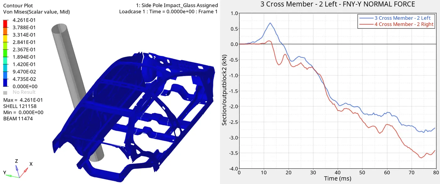
- Peak force of 2.8KN is acting on left portion of cross member which reaches maximum at the end of 80ms
- Peak force of about 3.7KN is found on the right portion of the cross section as the part involves with the rigid pole.
INTRUSION AT B PILLAR, HINGE PILLAR AND FUEL TANK REGION. PROVIDE RECOMMENDATION ON WHAT CAN HELP TO REDUCE FUEL TANK INTRUSION:
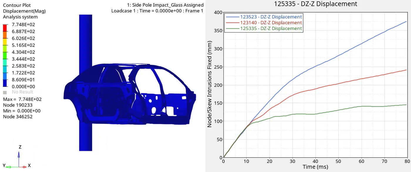
- Node ID: 123523, is an part lower hinge region, which is displaced maximum of about 374.707mm, along z axis of the skew assigned to it.
- Node ID: 123140, is an lower region below B Pillar, which is displaced of about 241.99mm, along z axis of the skew assigned to it.
- Node ID: 125335, is an fuel tank region of about 145.168mm, along z axis of the skew assigned to it.
RECOMMENDATION FOR REDUCTION OF INTRUSION IN FUEL TANK REGION:
- Adding stiffness to the frame:
Flanging : Bending the boundary of the sheet slightly in an L shape where it can be done.
Hemming : Similar to flanging , shaping into U, in which it is done L in flanging.
Emboss : this feature is added by offsetting the plane of the sheet in a local area . There by greatly improving stiffness.
Dimples : In the case of cantilever brackets . Adding dimples at the bends greatly improves the stiffness and restricts deflections. Even otherwise they are helpful in improving stiffness for most applications.
Ribs : these are combination of either dimples or embosses in a pattern . Doing the same work but for a larger area.
- Providing stiffeners in the region, adding strength:
when all the above feature additions fail to provide you with required rigidity its better to add extra brackets, plates for stiffness. The manner in which you add them would be governed by the direction in which you want to increase stiffness.
Depending on thickness the applicability of these methods may vary.
Lower thickness = more possibilities.
Process parameters are important to avoid tear and too much thinning. Which may compromise durability.
- Change of materials.
PEAK VELOCITY OF INNER NODE IN THE FRONTAL DOOR:
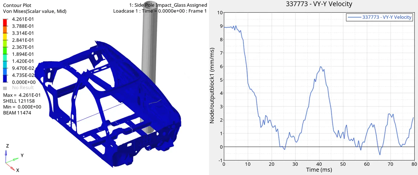
- The peak velocity of 9mm/ms at the initial crash time at the node 337773, which is traced to yellow line in the frontal door.
ENERGY PLOT:
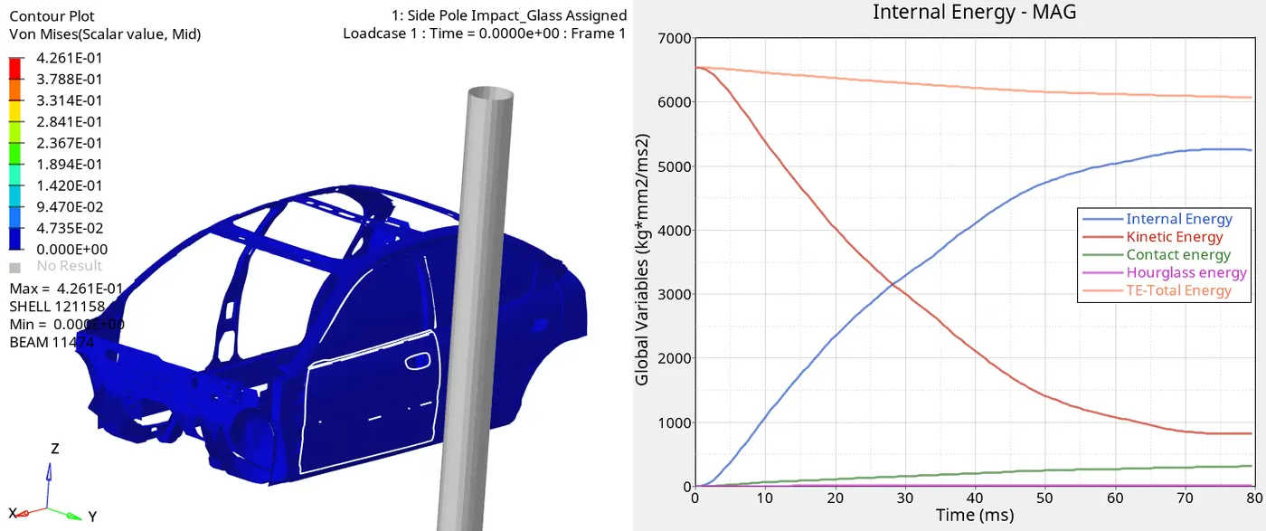
- The Total Energy due to the crash event is 6500 Joules.
- The kinetic enegy is maximum of 6500 joules at the inital state as initial velocity of 8.88889mm/ms, it hits rigid pole, thereby decreasing at 80ms.
- The internal energy startes at the time of crash due to the heat and work done which is the crumbling of the component , at 80ms it is about 5250 Joules.
- Contact energy is the energy released during the crashing, which is inversely proportional to the total energy, which is found decreasing with increase of contact energy.
- Hour glass energy is observed of 13 Joules, which is very low and satisfying.