Assignment 6-Frontal Crash Simulation Challenge
PROCEDURE:
CREATE RIGID WALL:
In Hypercrash: Load case - rigidwall - create - plane
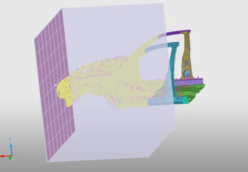
Specify the tail and vector normal of the rigidwall by selecting nodes at the front bumper
Set ~200mm distance apart from node on car model
Set frictional coefficient as 0.1
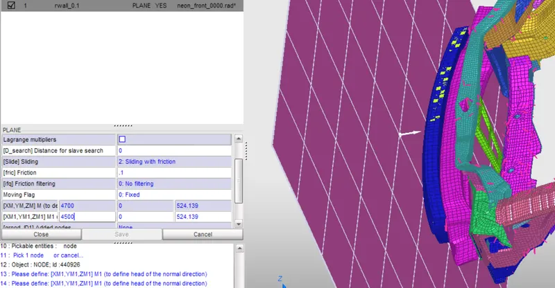
With a search distance of about ~2000mm from the rwall
INITIALIZE INTIAL VELOCITY
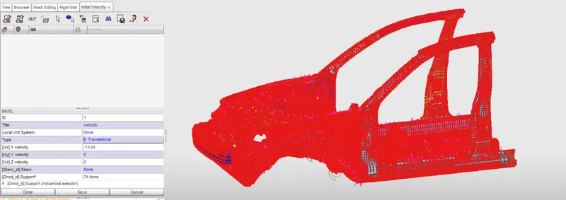
Create initial velocity card under loadcase. Set up a translational velocity along the x-direction of about 35mph which is equivalent to 15.64 m/s or mm/ms.
CREATE INTERFACE CONTACTS:
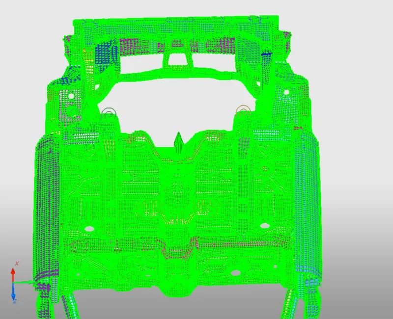
Delete existing contact interfaces which only recognize individual parts as slave and masters as such if an interface comes in contact with slaves of another penetration would happen since no interface is defnied.
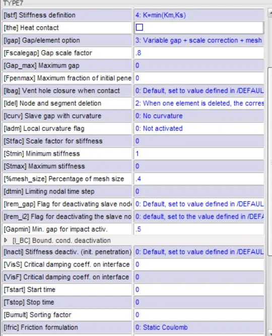
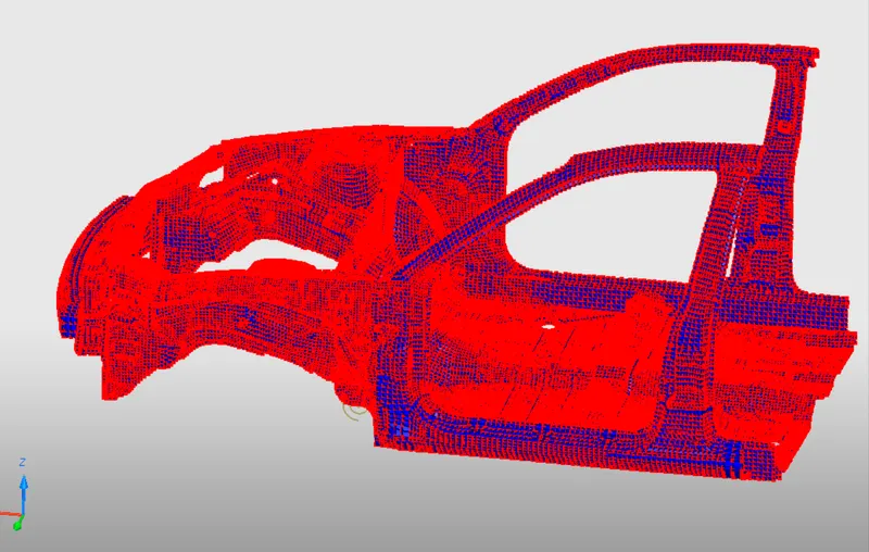
Hence specify a new TYPE 7 node to surface self contact of the whole component
Select slave nodes and master segm as the nodes and segment of the entire part with the following params:
Istf:4 - Computes based on the stiffness of the softest of the slave/master
Igap:3 - Variable gap+ scale + mesh size
with Fscale_gap=0.8 and %mesh size=0.4
Idel:2 - remove segm when a single elem fails
Stmin = 1000N/mm or 1kN/mm
Iform:2 - change penalty formulation from default of Viscous to based on stiffness
CHECK INITIAL PENETRATIONS
We can run contact interface penetrations checker under loadcase-contact interface
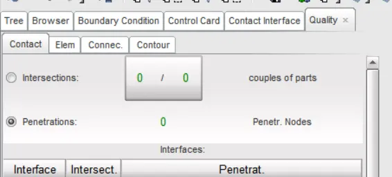
If any penetrations exist, they can be manually removed by modifying contact interface card params or with the provided features by the above checker.
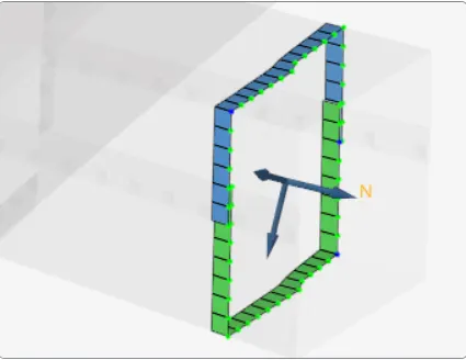
SECTIONAL FORCES
This helps us analyze different forces/energies experienced at different sections of the model. How the absorbed strain energies and internal energies are transmitted from the area of impact i.e front bumper towards the a,b pillars and rails.
To create a section in HC:
Datahistory-section-create
else can also be created in Hypermesh as: Create-sect-specify local c.s under frame_ID and shell elems under grshel_ID.
Set time history output frequency <0.5 (~0.1) and Exponential moving average filtering constant to the recommended value of 0.62832
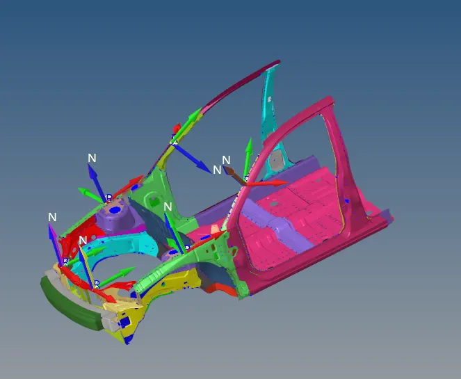
NOTE: The sections can be manually specified using N1,n2,n3 and selecting required elems.alternatively using frame id
CREATE ACCELEROMETER
In HM: create-accel-select nodes.
The position of nodes are selected nearby rocker. A single node on either side for two accelerometers. with the freq at which the data is written out specified in each individual card as 0.1
SPECIFY OUTPUT BLOCKS
Request output files for rwall, secforce, contact force, accelerometers etc.
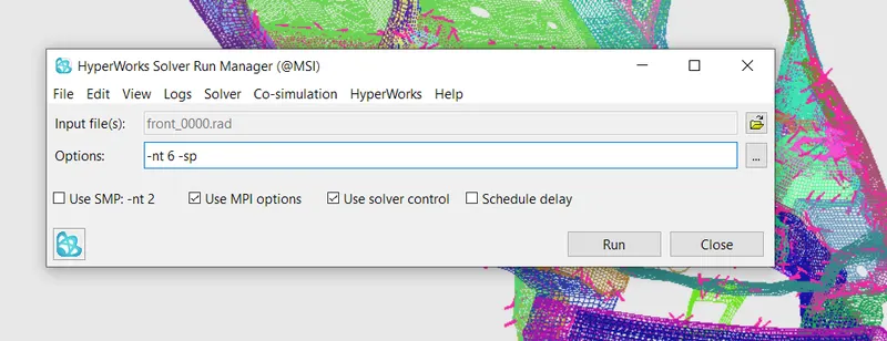
SUBMIT
Submit the job onto the radios solver with the number of threads and method of processing defined under options
POST PROCESSING
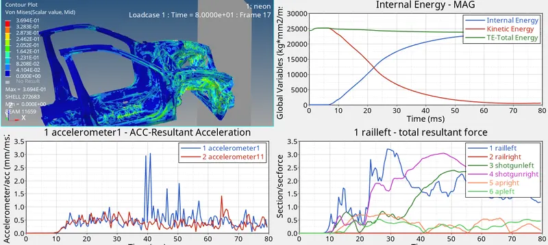
- The von-mises stress observed to be at max of 0.3KN/mm or 369N/mm or 369Pa which is above the elastic yield strength of the BIW al material which indicates plastic deformation occurs in the model.
- The strain energy absorbed by the frontal part (resilience) is well absorbed by the bumper thereby reducing the impact propagated towards the a-pillar which could be detrimental to a passengers safety. Due to plastic deformation it could also be noted that kinematic/isotropic hardening employed further negates the stress propogation
- The energies plot shows the conversion of kinetic energy into internal energy as the impact occurs and progresses throughout the model
- The accelerometer placed at either ends of the model (i.e at the rockers) indicate the vibration or rate of vel change occurred at that region. The spike at acc1 compared to acc2 is due to their distance from the area of impact (front-end).
- The sectional forces also indicate a clear picture based on our assumptions. The rails experience the impact at a shorter time frame followed by shotgun and a-pillar due to shock wave propagation through the biw. The magnitude of the force experienced at the rails and shotgun are significantly higher that those experience beside the passenger side i.e the a-pillars. Hence it is safe to conclude the impact experience by occupants is greatly minimized.
- The magnitude of forces at rails being relatively higher than the shotgun implies either small cross-section of the rails assuming the material is same. Else the rails being the area to incur most of the reaction force from the rwall. This could be further negated by modeling the rails with a stronger material like steel and then further back around pillar employing a material like aluminium which has relatively less weight and strength.