Assignment 6-Frontal Crash Simulation Challenge
Frontal Crash test
AIM:
Frontal car crash simulation of Dodge Neon BIW using RADIOSS solver and Preprocessing using HyperMesh / HyperCrash.
OBJECTIVE:
- Check the unit system and either follow [Mg mm s] or [Kg mm ms].
- Create an appropriate interface, friction 0.2, and recommended parameters.
- Make sure of no penetrations and intersections.
- Correct rigid bodies if any issues.
- Create a rigid wall with friction 0.1.
- Compare the model weight with the full-scale 300k nodes model and use added masses to reach the target weight of 700kg while getting CG about the required range.
- Initial velocity 35 mph.
- Use a model checker to ensure good quality.
- Time-step: 0.5 to 0.1 microseconds.
- Run 80 ms
Output requests:
- Sectional force in the rails at location of indicated node 174247.
- Axial force received on the rails from bumper.
- Shotgun cross sectional forces.
- A pillar cross section.
- Acceleration curve received on the accelerometer at base of B pillar (on B pillar rocker).
- Intrusions on the dash wall 66695,66244.
PROCEDURE:
We will be using Hypercrash and Hypermesh to set up the model. Some checks will be done in Hypercrash and some in Hypermesh. First, we will import the model into Hypercrash and check for Penetration and make sure the units are in Kg mm ms.
The unit check can be done without opening the model. We can just open the Neon_front_0000.rad in a notepad where we will be able to check the units.
Unit System:
For units, browse
Model > Cards > BEGIN_CARD
We can see that the Units are in Kg mm ms. Now we will open Hypercrash and perform a penetration check and also will be adding mass to the body.
Penetration and intersection:
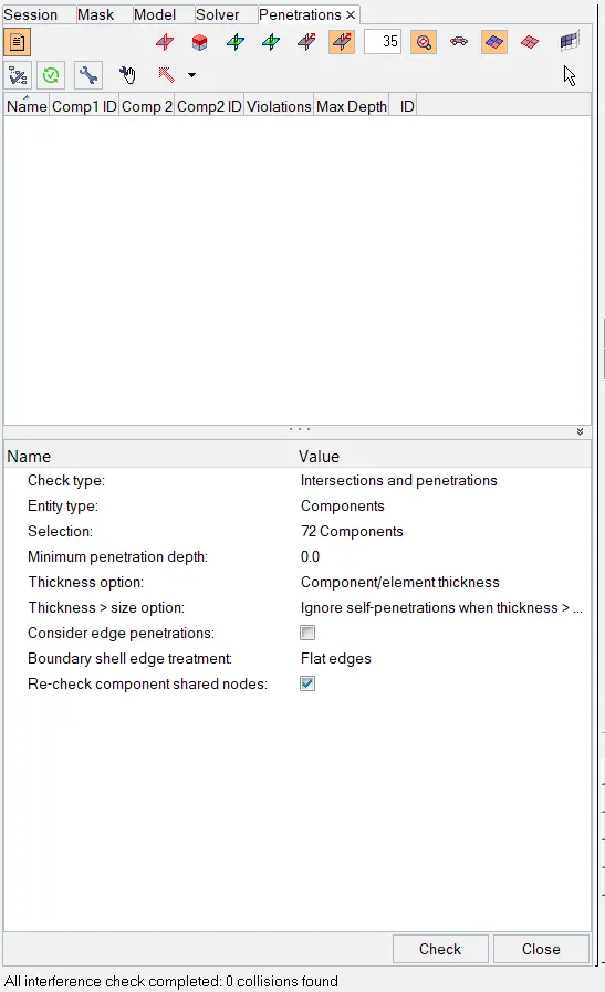
Zero penetration or intersections found.
Reach the target weight of 700 kg while getting CG about the required range:
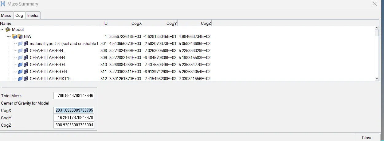
To compare the model weight with the full-scale 300k nodes model and use added masses to reach a target weight of 700kg while getting CG about the required range. The given model was less in mass with 188 kg. Check by using Tools > Mass Details > Mass, cog, and inertia, and check the mass.
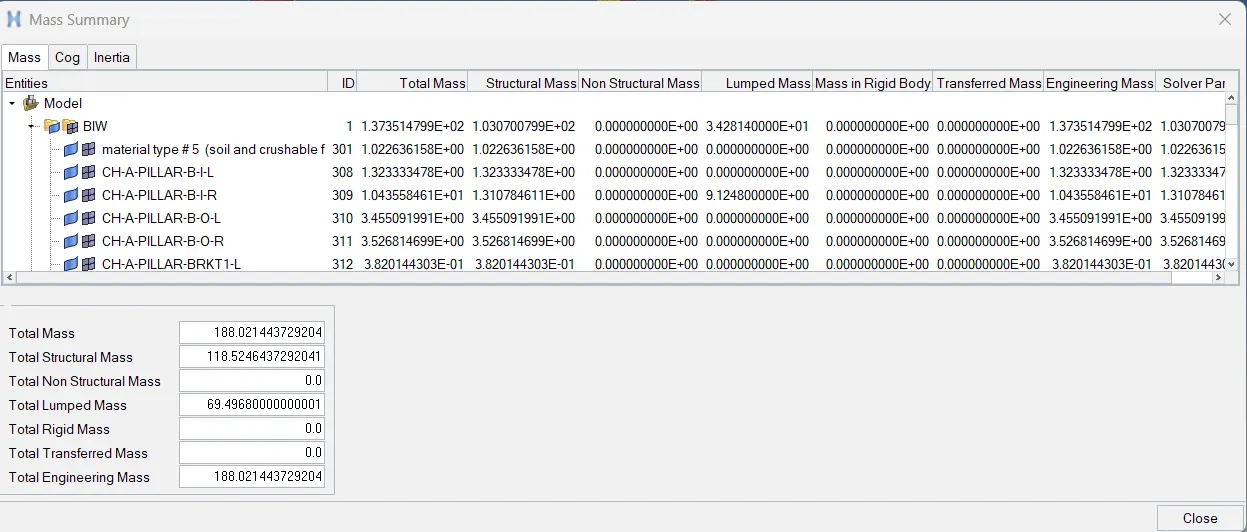
Existing weight of mesh geometry: 118 kg
Required weight : 700 kg
Additional mass to be added: 582 kg
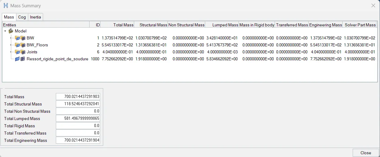
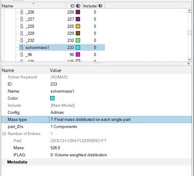
following is the achived COG location,
Applying initial velocity:
solver > create > boundary conditions > inivel
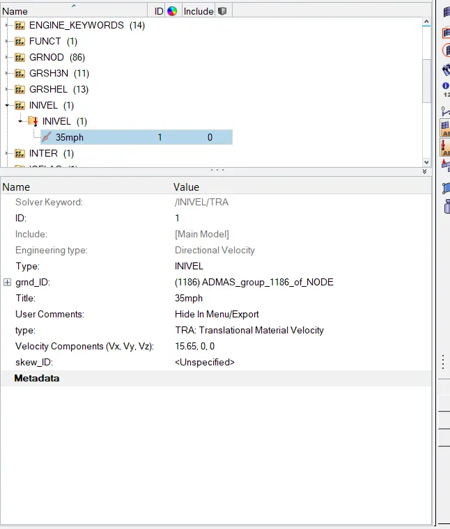
the velocity need to be applied is 35Mph,
since, the units are kg mm ms , thefore the value to input is 15.65mm/ms
Contact interfaces:
Solver > inter
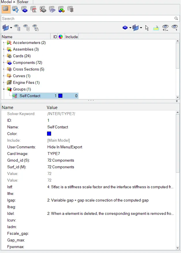
A type7 contact is created between all the components with a friction coefficient of 0.2,
Rigid wall (wall):
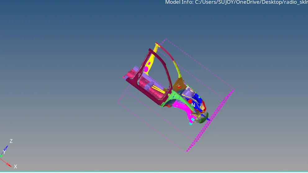
To create a rigid wall at the front side of the car, creat the outermost node at the front of the car. Using temp nodes option.
Then right-click in
solver browser and navigate to Create > RWALL > Plane
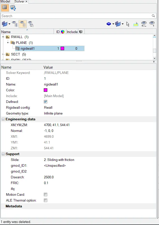
In the RWALL panel, under Engineering data specify the coordinates of the wall.
Select a node at the front bumper and set the at xm, ym, zm by selecing a node and add a normal reaction to the wall as -1 for the reaction.
The FRIC value will be 0.1 and search value will be 2500 as shown below
Cross Section:
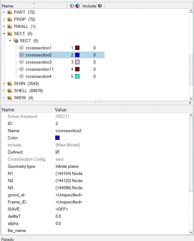
For the required results cross sectional is created which are calculated based on a frame of reference. So before creating cross section,create moving frames on a particular node of that section. Now as the moving frames is created which are also called as local axis, the local axis needs to be aligned to the global axis.
Once the moving frame is created,next step is to create cross-section for the frame. To create a cross-section,right-click on the Solver browser, navigate ,
Create > SECT > SECT
In section panel, specify the Frame_ID.
Right click and create grshel _id on the same panal, select the elements where the cross sectional is required for appropriate results.
Intrusion measuement setup:
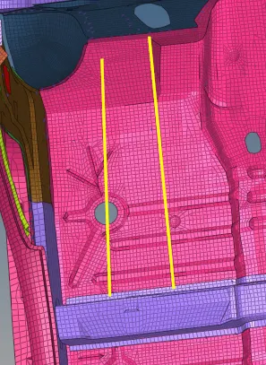
Here, its asked to find the intrusions at node provided with respect to car body. So to find the results at the specified parts, create spring between the node provided and the base cross member of car, for creating spring;
1D > SPRINGS > SPRING2 , select 2 nodes;
Time step and Run time:
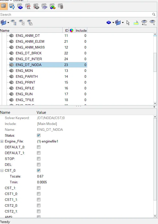
The run time is kept to be 80ms;
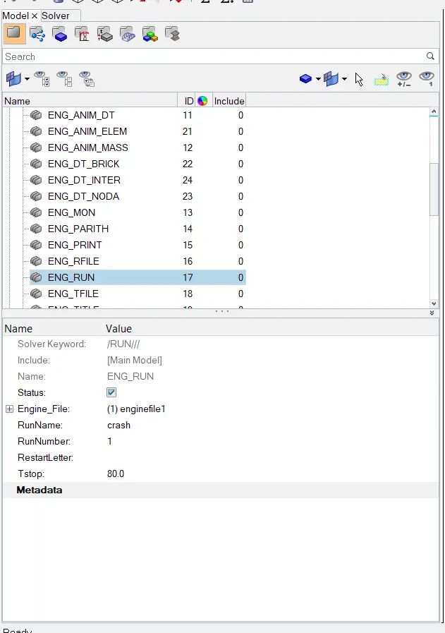
in ENG_DT_NODA, Tmin is kept to be 0.0005 micro second as shown below,
Symulation run:
Now, the model is ready for symilation,
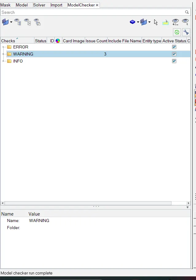
before running the symulation the model is checked using radiossblock , to check ;
Tools > model checker> radio block
once the check is successfully done the model is ready to run for analysis.
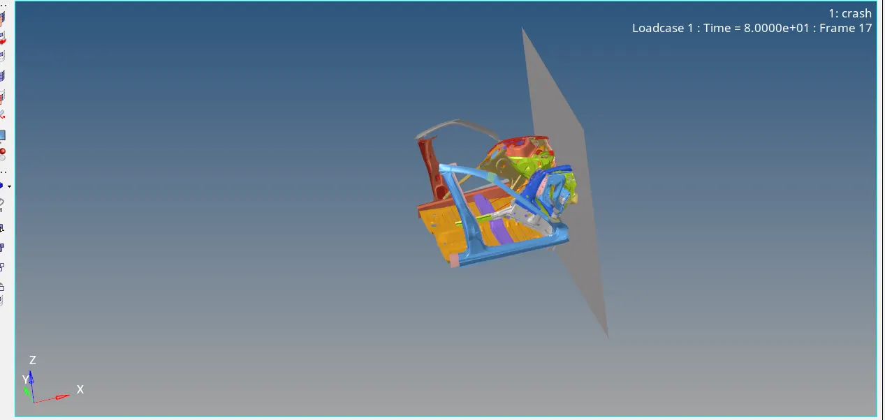
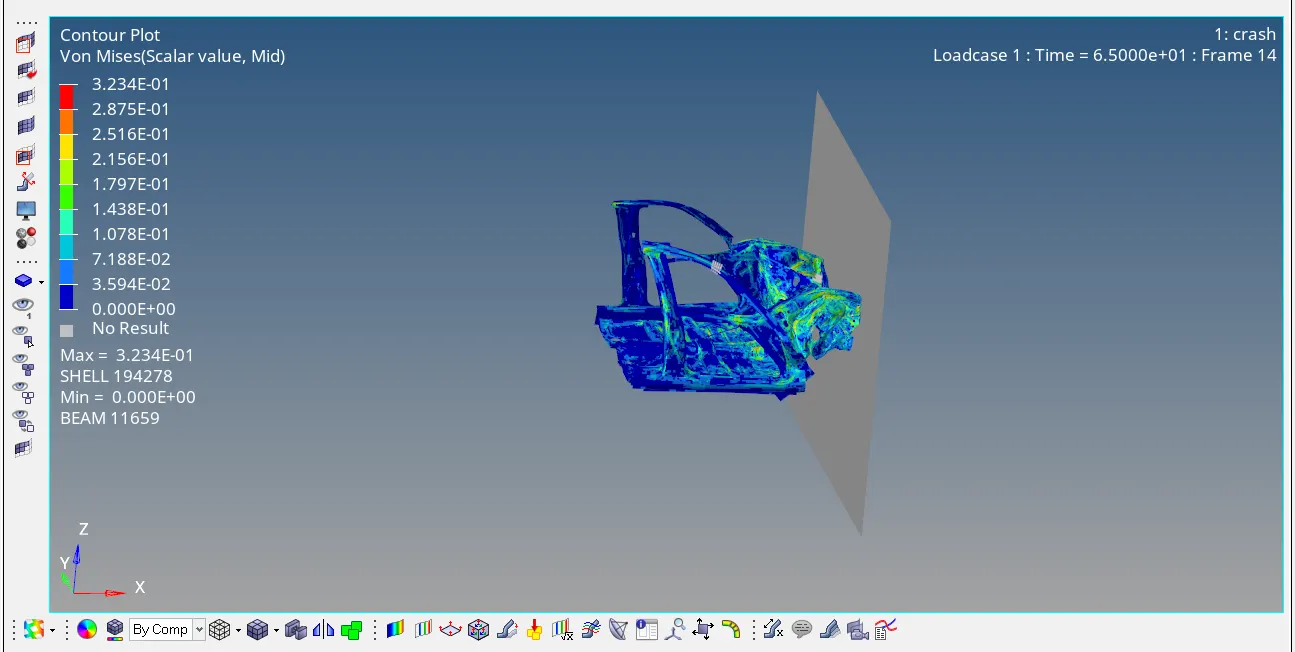
Elapsed time is 1hr 14mins with error as -2.3% . Max stress of 321Mpa is found
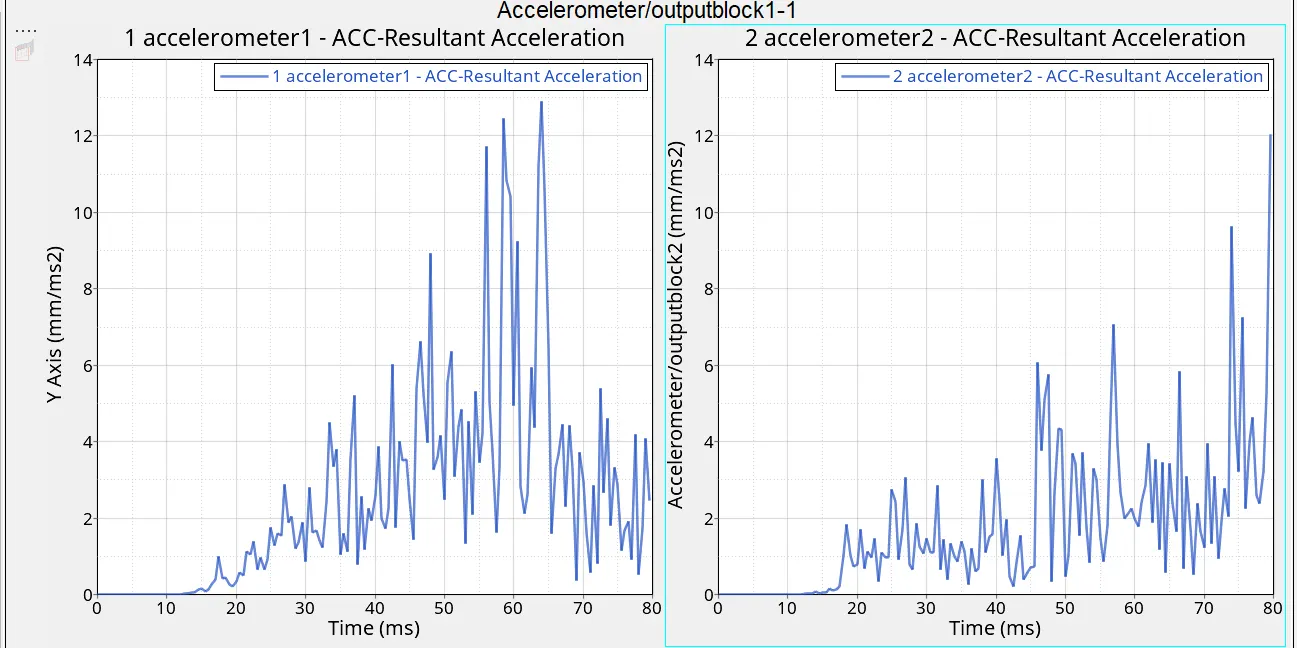
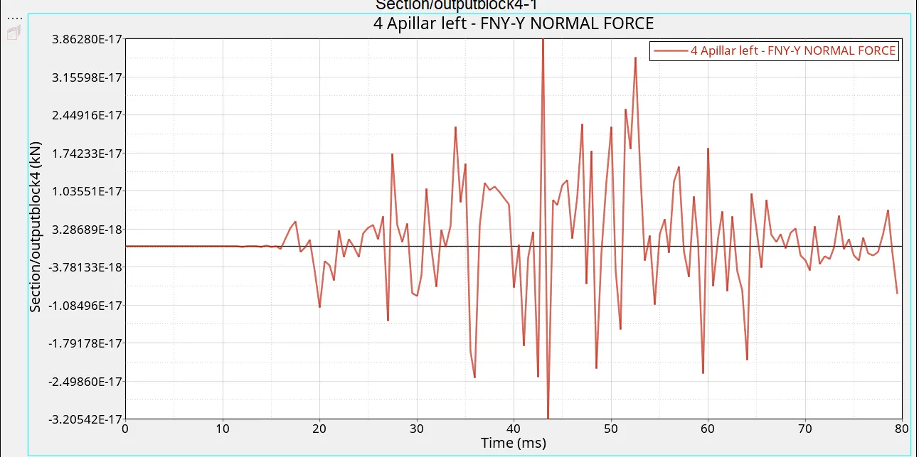
Conclusion:
The given model was simulated for the frontal crash using Radios and the results obtained were validated.The hourglass energy is less than the internal energy. The graphical results were plotted for all the test cases. From the simulation, it can be observed that there was minimum deformation in the cabin, and also minimum intrusion was found in the driver's seat area.