Assignment 6-Frontal Crash Simulation Challenge
- AIM:
The main aim is to perform frontal crash analysis in the neon model with the recommended parameters and output requests.
- Frontal crash-BIW
-
- Check unit system and either follow [Mg mm s] or [Kg mm ms].
- Create appropriate interface, friction 0.2 and recommended parameters.
- Make sure of no penetrations and intersection.
- Correct rigid bodies if any issues.
- Create rigid wall with friction 0.1.
- Compare the model weight with the full scale 300k nodes model and use added masses to reach target weight 700kg while getting CG about the required range.
- Initial velocity 35 mph.
- Use model checker to ensure good quality.
- Time-step :0.5 to 0.1 microseconds.
- Run 80 ms.
-
- Output requests
-
- Sectional force in the rails at location of indicated node 174247.
- Axial force received on the rails from bumper.
- Shotgun cross sectional forces.
- A pillar cross section.
- Acceleration curve received on the accelerometer at base of B pillar (on B pillar rocker).
- Intrusions on the dash wall 66695,66244.
-
- Procedure:
- Pre-Processing: -
-
-
- Open the hyper mesh with user profile as RADIOSS.
- Import the starter file in Radioss.
-
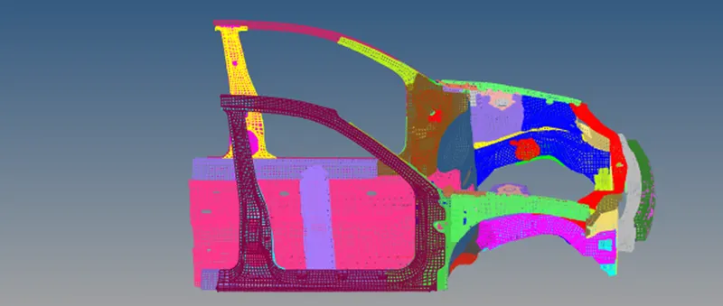
Fig 1: Given Frontal crash vehicle component
-
-
- Check the unit system under begin card. This model has unit system of [Kg mm ms].
-
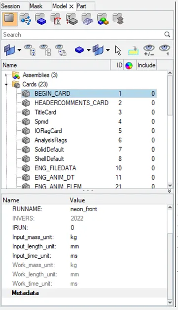
Fig 2: Unit system in begin card
-
-
- Open hyper crash in application menu.
- Go to Quality – contact interface – select type 11.
- Enter the values and click okay.
- Go to load case – contact interface – click check penetration option – select components – click check.
-
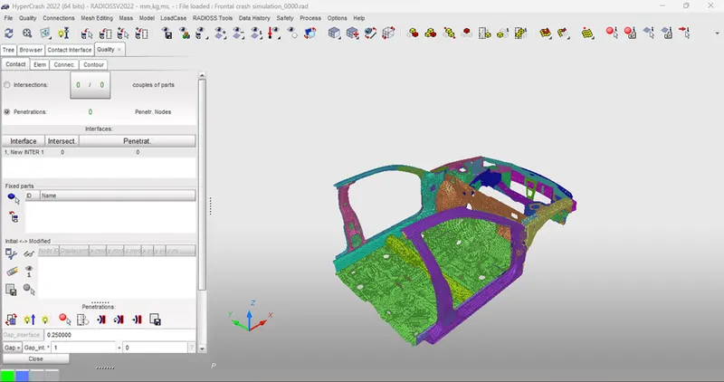
Fig 3: Penetration check
-
-
- Check intersection in the model.
-
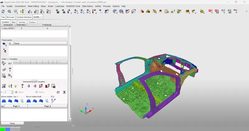
Fig 4: Intersection check
-
-
- In this model, there is no penetration & intersection.
- For this model, initial velocity is 35mph (15.6464 mm/ms).
- In solver desk, right click to create initial velocity.
- Select all components and enter velocity value.
-
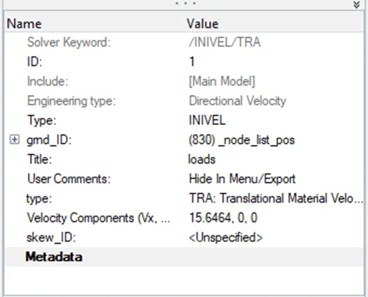
Fig 5: Initial velocity
-
-
- Right click on solver browser to create interface.
- Delete all existing interfaces
- Select Type 7 card and select the slave nodes and master surfaces.
- Define all recommend parameters for type 7 interfaces.
- Enter inacti as 0. Because no penetration in this model.
-
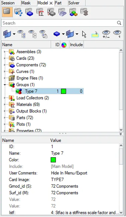
Fig 6: Contact interface
-
-
- To create rigid wall, right click on model tab to create rigid wall.
- For Dsearch as 1000mm & friction as 0.1mm for slave nodes.
-
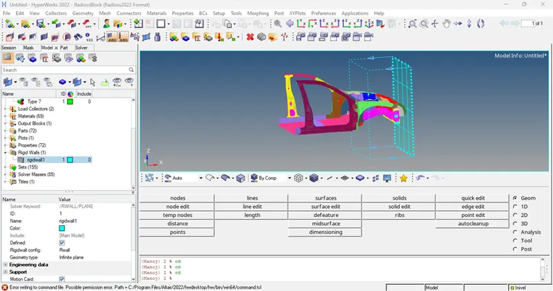
Fig 7: Rigid wall
-
-
- Initial mass of model is 188Kg. represent the mass for full car. Converted mass is 700Kg.
- Right click on solver to create mass. Select ADmas card.
-
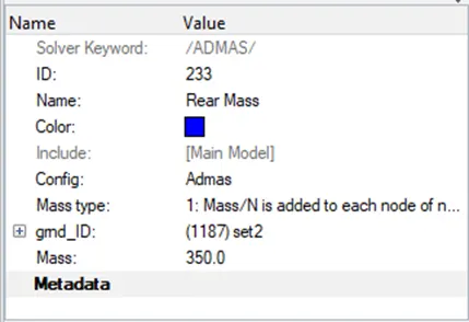
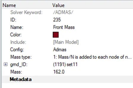
Fig 8: Mass created for model
-
-
- Rear & front mass are created for model.
-
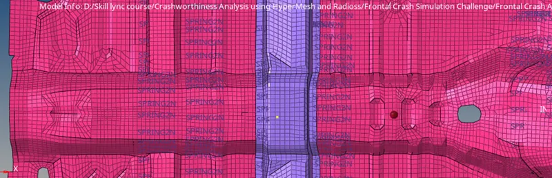
Fig 9: CoG created for model
-
-
- Create cross section for model. Create local co-ordinate same as global co-ordinates.
- Create cross section for A-Pillar, Shot gun, Fender, Bracket & Rail.
- Create for both left & right side of vehicle.
- Go to solver browser, right click to create frame and MOV.
- Select nodes and create local co-ordinates.
- Right click on solver browser – SECT-SECT – Select frame ID – enter delta value as 0.1.
- Enter alpha value as 0.628 and set grshell id.
- Follow same procedure for all frame.
-
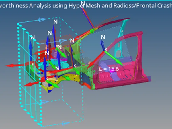
Fig 10: Cross section created
-
-
- To measure the acceleration of B Pillar during the crash. Create accelerometer on both the B Pillars.
- Right click on solver browser – create – Accel.
- Select the node and Specify F_cut as 1.65.
-
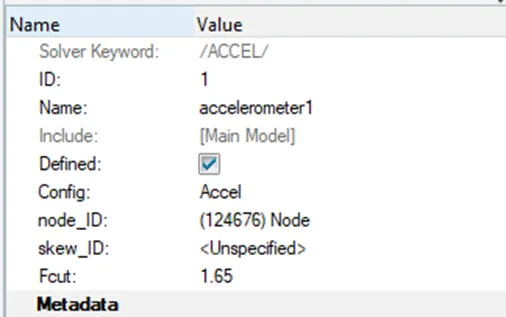
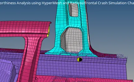
Fig 11: Accelerometer created
-
-
- Repeat the same process for other side.
- To run the simulation, check for error in the model.
- Go to tool – model checker – Radioss Elements.
- Click on run check and click on auto correct is in blue box.
-
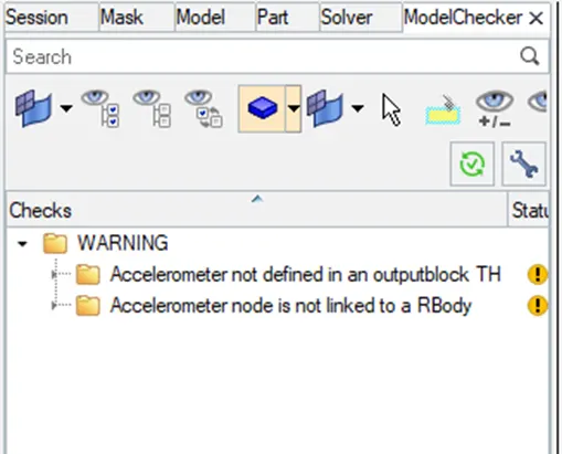
Fig 12: Model checker
-
-
- Above image shows the N1, N2 & N3 are badly defined, can be ignored as the sections are assigned to moving frames which are created separately.
- Other errors and warnings can also be ignored.
-
- Processor: -
-
-
- Now run the simulation. Go to Radioss in analysis.
- Specify the path to save the file and type ‘-nt 4’ In option.
- Click Radioss and run the simulation.
-
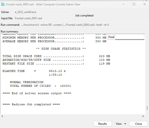
Fig 12: Analysis Done
-
-
- First check for Energy & mass error.
- Open Engine.out file of the model and check the energy & mass error.
-
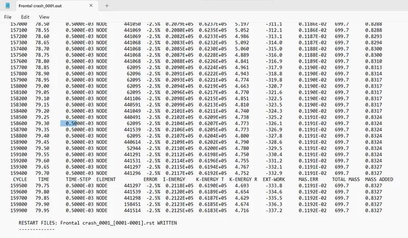
Fig 13: Energy & Mass Error
-
-
- The Energy errorwhich is -2.5% and Mass error which is very negligible. This shows that the energy error and mass error are within acceptable range.
- Total number of cycles used id 160001 and total run time of simulation is 6446.46s.
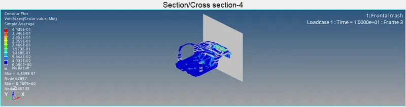
- Open hyperview to view animation and contour plot.
- Select the von misses in result type and simple in averaging method.
-
ENERGIES PLOT: -
-
-
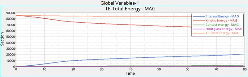
- From the above plot, we can see that there is high amount of Kinetic energy at the start of the simulation but as the simulation progresses, the kinetic energy in the vehicle decreases and gets converted into internal energy, so the internal energy increases in the same proportion.
- Thus, the total energy in the system is almost constant at 85000 J and due to some energy loss, which we can see in energy error, there is some decrease in total energy.
- We can also see some amount of contact energy in the model as we have defined the value of friction in Type 7 interface due to which contact energy is generated.
-
CROSS SECTION - 01: -
CROSS SECTION - 02: -
CROSS SECTION - 03: -
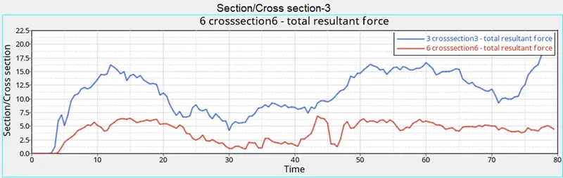
CROSS SECTION - 04: -
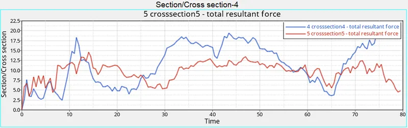
INTRUSION: -
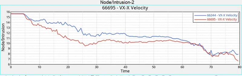
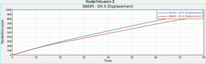
At 66244 & 66695 node location, the intruded force is at its peak due to the absence of components of a car. If the components are present, they will absorb the forces and the rest will be impacted on the dash wall.
Accelerometer: -
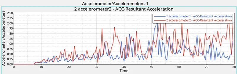
The left accelerometer placed at the left side has high acceleration compared to right side.
Conclusion:
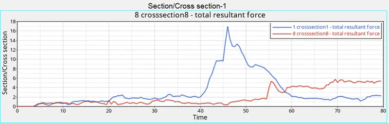
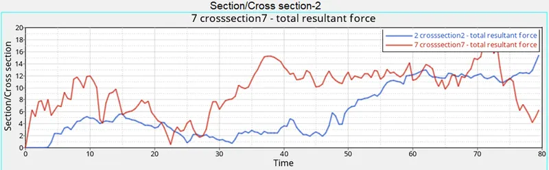
Thus, frontal crash has been analysed on the neon model and the observation are analysed and recorded. On studying the results, the forces absorbed are high in the order from Shotgun, Rail, Fender and A-Pillar respectively. These results are not most accurate even though the mass is balanced & COG is located at its exact position. If we want more accurate results, it is advised to use full scale neon model for the simulation.