Assignment 6-Frontal Crash Simulation Challenge
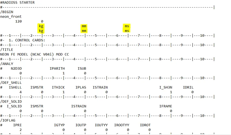
- The unit system can be check open file Neon_front_0000.rad in notepad. We can see that the unit are in kg mm ms.
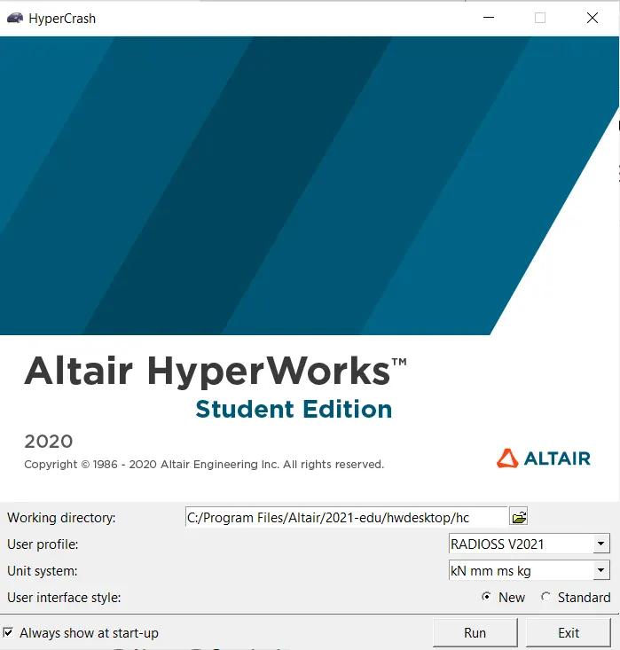
- Open hypermesh>go to application>HyperCrash
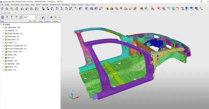
- Once HyperCrash is opened import the model. After importing the model checking penetration and intersection.
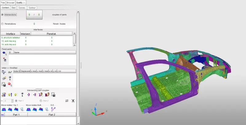
- Go to>Quality>Check intersection on tree>Click on check interface.
- Using added mass option in the hypercrash additional mass is added for the passenger, driver and trunk portion of the car and the total mass is about 700kg is achieved and the COG point is placed properly.
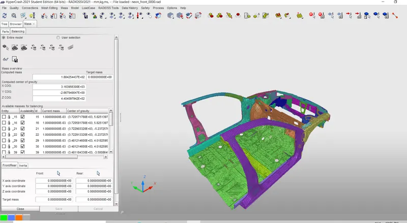
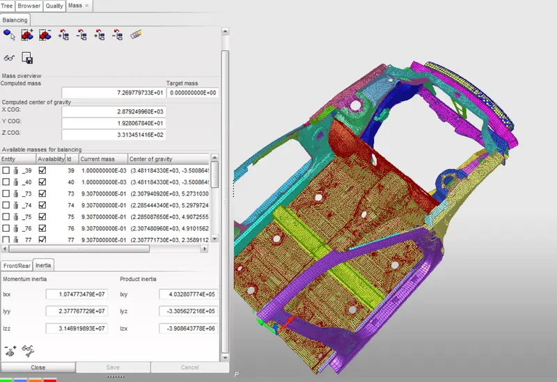
- Now we can see the below image the COG is align at the centre and the mass of the car is not exceeding 700kg.
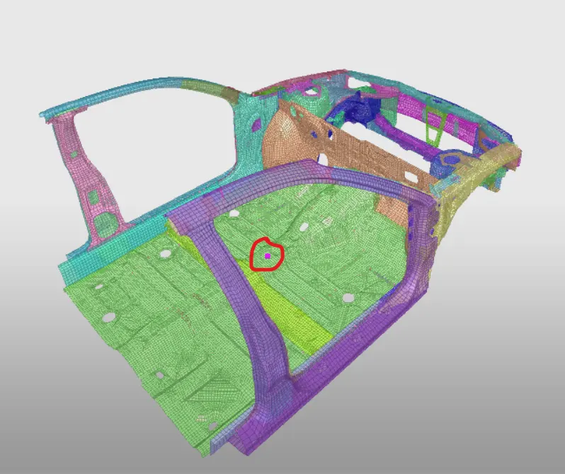
- After that model is exported into the Hypermesh using the export option.
- Go to>file>export>Radioss
- Now import the same file in hypermesh to do other changes.
CONTACT INTERFACE:-
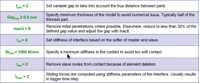
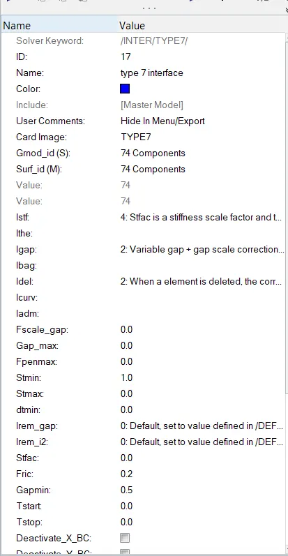
- Type 7 node to surface contact is used in this model both the slave nodes and the master nodes will be the same for this simulation since there is self-intersection between the parts while it simulates.
The recommended properties are as following-
CONTACT INTERFACE BETWEEN THE BUMPER AND THE HEADLIGHT BRACKETS:-
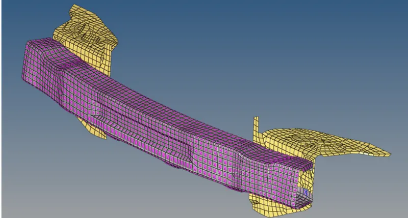
- This interface is done to calculate the force transfer in this region. The slave nodes will be the bumper and the master nodes will be the brackets. Other than these changes rest of the properties will be the same as in the previous case.
RIGID WALL:-
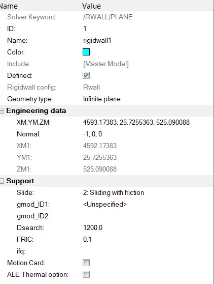
- Arigid wall is a nodel constraint applied to a set of slave nodes in order to avoide the node penetration to the wall. If contact is detected, then the slave node acceleration and velocity are modified. Mainly to constrain the movement of a moving body after impact, we will be using a plane wall. An infinite plane wall is a plane that extends to infinite. It is defined with two points.
- Rigid wall entities provide a method for treating a contact between a rigid surface and nodel points of a deformable body. In the Radioss user profiles, rigid walls can be created in the model and solwer browsers. To create an RWALL-
GO TO SOLVER BROWSER>CREATE>RWALL>PLANE-
- We need a reference node to create an RWALL so we can select a node at the center of the bumper.
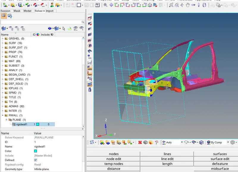
- Based on the reference node we can adjust the wall in such a way that it is not in contact with the car and there is a small gap between the wall and the vehicle.
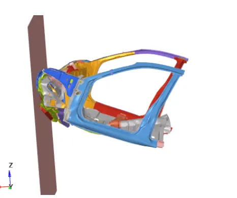
- Make sure the normal of the RIGIDWALL is facing the vehicle as shown in the above image. We will be providing the contact interface as sliding with friction with a frictional coefficient of 0.1.
- The D-search distance we can use around the range of 1200 mm. All the nodes within this distance will be considered as slave nodes for the contact between the car and the rigid wall.
INPUT VELOCITY:-
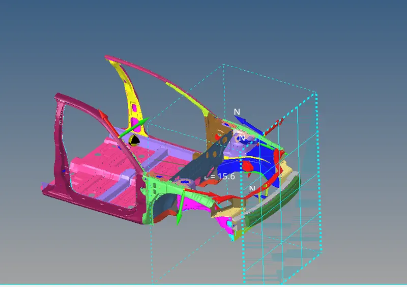
- The velocity input for this simulation as per the standard is 35 mph so when we convert in into m/s the input velocity is 15.646 m/s. To create a velocity.
GO TO SOLVER BROWSER>CREATE>>BOUNDARY CONDITION (BC)>>>INIVEL
- Define the node group on which specified initial velocities are applied (grnd_ID1). For our simulation, we will be selecting the whole vehicle setup.
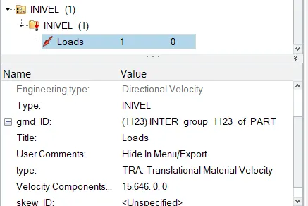
- The velocity type is selected Translation velocity and it is provided in the x-direction as shown in the above image.
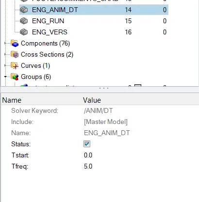
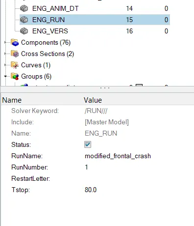
TIME-STEP:- 0.5 to 0.1 microseconds and run 80 ms.
CREATING SECTIONS:-
- We will be creating sections at A-Pillar,Shot Gun, Rails and the Bumper in order to study the sectional forces. We have to know how the forces are transmitted fro the bumper to the dashboard and the rate of deformation. I t is done in order to ensure the safety of the passenger.
- Certain components have to deform more than the other so that the forces are distributed correctly leaving very littke forces left to transmit inside the cabin.
- To create sections-
GO TO SOLVER BROWSER>CREATE>>SECTION>>>SEC
CREATE ACCELERATION NODES-
- Creating Accelerometer at both sides of the B pillar.
- An accelerometer is a basic technology that converts mechanical motion into an electrical signal. It is an electromechanical device that measures acceleration forces, wheather caused by gravity or motion. To create accelerometer-
GO TO MODEL BROWSER> CREATE>>ACCELEROMETER>>>SELECT NODE_ID>>>> SELECT NODE>>>>>PROCEED
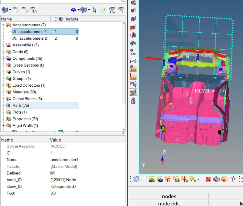
- Make sure to create a time history file for these accelerometer individually so that we can view the intrusions.
CREATING SPRINGS-
- We are planting spring elements to study the intrusions (forces inside the cabin causing deformation/rupture). Create two parallel spring elements from the indicated nodes (66695, 66244) till the crossbeam.
GO TO 1D PAGE>SPRINGS>>SELECT FIRST AND SECOND NODE>>>CREATE SPRING
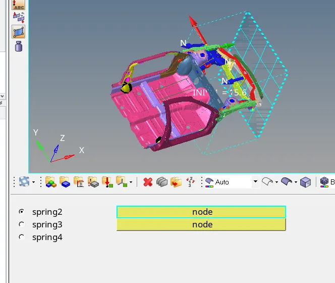
CREATE PROPERTIES FOR SPRINGS-
GO TO MODEL BROWSER> CREATE>PROPERTY

CHECK:-
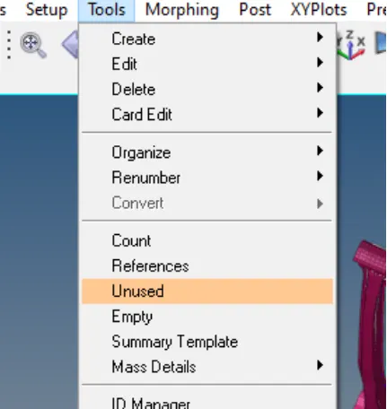
- These checks can be done via both hypermesh and hypercrash but it is recommended to check via the hypercrash module. Before exporting the model we will be cheking for unused and empty, also make sure all the parts are connected or ince the simulation is done the results will be wrong with parts flying.
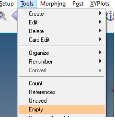
- Tools>Unused and Tool>>Empty and delete the unwanted data in the model and export them.
- Also delete the empty card as well.
NOW RUN THE SIMULATION
- Go to the Analysis>Radioss
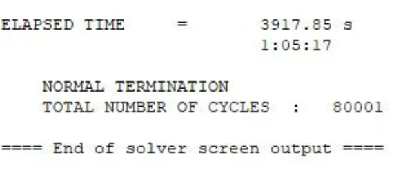
- To show h3d file open hyperview.
ENGINE OUTPUT FILE:-
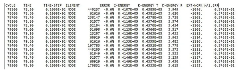
- As we can see, the energy error is -0.6%. It is definitely acceptable within range of -10% to +5% error. In addition to that the mass error is 0.03213, which means that a negligible quantity of mass of wass added during the simulation, possibly for the sake of time step control/stablization. It is a rather low amount so it's still acceptable.
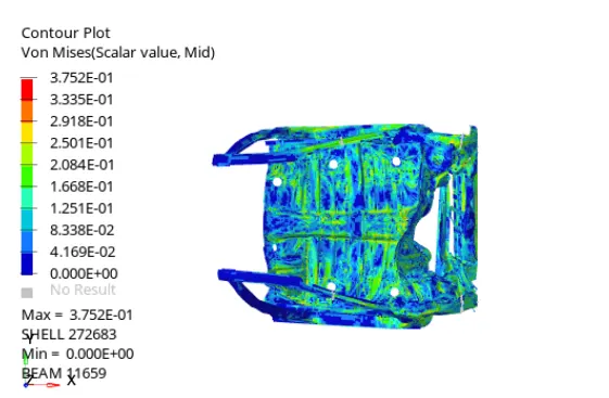
- For the Von Mises stress plot, we can say that the stress distribution is quite good in the vehicle after the crash. There are very few areas where we can see stress concentration. Generally, the stress is more in bumper region as it is the first point of impact.
PLOTTING GRAPHS:-
- Open T01 file in HyperGraph 2D.
- The graphs of request output as shown below-
RAILS 1 AND 2
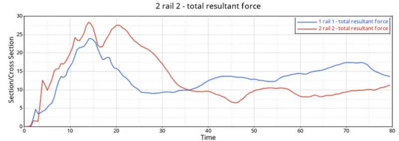
- Here you can see the peak time of the both sections is same but the c/s of rails 2 having resultant force is 27kn/mm is more that rail 1 having resultant force is 24 kn/mm.
BUMPER 1 AND 2
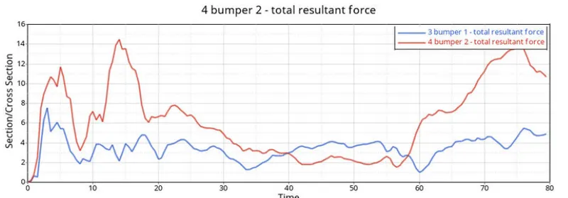
- Here the peak time of first bumper is near about 5ms total resulatnt force is 8kn and the peak time of bumper 2 is 15ms with total resultant force is 14kn.
SHOTGUN 1 AND 2
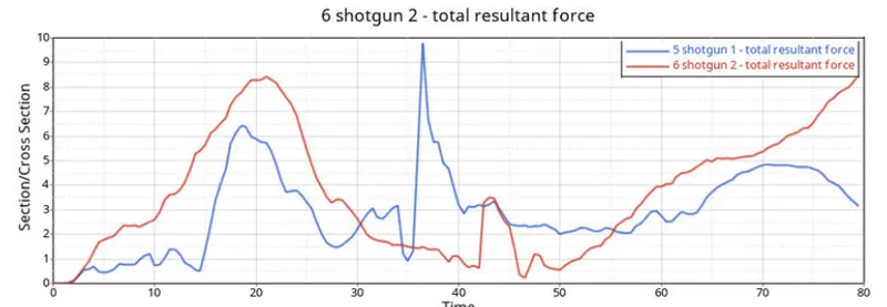
- The force in the short gun (section 2) is more linear compared to the sharp hills in the left short gun (section 1).
- The maximum cross-sectional total resultant force at shotgun 1 is 10 kn/mm at t=38ms where as the maximum cross-sectional total resultant force at shotgun 2 is 8.5kn.mm at t=23ms.
PILLAR 1 AND 2
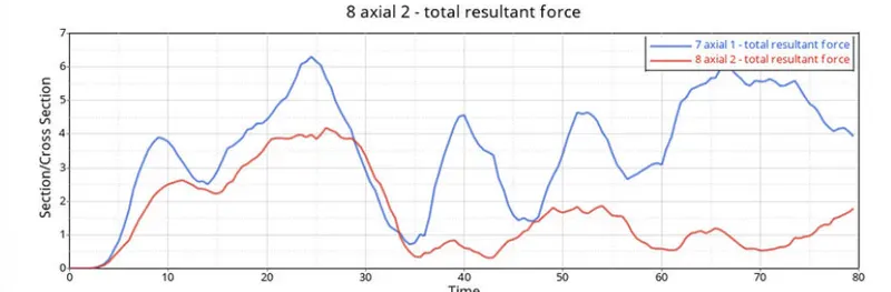
- Pillar has maximum total resultant force of 6.2KN where as pillar 2 has maximum total resultant force of 4KN. Hence, the normal forces are not significant.
ACCELARATION
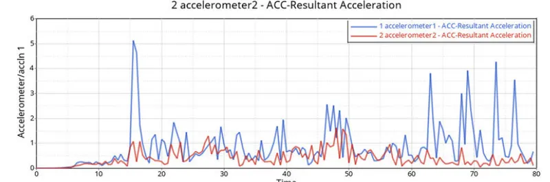
- Accelaration of the 1st point is more fluctuating that the 2nd.
INTRUSION 1 AND 2
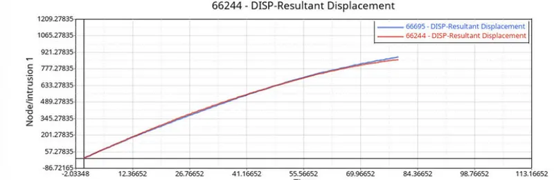
- Both the resultant displacement is same.
RWALL
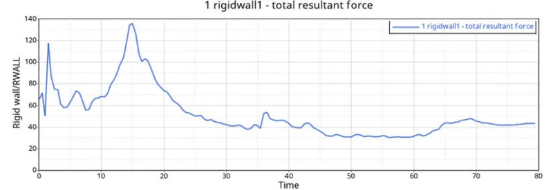
- The peak point shown where the car hot on the wall at maximum force which is 140KN at 15ms.
INTERFACE
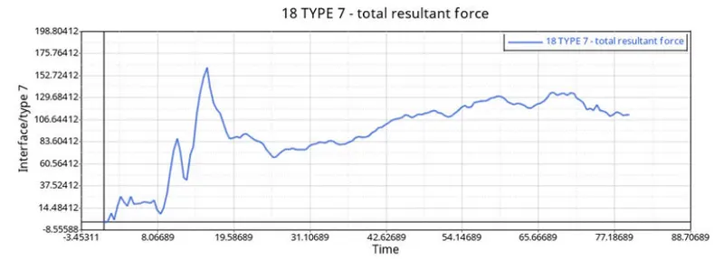
OUTCOMES:-
- Able to balance the mass of the component.
- Able tp create initial velocity, accelerometers, intrusions, frames sections and local co-ordinates.
- Created time history cards and output block.
- Rectified errors in model checker.