FRONTAL CRASH ANALYSIS
AIM:To perform a frontal crash analysis on a neon BIW with a given test protocols also perform the simulation with the insertion of given data in the given model.
PROCEDURE:(A) Let us begin with the checking of unit system of the model given before that we got to see the model in which all the operations are being performed both are stated below:
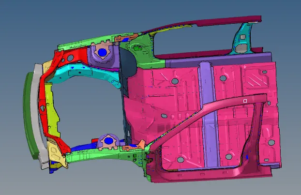
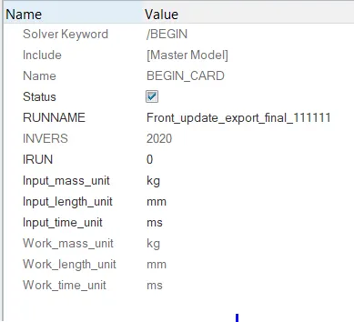
The above image we have got from the Cards in model section under BEGIN_CARDS.
(B)Now in order to create the interface with standards values we can use hyperworks or hypercrash either is fine ,if we have used hyperworks we have to create in solver deck >INTER>TYPE7,if we have used hypercrash we will get in Create new>A-C>contact interface>Type7.Now the standard changes which have been done is shown below in interface:
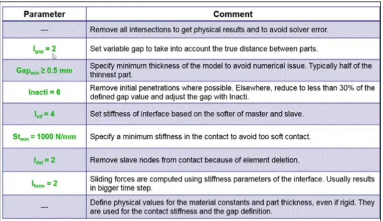
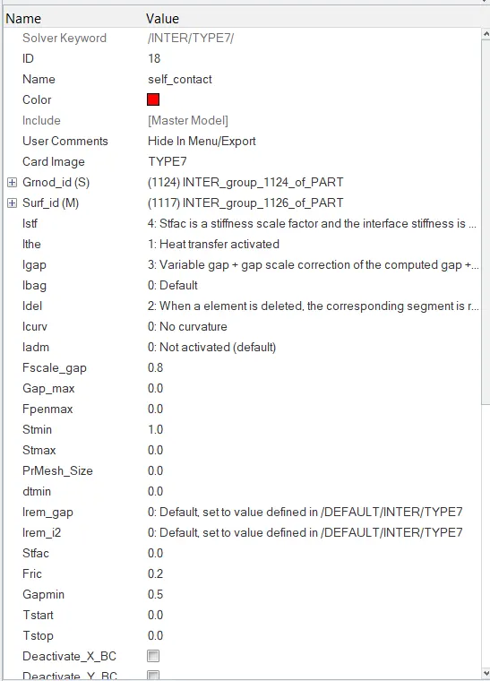
Friction is 0.2 which is given to us as shown above in the images ,Since this is the case of self contact we need to have the whole model for consideration.
(c)Now we got to check whether model having any penetration or intersection if it is having then its's mandatory to eradicate those .Here in Hypercrash Quality>Check all solver contact interfaces we can check for tree for that we have to choose Quality>Check intersection of tree selection but before that we have choose the model under tree,image shown shows the details of intersection/penetration.
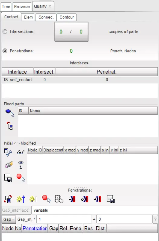
After having the interface we gotta remove all the unneccessary interfaces respectively.
(C)In order to have a Rigid wall we can use both ,in hyperworks Sover deck>CREATE>RWALL>PLANE and in hypercrash CREATE>M-R>RIGID WALL>PLANE.
Something shown below with the given details of RWALL which is being asked.Make sure in the Dsearch the value should be 1000 ,in usual way several slaves nodes of a particuar component do not have multiple masters so if we go to assign it so it is going to show the error called incompatible kinematic condition error and due to this energy might be having an error upto -99% which cannot be considered in any cost so here the term get introduce in it called Dsearch which assign the slave node which are less stiffer in common terms.
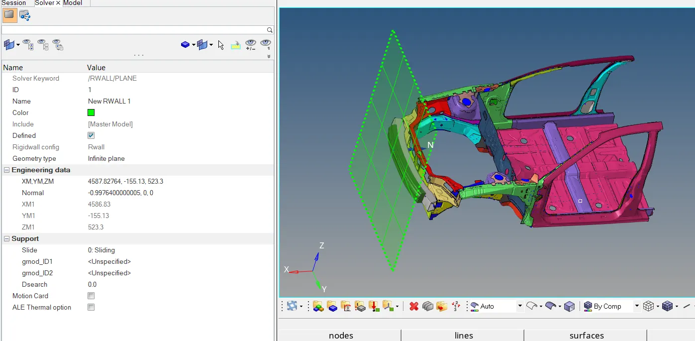
(D)Now in order to compare the full scale model with the working model.firstly lets take a look to full model shown below:
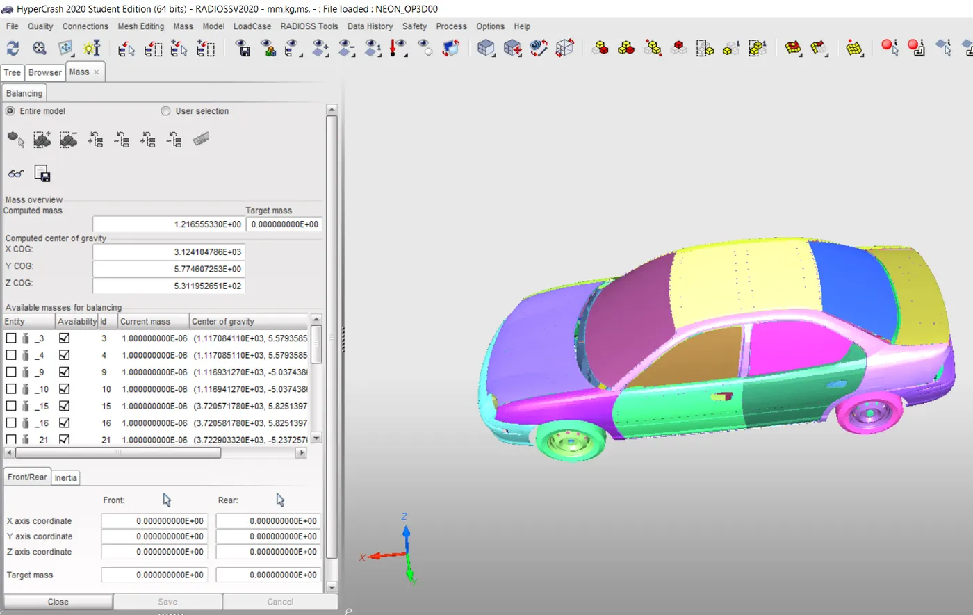
Under mass>balancing we can see the full weight of the model which is 1216.55kg.
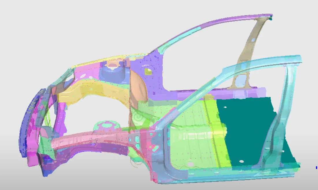
Now the working model having a weight without balancing is shown below:
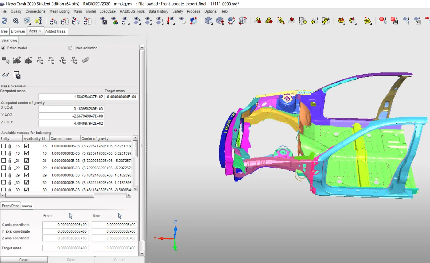
Now we have the model having a weight of 188.4kg we need to balance it and making to it 700kg for that under loadcase>added mass we have to add the mass at the rear part of the working model so that CG get shifted towards the driver seat part because it seams that most of the weight have been concentrated in that particular region.Precisely shown below:
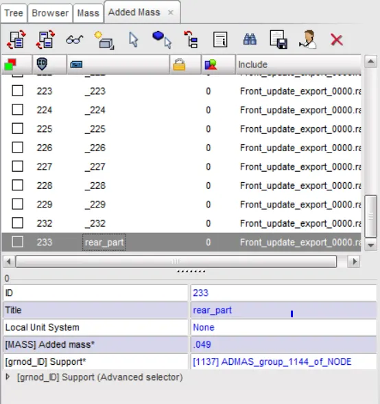
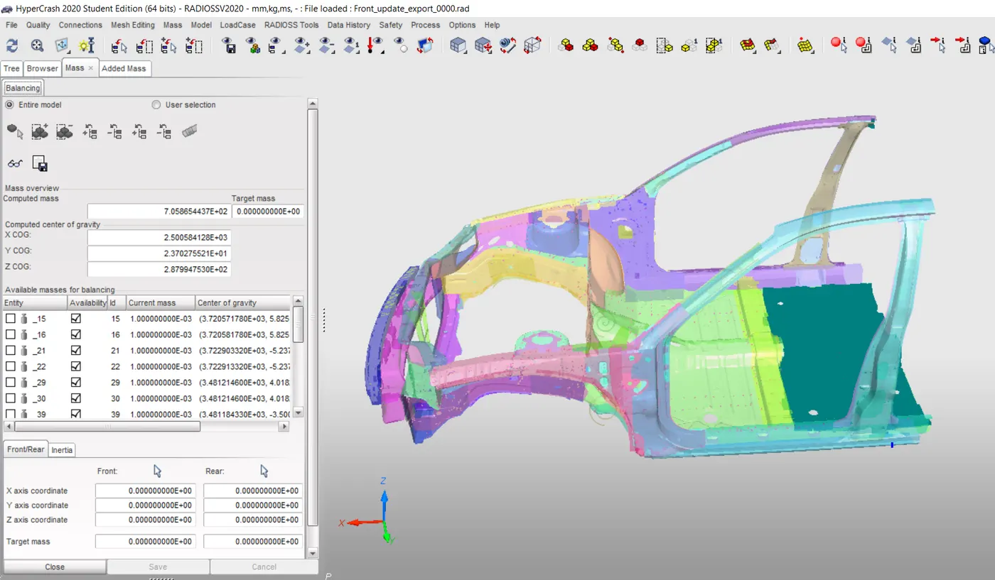
So after adding the mass in the rear part the total mass can easily be visible which is a reuired one.
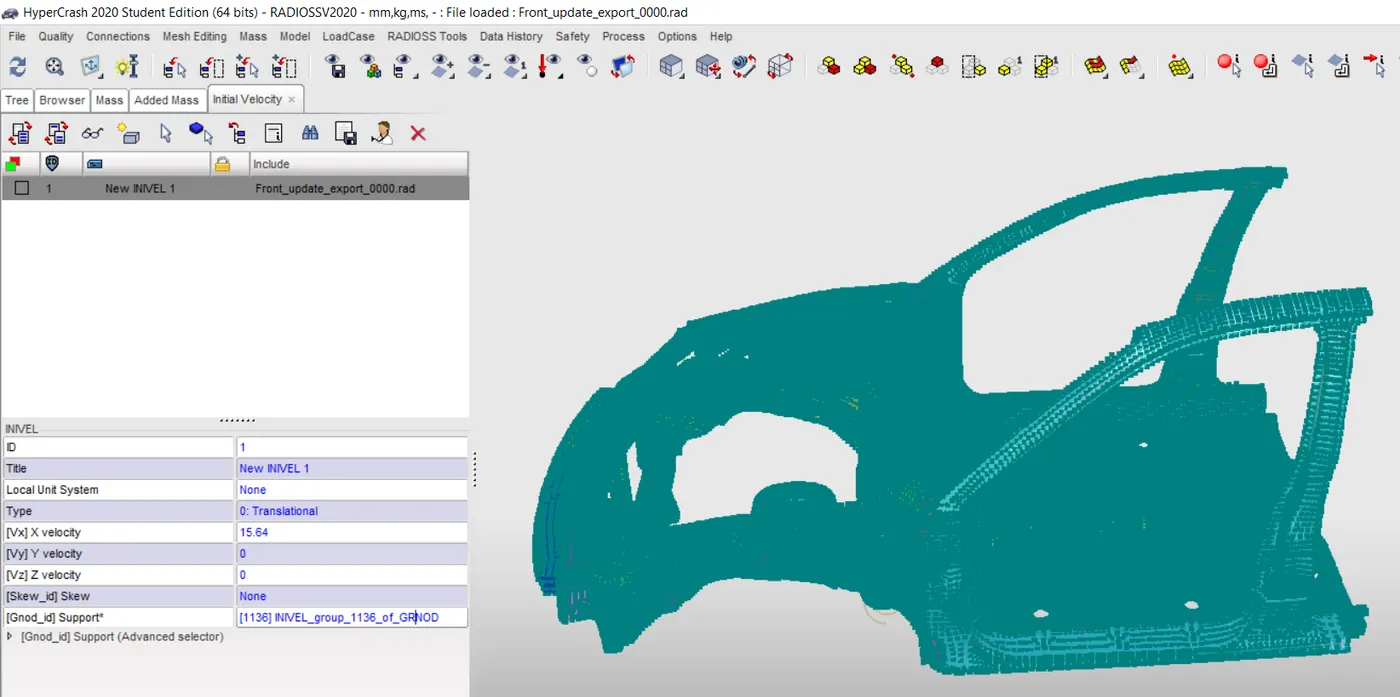
(E)Now after completion of the following steps we gotta add initial velocity,LOAD CASE.INITIAL VELOCITY ,now we have the velocity is 35mph which is being converted into mm/ms i.e 15.64mm/ms.As shown below.
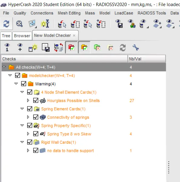
(F)Proceeding ahead to see model checker to remove all the error and make the model should be error free before introducing it in the simulation.In hypercrash we go to QUALITY>NEW MODEL CHECKER and run, the error is being eradicated firstly imposing autofix tool and then if some error could not eliminated can be done by directly deleting it.Following such details we have the result Shown image below:
(G)Now time has came to introduce output request are as follows:
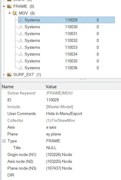
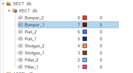
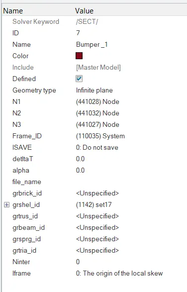
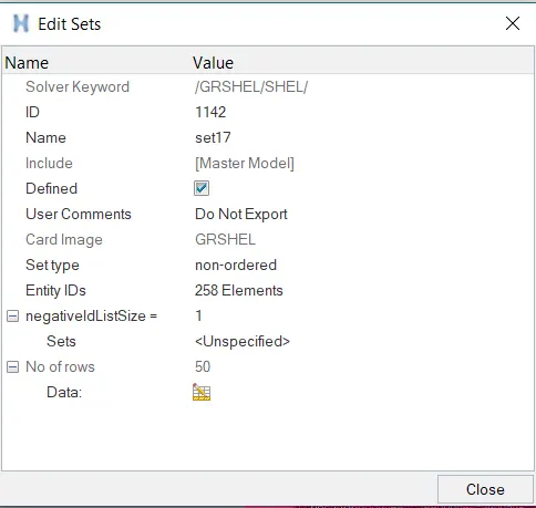
(i)Creation of section in hypermesh CREATE>SECT by doing so we have created it after that we got to create a frame CREATE>FRAME>MOV ,from this N1,N2,N3 will be taken and being put to section,then in section we have Frame id in which we have to select the id which is being created ,now in section we have the option grshell_id we have to create it assigning the entity_id.Showing image gives the clarification we have to create likewise 8 section with 8 frame.
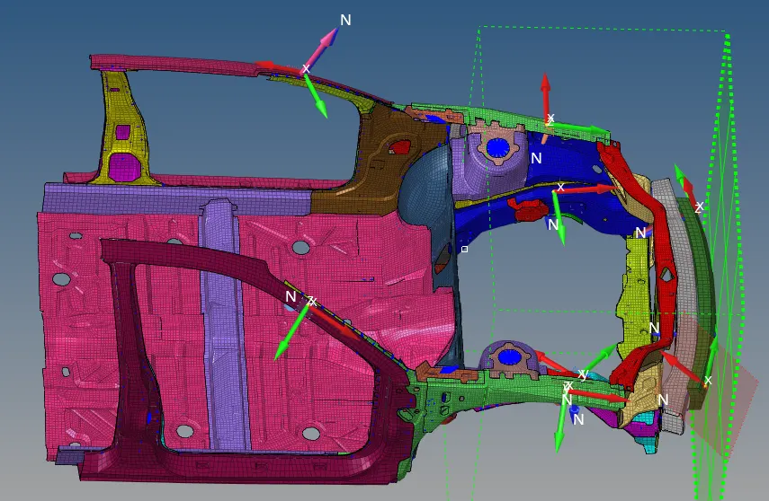
After doing so the section has got created which shown below in the model:
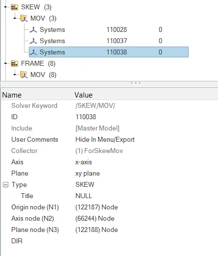
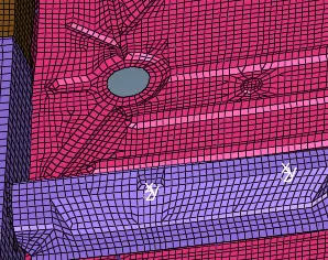
(ii)After to it we proceed to create skew again CREATE>SKEW>MOV.Skew is need to create for the intrusion to the given node 66695,66244.
(iii)Now the comes the accelarometer,CREATE>ACCEL.
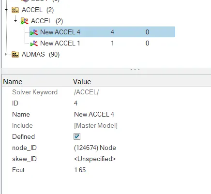
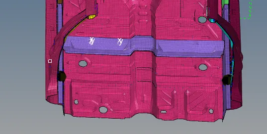
Now after completion of such steps we have to call those things for simulation for that under MODEL we have OUTPUT BLOCK we gotta recall those things.
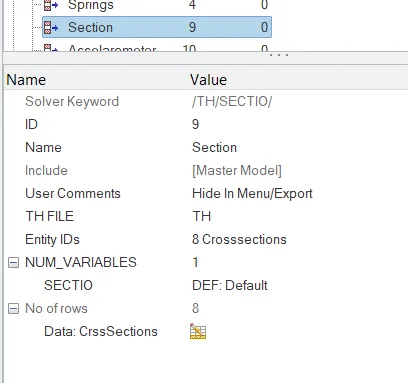
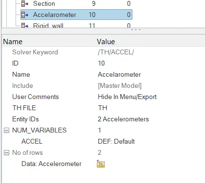
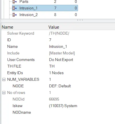
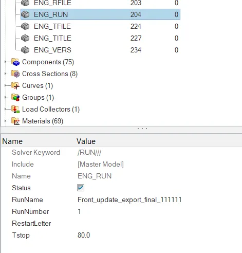
Also the run time is 80ms.
(H)After doing all the neccessary procedure we gotta go for RAD OUT file of 0001 to take a look to various things which shown below and defined below:
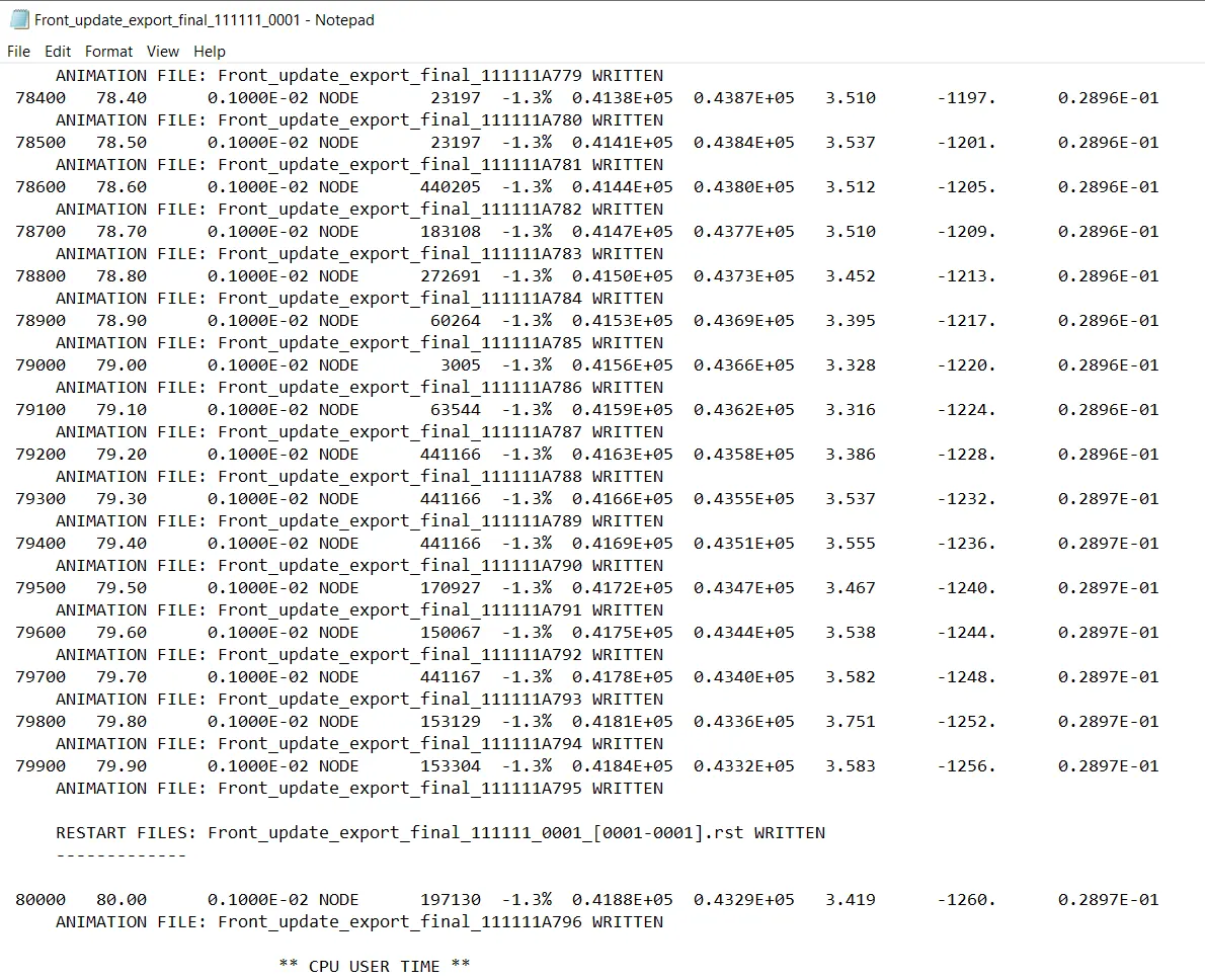
(a)No.of cycles=80001
(b)Elapse Time=7310.07sec/2:01:50hrs
(c)ENERGY ERROR=-1.3%
(d)MASS ERROR=0.2897E-01
So the simulation is taken for consideration as tells that energy error are acceptable it lies in between the -15%-5%
(I)Shifting the mode towards the hyperview in order to have a h3d file for animation point of view:
Shift to contour mode:
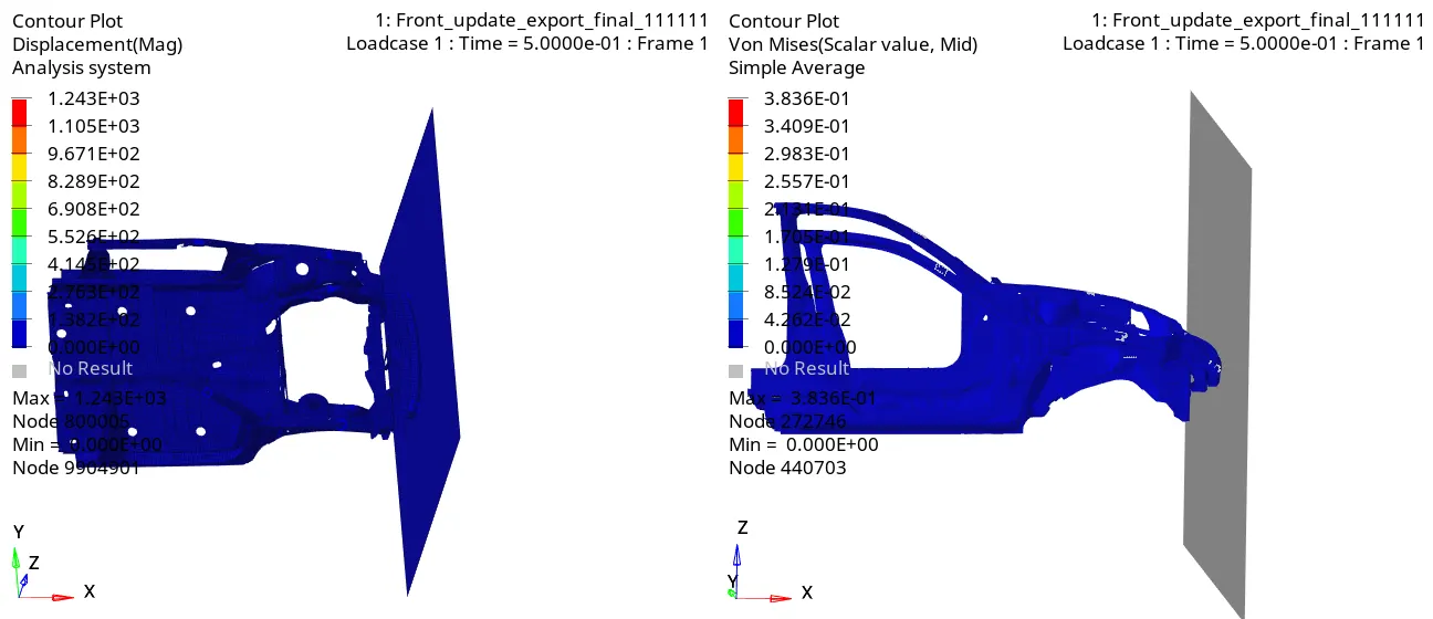
Here we can see 1243mm is going to be the maximum displacement and the maximum von mises stress is 383MPa.
(J)Now shifting the mode towards the hypergraph 2D to get the graphical representation of the various criterion that we have got as shown below:
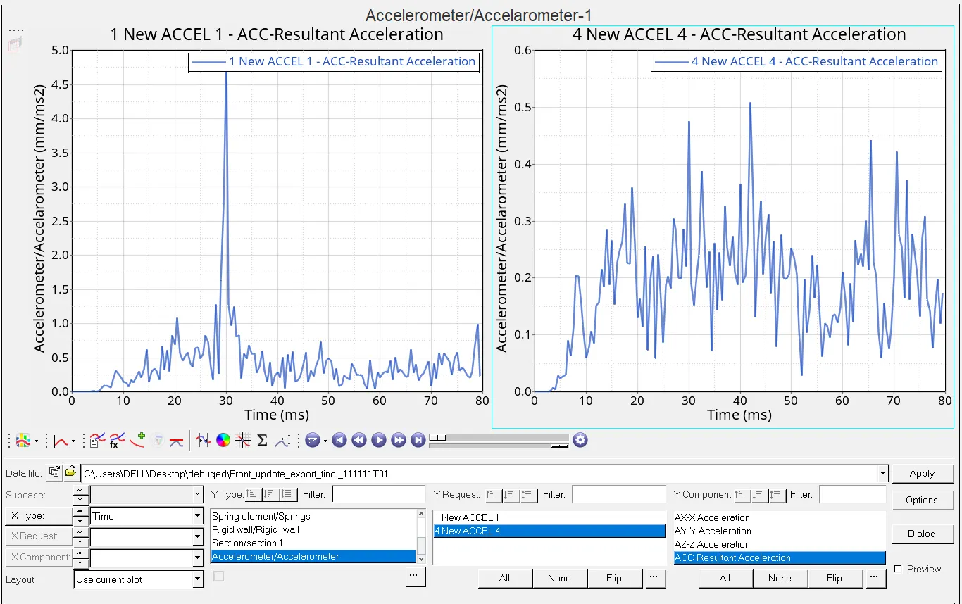
The first graph i.e 1new accel 1 is right pillar accelaration and next to it is the left pillar accelaration.In the first maximum accelaration is almost 5mm/ms^2 and in the second one is 0.55mm/ms^2 so this accelaration variation shows during crashing ,accelarometer which have been put on either sides of the pillar.
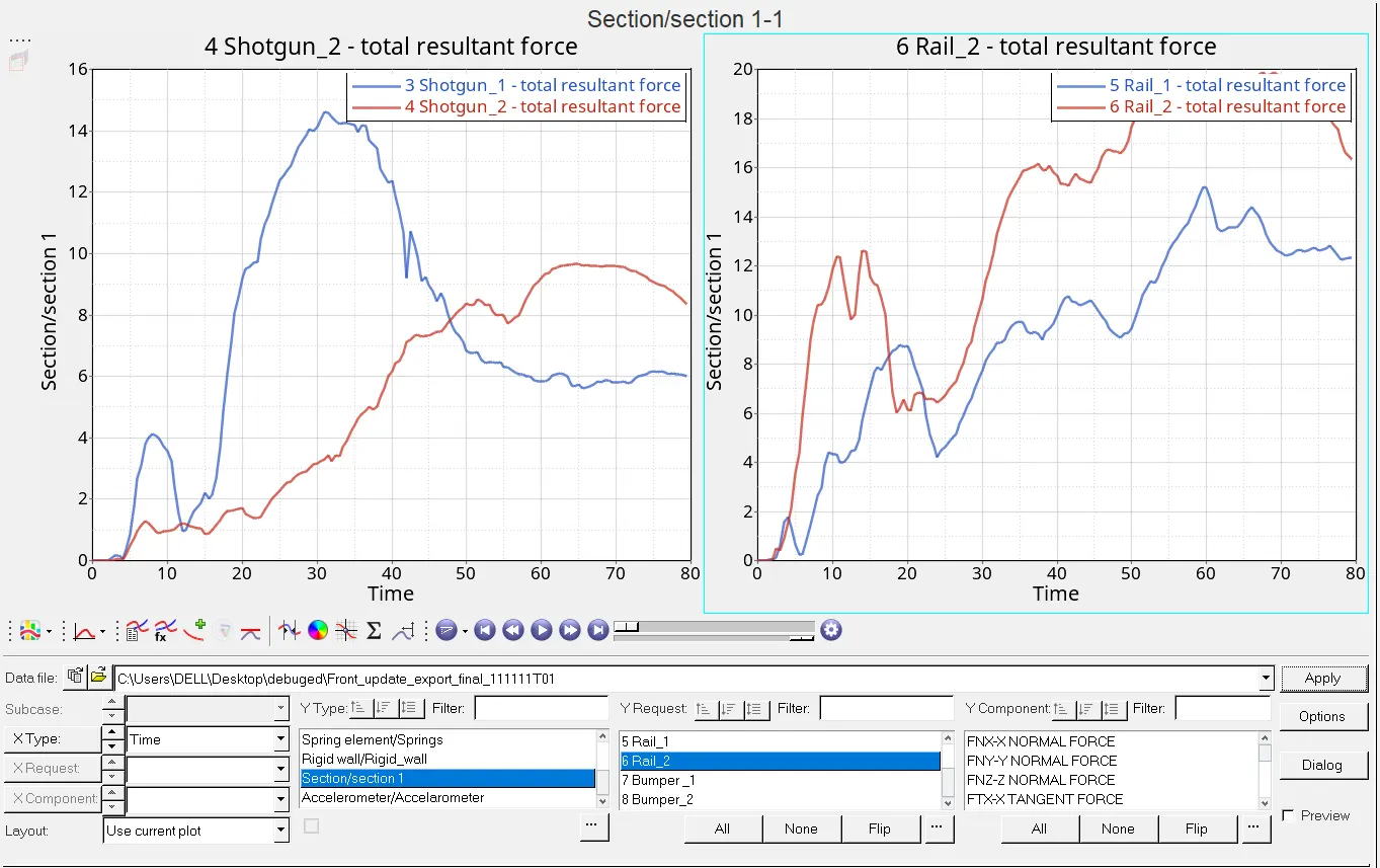
Moving to the section representation in which we have pillar,shotgun,bumper which are also situated in the either sides of assembly and the graph shows the during impact what could be the total resultant force on it.
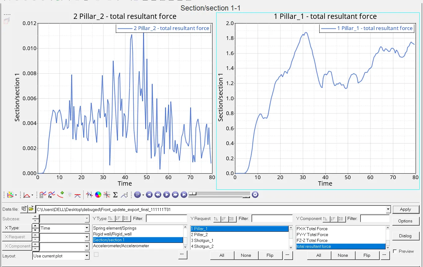
The impact of force is much more in the pillar 1 as compared to pillar 2, in the first i.e pillar_1 max force is 1.9KN AND in the pillar_2 is 0.012KN and the force exceeds to it will proceed to the next part of assembly to get bear off.Similarly the graphs shows are as follows:

The next graph that we have for the intrusion is nothing but the uninvited interuption,here it is measured in terms of displacement of the dash wall towards the stiffer wall and form the deformation as shown below in terms of intrusion1 and intrusion2 which is based on the points considered in the assembly.
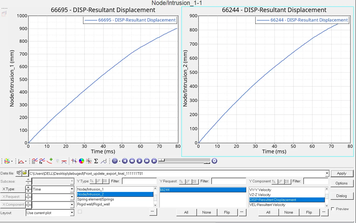
So these are points taken inside the dash wall which shows there own distortion behaviour with max. displacement of intrusion_1 is 900mm and beside to is intrusion_2 is somewhat 850mm. of displacement we don't find much variation because the points are very close to each other.
Let us take the enregy variation into account:
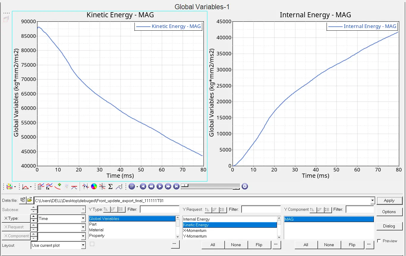
So let us take these energy ,so it is very obvious to know that KE will be decreased due to collision of assembly which signifies in the graph because impact causing kE to get transfered into IE ,it is simple phenomenon steady flow of energy equation ,here there is no heat transfer ,no potential drop but yes it do have work output ,so it can be said KE gets transfered in IE and workoutput.So here max value of KE is 8700KN-mm and IE 4200KN-mm.
CONCLUSION:(a)Here we have got to know about the energy phenomenon how it works in the section of pillar,bumper,rails and shotgun and how much it bear and how much it transfered it.
(b)Also knew about the intrusion and accelarometer works along with where it has to put to get the output.