Frontal Crash Analysis of a BIW model of car using Radioss
Frontal Crash Analysis of a BIW model car using Radioss
Aim:
Aim of this project is to check and create the properties for a neon frontal crash model.
These are the recommended checks performed in the model:-
1. Check unit system and either follow[Mg mm s] or [Kg mm ms].
2.Create appropriate interface ,friction 0.2 and recommended parameters.
3.Make sure of no penetrations and intersection.
4.Correct rigid bodies if any issues.
5.Create rigid wall with friction 0.1.
6.Compare the model weight with the full scale 300k nodes model and use added masses to reach target weight 700kg while getting CG about the required range.
7.Initial velocity 35 mph.
8.Use model checker to ensure good quality.
9.Timestep :0.5 to 0.1 microseconds.
10.Run 80ms.
Procedure:
1. Check unit system and either follow[Mg mm s] or [Kg mm ms].

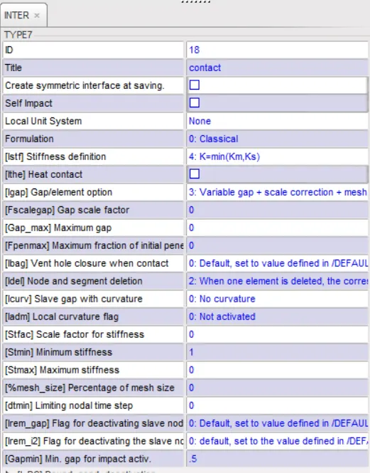
2. Create appropriate interface ,friction 0.2 and recommended parameters.
Interface of type 7 is used to define a proper interface contact for crash analysis.
Interface TYPE7 is a multi-usage impact interface, modeling contact between a master surface and a group of slave nodes.
A coloumb friction of 0.2 is also provided.
3. Make sure of no penetrations and intersection.
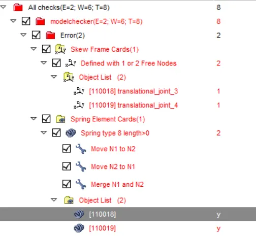
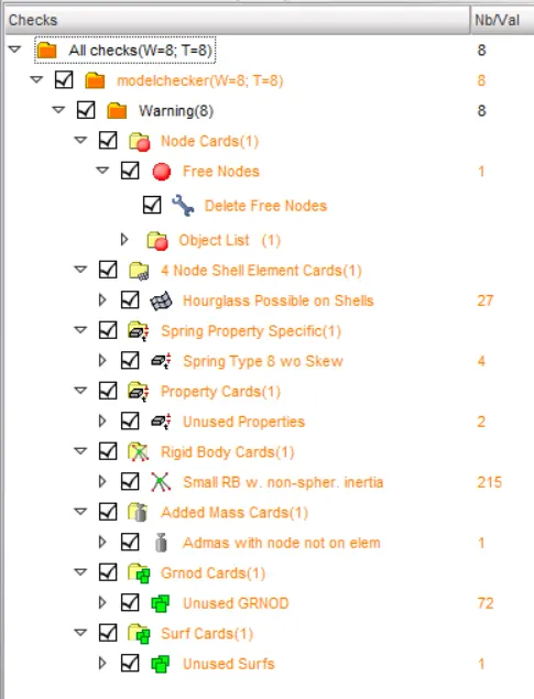
A model checker is used to see the errors in the model as shown below. A few spherical and translational free joints are found and rectified. The unwanted free nodes are also removed.
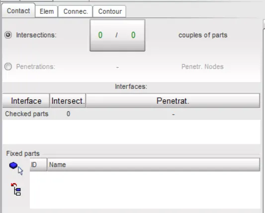
Penetration is checked by using the Quality->Check intersection of tree nodes. No penetrations are present in the model.
4. Correction of Rigid body:
There were some rigid bodeies which were not required for simulation. Those have been removed in the above model checker.
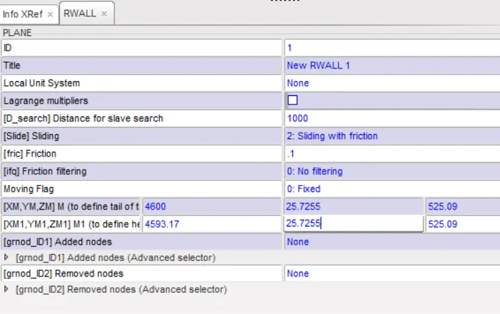
5. Create rigid wall with friction 0.1.
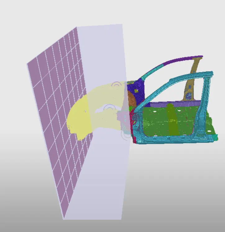
6. Compare the model weight with the full scale 300k nodes model and use added masses to reach target weight 700kg while getting CG about the required range.
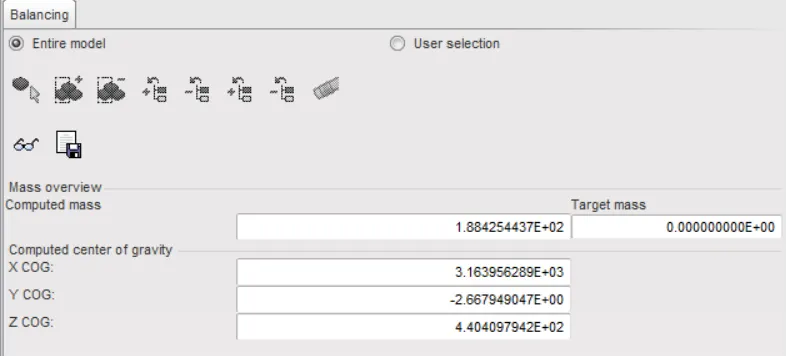
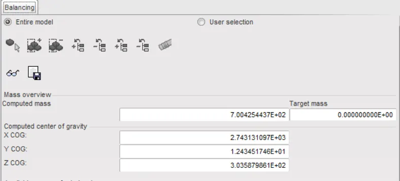
Extra mass is added near the passenger side of 150 kg, Back of the vehicle of about 300 kg and near the engine part of about 60 kg.
The overall mass increased to 700 kg and centre of gravity of the car has shifted towards the centre of axis connecting the drivers side. This is a suitable COG as this helps in better real life crash analysis.
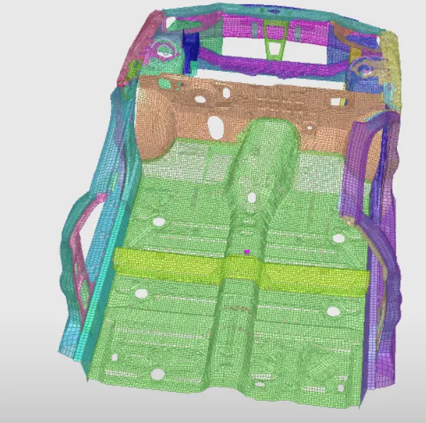
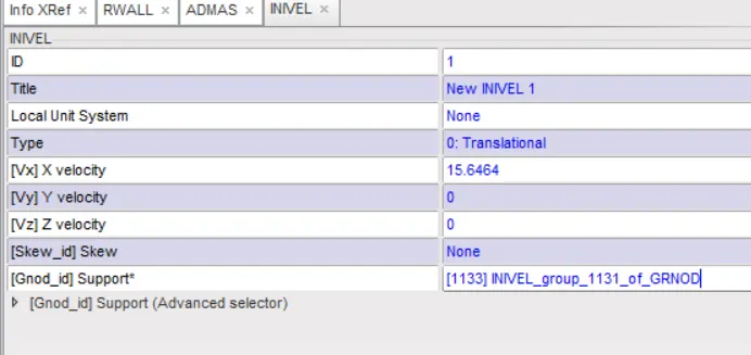
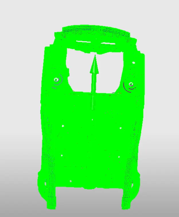
7. Initial velocity 35 mph.
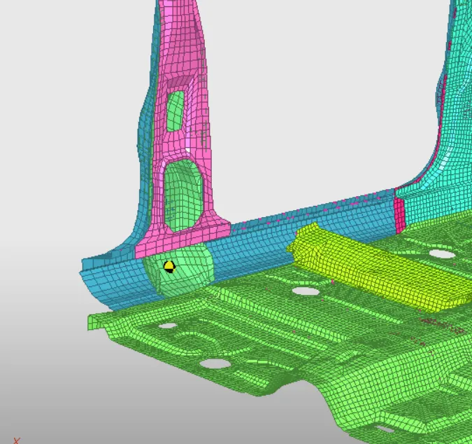
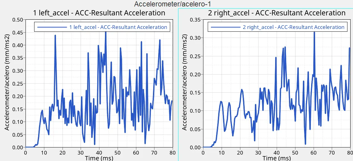
Accelerometers are attached to base of B pillar to calculate acceleration on vehicle due to crash.
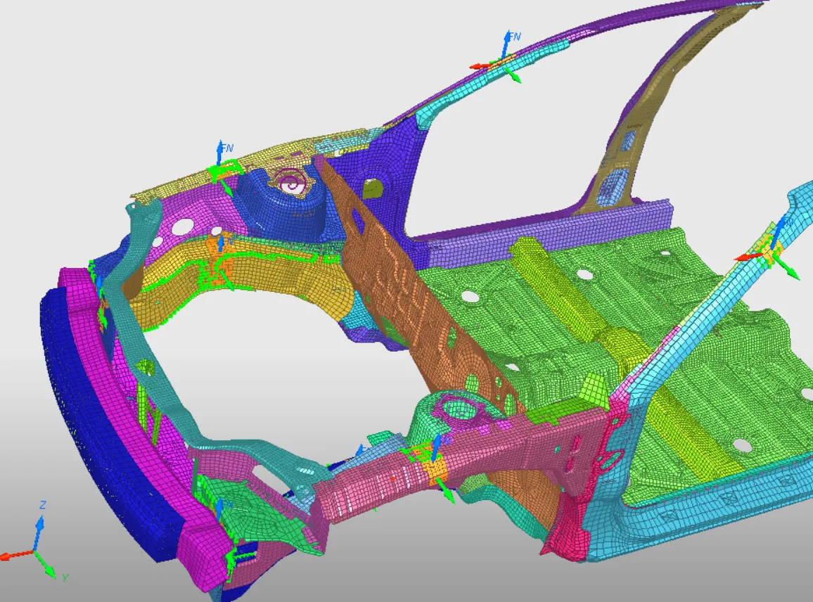
Sections are made at following areas such as shotgun, rail, fender and A pillar to calculate the resultant normal forces coming on to these sections
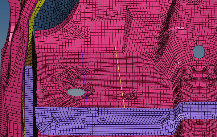
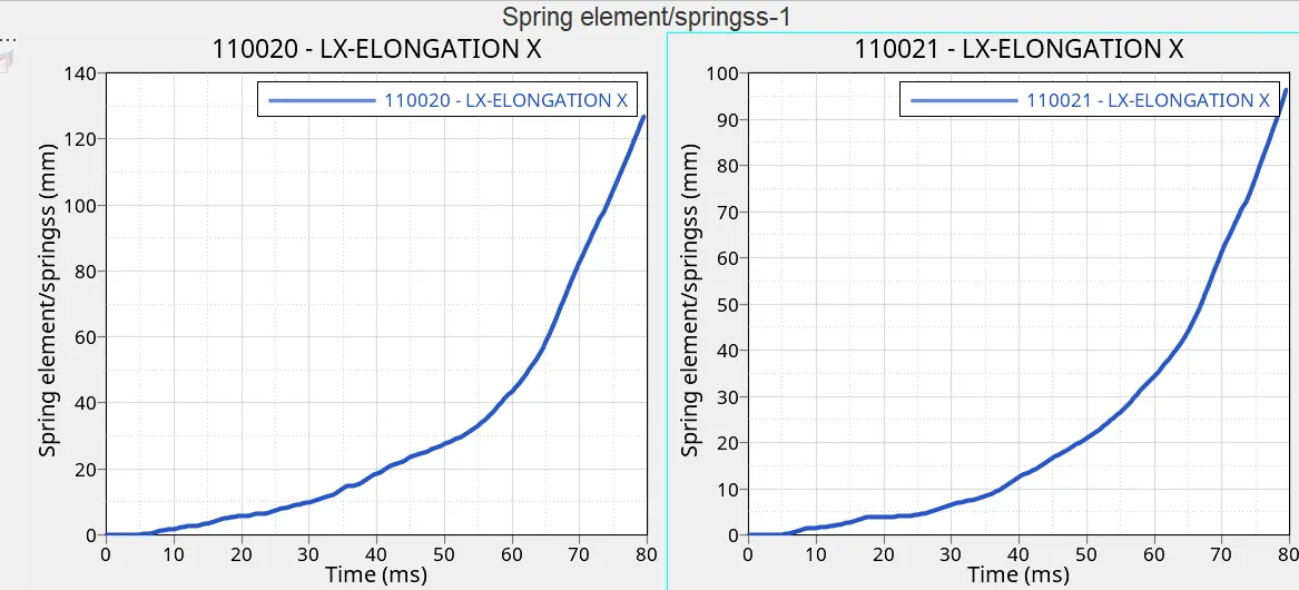
Spring elements are created as shown below to calculate the intrusion coming on to the brake and acceleration pedals due to crash.
8. Use model checker to ensure good quality.
After setting all the parameter, checked the mode wheather all the function and parameters assigned properly or not. To check it clicked on the Quality option--->Model checker-->Run
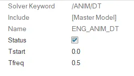
9. Time-step 0.5 to 0.1 ms:-
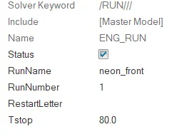
The run time is set to 80ms as shown below
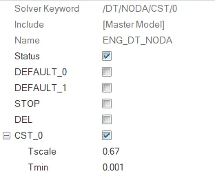
The nodal time steps are set to 0.1ms with a scale factor of 0.67 so that if the time step falls below 0.1/0.67= 0.15ms extra mass will be added to increase time step.
Animation files is set to be created every 0.5ms.
10. Run:-
The simulation is run in Radioss using the -both -nt 4 command for 80ms.
Results:
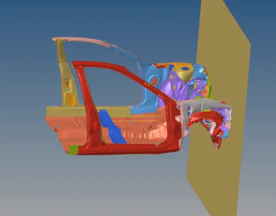
Error

Mass error = 0.4041e-1
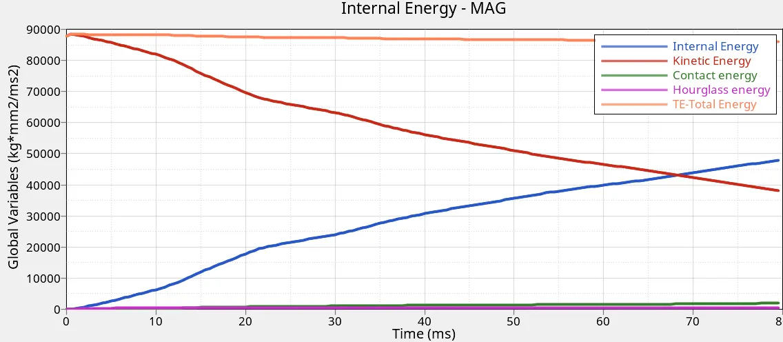
Energy error = -1.4 % which is in acceptable range.
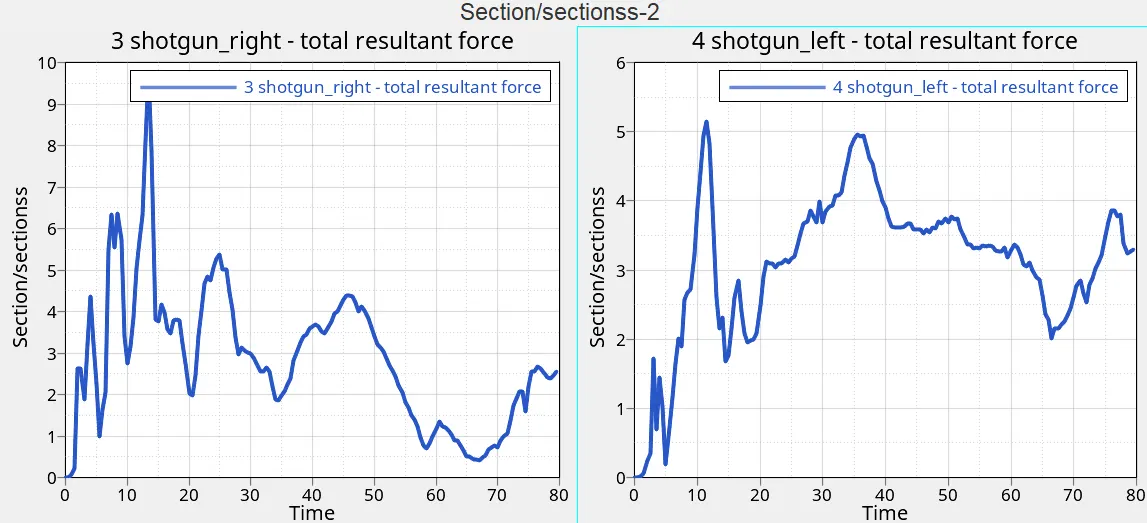
Shotgun sectional forces
Shotgun takes the force directly from the bumper.
As seen below the forces are high on right side shotgun. This might be due to the way the rigid wall is inclined or due to the mass distribution defined in the model. The mass might be more towards right of the model due to which more impact forces are imparted on that side.
Max Force right shotgun = 9.769 kN at 13.5 ms
Max Force left shotgun = 5.153 kN at 11.5 ms
Rail sectional force
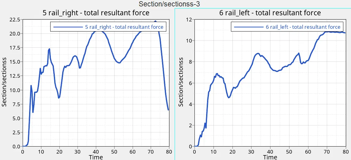
Rails transmits the load towards the back of the car. As seen in graph below the forces are transmitted in somewhat uniformly along both the rails. Most of the impact force will be taken by the rails for passenger protection.
Maximum right rail sectional force = 22.2312 kN at 72.5 ms
Maximum left rail sectional force = 10.847 kN at 71 ms
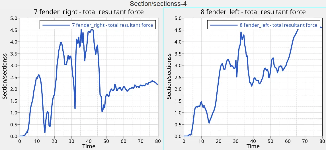
Fender sectional force
It is the side rails present in a car. Mostly they take forces during side crashes. It can be seen that the load transmission is less than the rails. The transmission is mostly jerky as seen below.
Maximum right fender sectional force = 4.58 kN at 41.5 ms
Maximum left fender sectional force = 4.69 kN at 73 ms
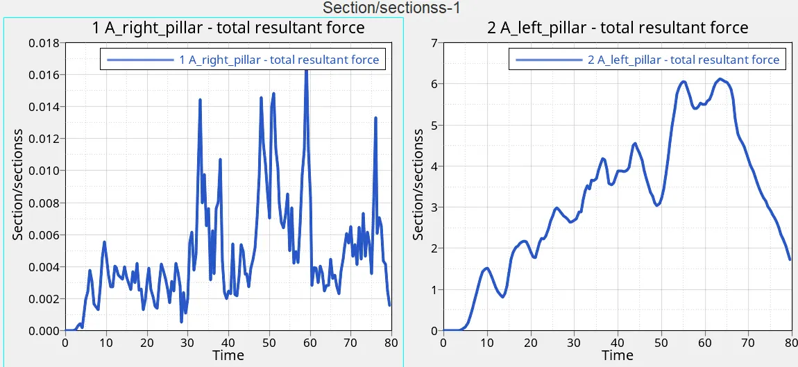
A pillar sectional force
This is the part near the door areas. Most of the force will have discipated by the time it reaches this point.
Maximum right sectional force = 0.017 kN at 59 ms
Maximum left sectional force = 6.23 kN at 64.5 ms
Intrusion
It is calculated to find the amount by which the brake and acceleration pedal regions are moving in due to frontal crash.
Brake pedal = 124 mm
Acceleration pedal = 94.3 mm
Accelerometer
It is seen that the crash is very jerky as understood from below graphs.
right maximum = 0.31 mm/ms2 at 44 ms
left maximum = 0.45 mm/ms2 at 60.5 ms
Energy
The kinetic energy is converted into internal energy due to crushing. During crushing the elements absorb the energy and store them in the form of internal energy.
Conclusion:
1. The simulation is not accurate to real life as the engine and rest of the parts are missing.
2. Forces are calculated at shotgun, rail, fender and A pillar. The maximum forces are recorded in the rail region and the minimum at fender regions.
3. Accelerometer readings provide the amount of jerkiness in the crash. The jerks are more towards the right side.
4. The intrusion of pedal seems to be in a safe limit.