Assignment 6
AIM:
- To list down different Turbo Chargers and locate examples from GT-Power
- Explore the tutorial no. 6 and 7
- To plot operating points on the compressor and turbine maps
- To find in which application Variable Geometric Turbine is beneficial
- To Explore example- Diesel VGT EGR and understand the modeling part
METHODOLOGY:
Different types of Turbochargers and its examples available in GT Power
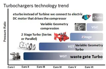
- Waste Gate Turbocharger
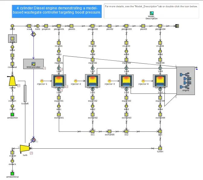
Fixed Geometry Turbine – Energy is fixed or energy from exhaust goes into the turbine directly increasing the chances of mechanical failure. In order to avoid such failure Waste Gate Turbocharger was developed wherein a pneumatic PID controller is connected with the compressor outlet to sense the compressor output pressure and then adjust the pneumatic pumps stiffness to the desired pressure and the remaining exhaust gas energy is bypassed.
Application: High speed and torque applications.
Example case for Waste Gate Controller from GT-Power:
Figure 1:
- Variable Geometry Turbine & Variable Geometry Compressor
- In case of Variable Geometry Turbocharger the ability to bypass the excess exhaust gas is achieved through a ring of aerodynamically shaped vanes in the housing of the turbine inlet which are also known as guiding vanes. By rotating the vanes we can vary the gas swirl angle and thus the cross sectional area or wedge. The area - to - radius (A/F) ratio is altered by the vanes to match the engine RPM say for narrow A/F for low RPM and vice versa.
- Application: High speed and torque applications.
- Example case for Variable Geometry Turbine from GT-Power:
Figure 2:
- Two-stage Turbocharger
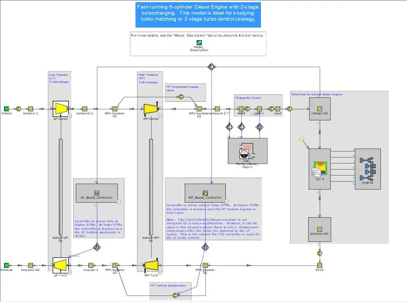
For engines with more number of cylinders say V6 or V8 engines, the two-stage turbocharger can be used by allotting discrete turbocharger for each cylinder or bank. Twin Sequential Turbocharging is used for applications where smaller turbo is used at low RPM and larger turbo for higher RPM.
Application: used in places where wide operating RPM range and high power requirement is needed
- Example case for Two stage Turbocharger from GT-Power:
Figure 3:
- e-Turbo
Turbo lag which is a common setback for normal turbocharger is overcome by Electric Turbocharger.Turbo Lag ie., Turbo charger works based on the exhaust KE that runs the turbine which in turn runs the compressor and required pressure is produced. This takes time and that is why in city diesel engine with turbo is not that effective.
It eliminates turbo lag at a lower engine speed by adding an electric motor connected with compressor during the lower revolutions until the power from the exhaust volume is high enough to work the turbocharger efficiently.
Application: Effective work at low rpm is required.
Disadvantages: Cost and complexity.
- Explore the tutorial no. 6 and 7
- To plot operating points on the compressor and turbine maps
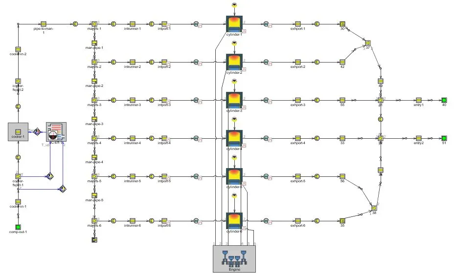
Tutorial 6: 6 cylinder Diesel Turbocharger
The tutorial consists of 6 cylinders with Turbo Charger having 2 inlets to the turbo in the form of two end environments and compressor outlet at the bottom in the form of end environment. Twin Turbine inlets are generally used with more than 3 cylinders. Since here we have 6 cylinders where 3 outlets of cylinders share the turbine inlet. There is no physical shaft connecting the turbine and compressor thus the oultet pressure input is directly given. The inputs for the turbine and compressor are absolute pressure, temperature and composition of air.
Figure :
Tutorial 7:TurboCharger
The tutorial consists of 6 cylinder diesel engine with the two inlets to the turbocharger. The exhaust gas collected from 6 cylinders is splitted into 2 inlets to turbocharger. This model is same as Tutorial 6 model the only difference is the implementation of actual turbocharger setup. It consist of a turbine connected with compressor impeller by a rotating shaft.
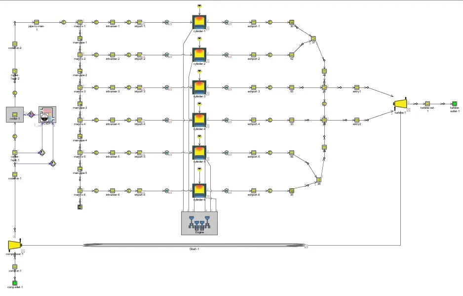
It is evident that here a turbine map and compressor map (contour plot of Pressure ratio v/s Mass flow rate) is used for inputs of turbine and compressor. The turbine and compressor map data consists of parameters like Mass flow rate, Rotational speed, Pressure Ratio and efficiency.
To plot operating points on the compressor and turbine maps
The Compressor maps and the turbine maps are provided by the supplier or Manufacturer of the part in a standard SAE format having an extension of .cmp for compressor and .trp for turbine. GT power also has an alternative option to directly give the attributes of the map like speed, mass flow rate, pressure ratio and efficiency.
We use the compressor Map and turbine to understand the boundaries of compressor or turbine. Depending on our requirement whether the compressor will fit or not ie., the operating points are lying outside or inside the boundary. From map we find Pressure ratio for the given mass flow parameter.
Dark blue line is the speed line indicate the speed in RPM, and the thin vertical rail lines indicate the efficiency of the compressor. At Red line the efficiency are maximum so we need to keep the operating points on it or at heart ( Location in middle of map where highest efficiency of the compressor and efficiency decreases as we move outwards).
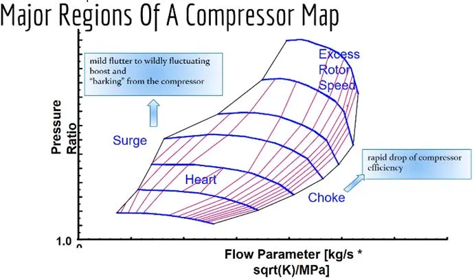
The x-axis represents the Mass flow rate and Y-axis represents the Pressure Ratio.
Zones in Map:
Choke zone – compressor efficiency comes down very drastically
Surge zone – noise zone
Excess rotor speed – Never cross the limiting speed values else will lead to mechanical failure - Avoid operating points in this region
Plot the compressor and turbine map with 6 cylinders turbocharged diesel engine
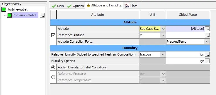
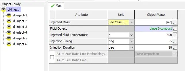
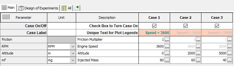
3 cases were studied by changing altitude and the amount of fuel to achieve maximum compressor efficiency
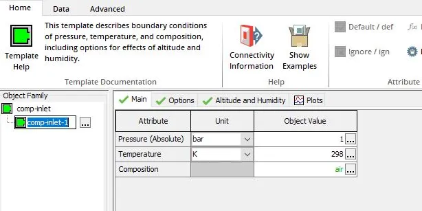
Modelling Parameters
Cases:
RESULTS AND DISCUSSION
Plots
Compressor Map
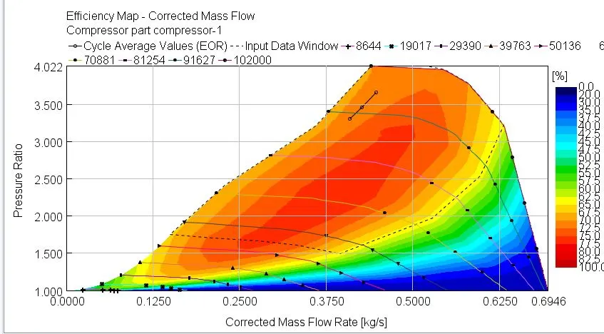
Inference: It is envisaged from the efficiency Map with the corrected mass flow rate for the compressor that :
| CASE | Pressure ratio | mass flow rate (kg/s) |
| 1 | 3.6608 | 0.4475 |
| 2 | 3.4632 | 0.426 |
| 3 | 3.3088 | 0.409 |
The efficiency of the compressor is around 70-72%.
Turbine Map
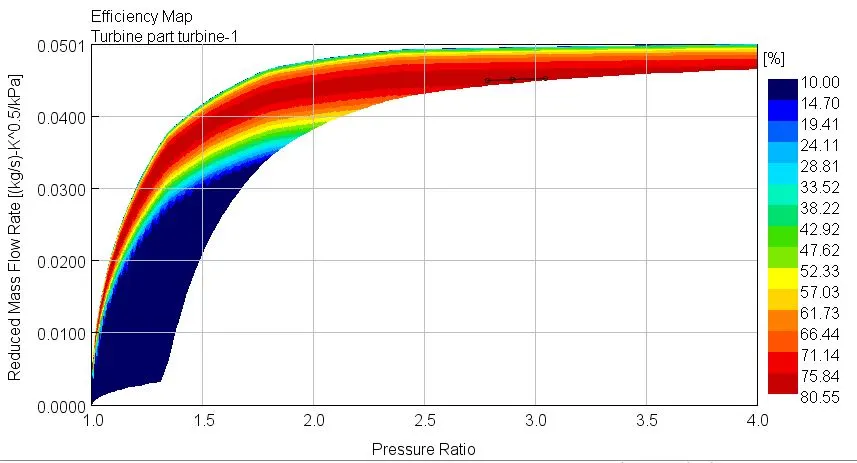
Inference: It is envisaged from the efficiency Map with the corrected mass flow rate for the compressor that :
| CASE | Pressure ratio | mass flow rate (kg/s) |
| 1 | 3.0478 | 0.0452 |
| 2 | 2.8997 | 0.0451 |
| 3 | 2.787 | 0.045 |
The efficiency of the turbine is around 80%.
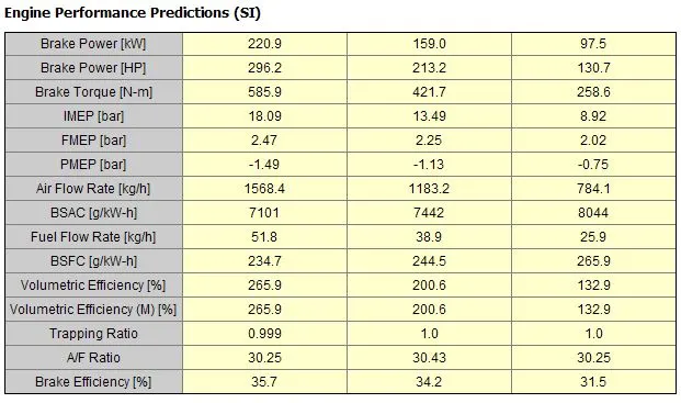
Inference: With increase in altitude, a decreasing trend in Brake Power, Torque and increase in BSFC Consumption is seen.
Applications where Variable Geometric Turbine is beneficial
Variable Geometric Turbine requires 'electronic controller' to achieve different speed and load conditions. It is beneficial to be used in high end vehicles which requires wide range of operating RPM and high torque. It is also used in on and off highway, marine and rail applications.
Explore example- Diesel VGT EGR and understand the modeling part
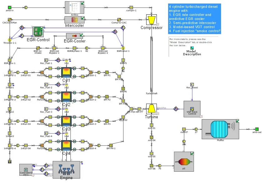
Modelling:
Inference: At environmental pressure Ambient air is been sucked into the Airbox. Variable geometry turbocharger is used to force more air into cylinder. The ambient air from the airbox is compressed increasing its pressure, temperature and density. Compressed air is then passed through an intercooler to lower down the air temperature and increase its density which increases the amount of air to be supplied to the intake manifold and volumetric efficiency of the engine. The intercooler used here is an air to air intercooler. An EGR system is integrated with the model which also adds up the air coming from the intercooler with exhaust gas and then charge goes to the intake manifold. Positive pressure difference is maintained between the exhaust manifold and the intake manifold by an orifice connection. Once the exhaust gas is mixed with the mainstream it enters the manifold of 4 cylinders having 2 intake and 2 exhaust valves.The firing order is 1 -3 - 4 - 2 and a controller is used for Diesel Injection to maintain the targeted BMEP by controlling the injected fuel quantity. Then a single scroll turbine to rotate the compressor through shaft. Compressor and turbine map files are given as input. Finally turbine expansion, the exhaust gas passes through after-treatment devices.