Assignment 6
Aim: This project aims to successfully troubleshoot and setup a FE model for the front assembly crash simulation of Dodge Neon (100K Elements).
Objective:
- Check unit system and either follow [Mg mm s] or [Kg mm ms].
- Create appropriate interfaces with a friction coefficient of 0.2 along with recommended parameters.
- Check for penetrations and intersection.
- Correct rigid bodies if required.
- Create a rigid wall with a friction coefficient of 0.1.
- Compare the model weight with the full-scale 300k nodes model and use added masses to reach the target weight of 700kg while having the COG in the appropriate location.
- Use an initial velocity of 35 mph.
- Use model checker to ensure good quality.
- Recommeded Time-step :0.5 to 0.1 microseconds.
- Run Time: 80 ms.
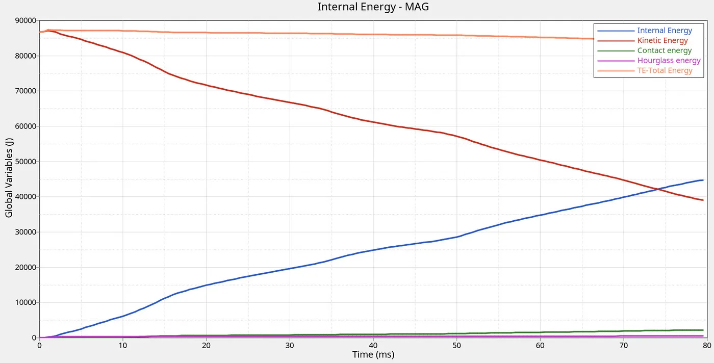
- Plot energies and notice any difference.
- Explain your errors and how to rectify?
- Submit your simulation files including time and h3d files.
Output requests:
- Sectional force in the rails at the location of indicated node 174247.
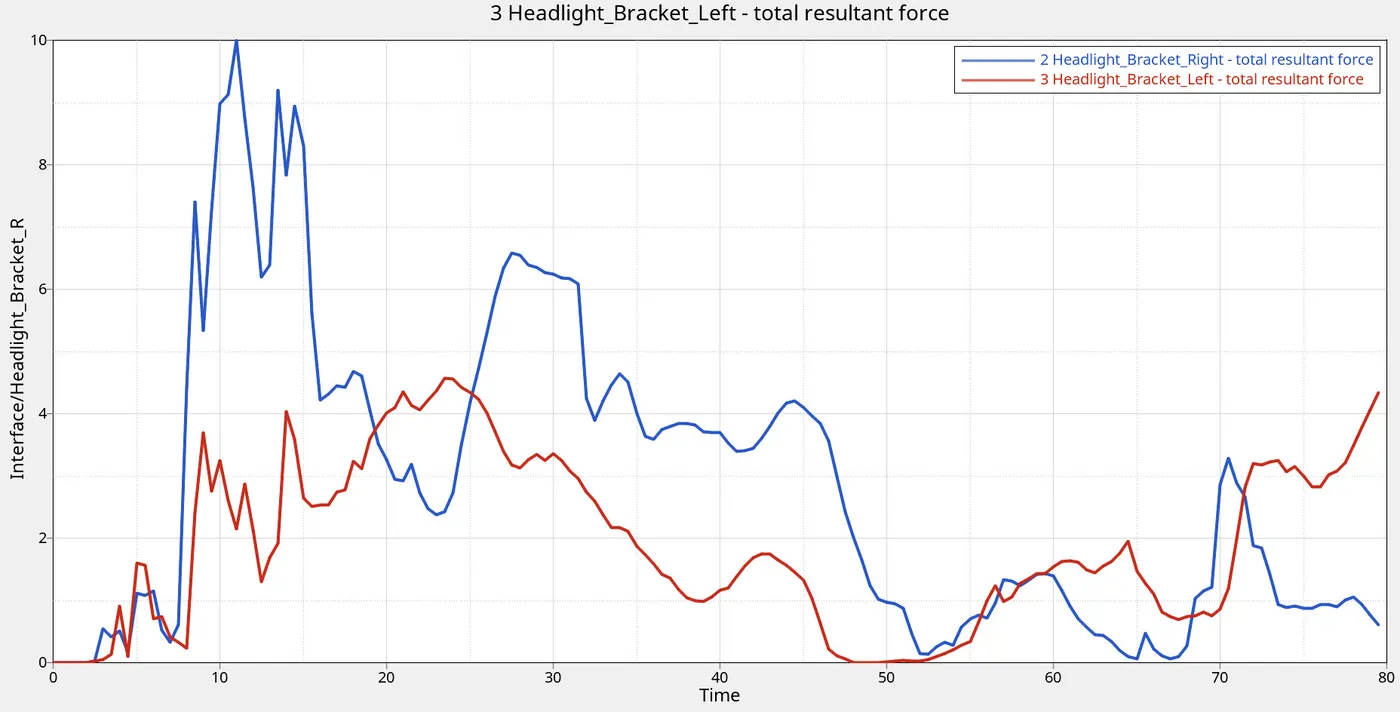
- The axial force received on the rails from the bumper.
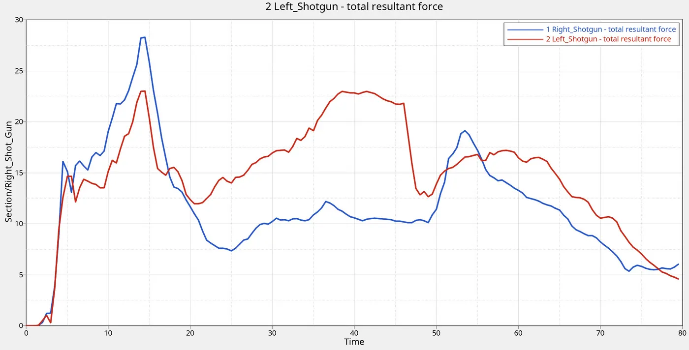
- Shotgun cross-sectional forces.
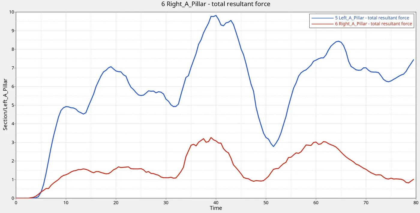
- A-pillar cross-sectional forces.
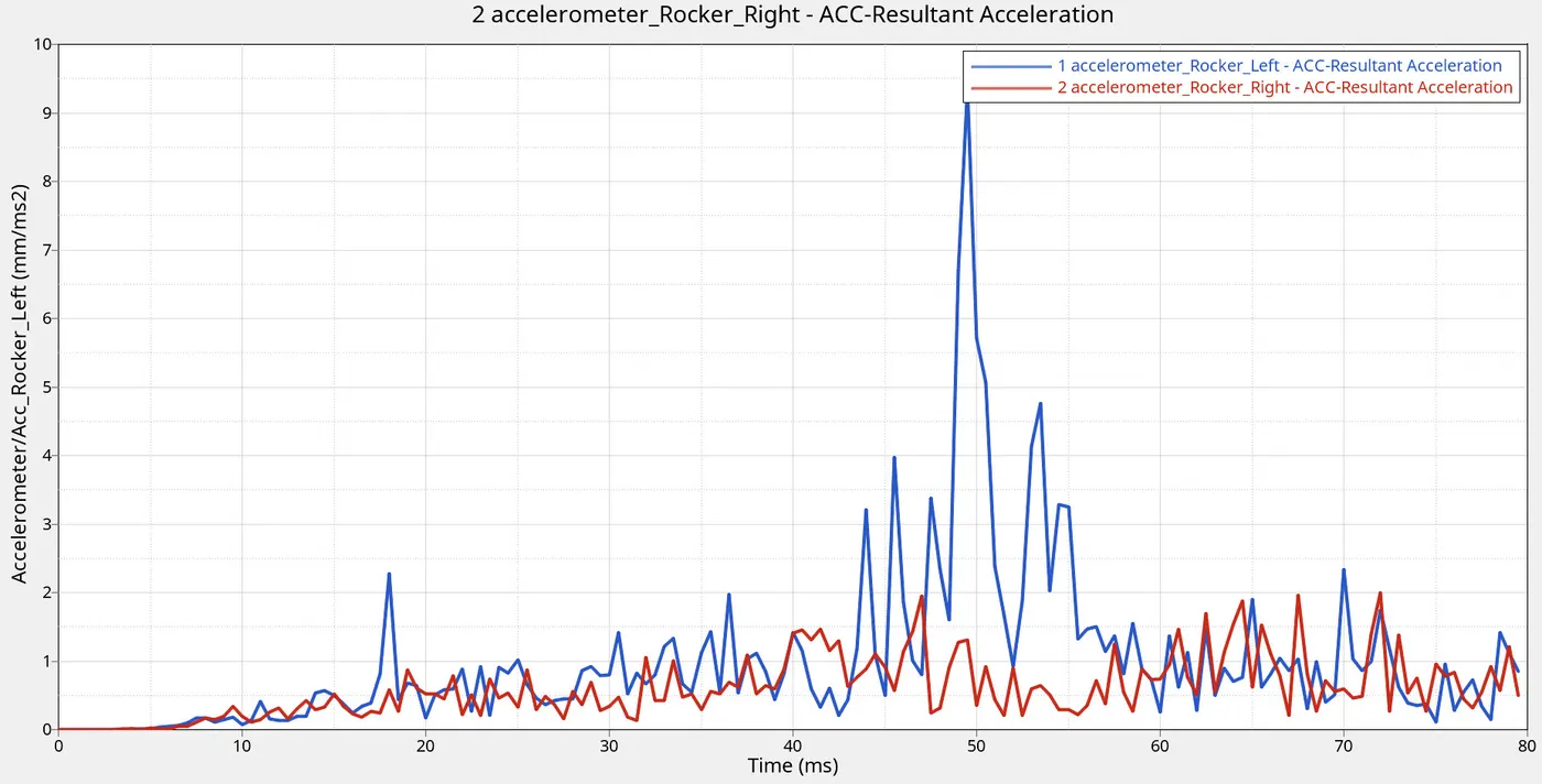
- Acceleration curve received on the accelerometer at base of B pillar (on B pillar rocker).
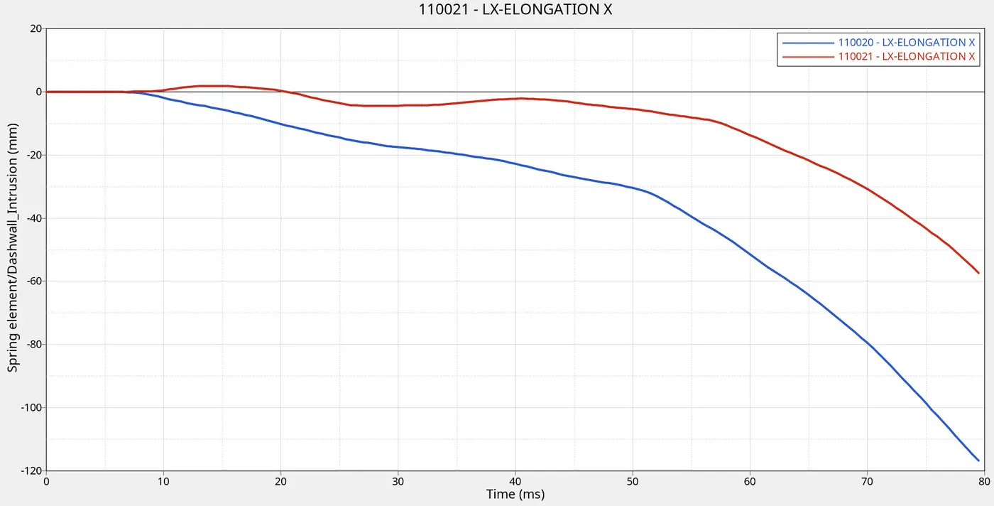
- Intrusions on the dash wall (ref node 66695,66244).
Case Setup and Execution:
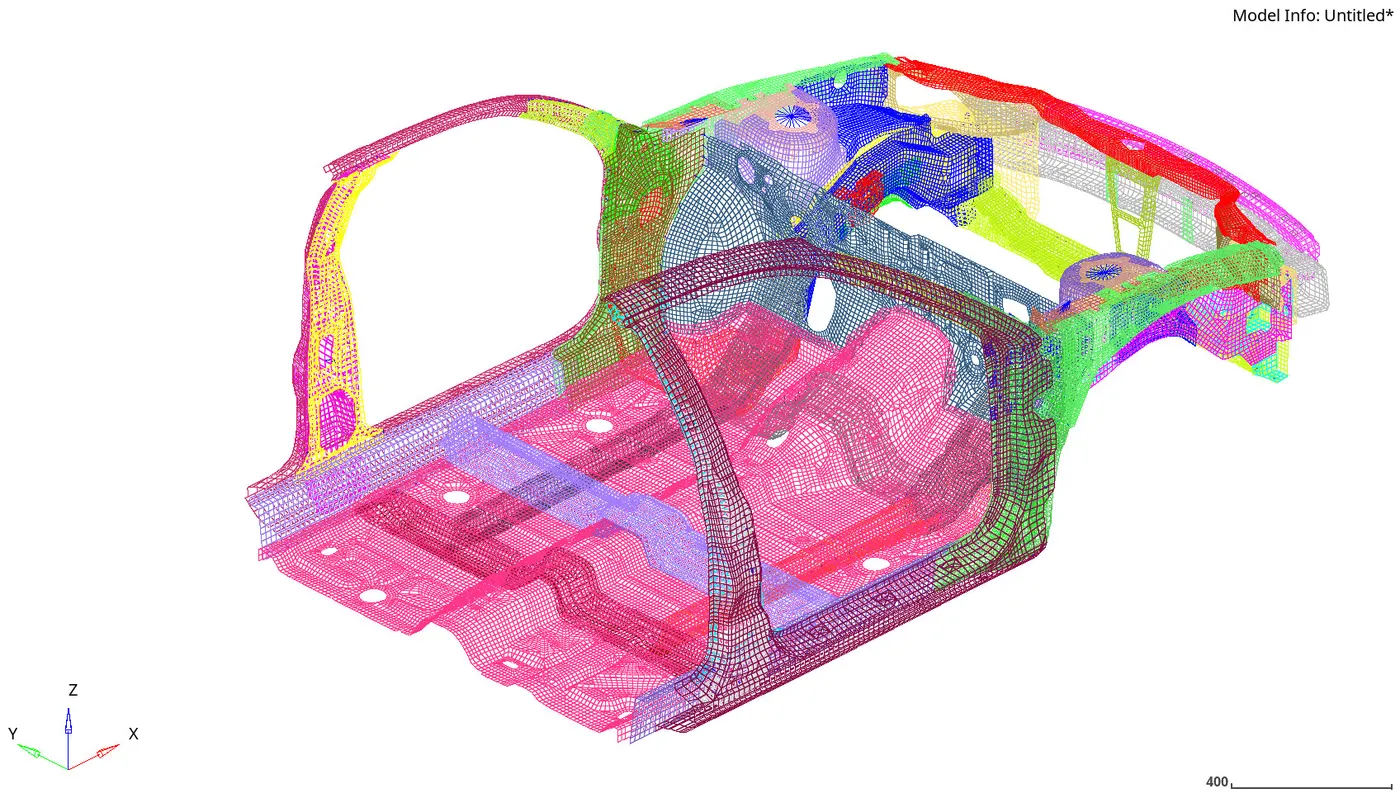
Figure-1 illustrates the front assembly of Dodge Neon under review.
 |
Unit System
For this project, the unit system mm-kg-ms is selected.
Interface
The existing interfaces are deleted and a global interface using a Type 7 is defined using the parameres described in Table-1.
| Igap | 3 |
| Gapmin | 0.5 |
| Inacti | 6 |
| Istf | 4 |
| Stmin | 1000 |
| Idel | 2 |
| Iform | 2 |
| nu | 0.2 |
Penetration Check
The assembly is checked for any penetrations using the Penetration Checker tool. The entity type group was selected with a thickness multiplier of 1. No penetrations are found.
Free Bodies
The connectivity of each part is checked for any free bodies using Check Connectivity tool. Two free bodies (Translational Joints) are found are deleted.
Rigid Wall
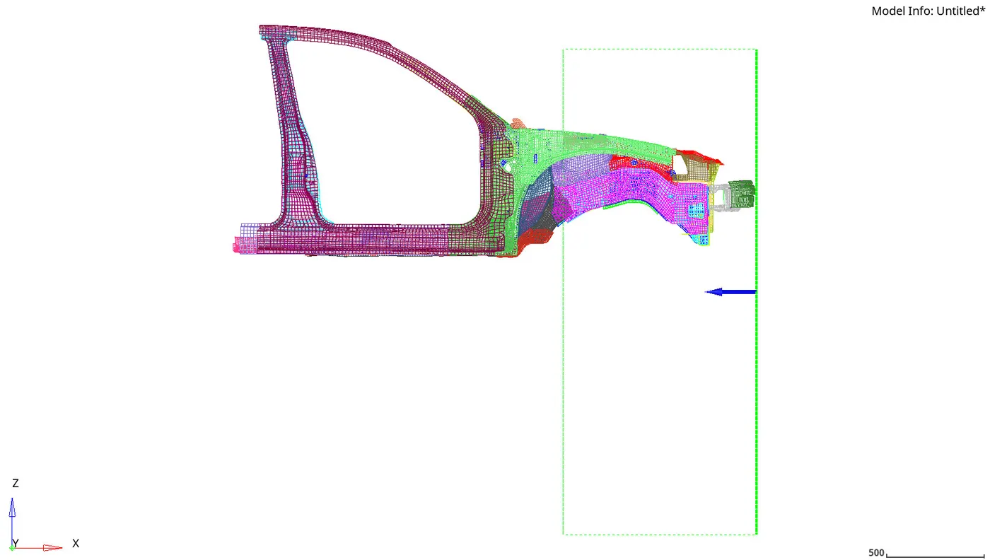
A rigid wall is generated using parameters defined in the full-scale model as a reference with a coefficient of friction of 0.1. Figure-2 illustrates the front assembly with a rigid wall definition.
 |
COG and Mass
Target mass of the model must be 700 Kg and the current mass of the model was 188 Kg. Thus 512 Kg must be added to the model such that the x and y coordinates of the current model are close of the COG os the full model.
The new COG os the model was reported as x_cog = 3151.9 and y_cog = 6.01. Compared to the full-scale model the COG shows 0.38% and 4.16% relative error in the x_cog and y_cog which is within the acceptable limit of deviation.
Initial Velocity
An initial velocity of 35 mph (15.6464 mm/ms) was defined.
Model Checker
The model checker was run to ensure the model was free of any errors.
Model Setup for Data Extraction
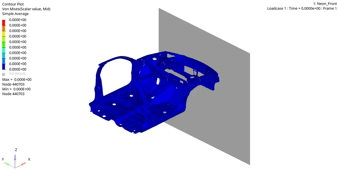
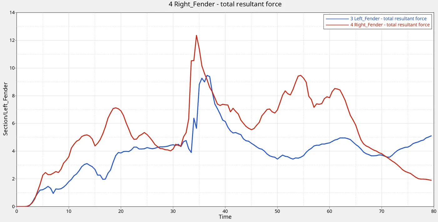
Cross-sections are generated at the left and right shotgun, fender, and A_Pillars. The axial force transferred on the rails from the bumper is calculated by measuring the contact force between the bumper and the left and right headlight bracket. Accelerometers are defined at the base of the left and right B-Pillars. Intrusions on the dash wall and the brake pedal are measured using the linear displacement of the 2 noded spring of negligible mass and stiffness. The model is run for 80 ms. A maximum energy error of -1.9% and a mass error of 3.89% is recorded which fell within the acceptable limits of deviation. The results describing the von-mises countors, the variation of global energies, the cross-sectional forces and the dash wall intrusion is described in the next section.
Results
Animation
 |
Global Energies
 |
Shotgun Cross-Section Forces
 |
Fender Cross-Section Forces
 |
A-Pillar Cross-Section Forces
 |
Acceleration at Base of B-Pillar
 |
Axial Force at Rails
 |
Dashwall and Brake Pedal Intrusion
 |
Conclusion
The frontal crash performance of front assembly has been studied successfully. The simulation files requested are attached to this assignment as a compressed zip file.