Assignment 6
1. Single turbo
The simplest, and still most common, type of turbo is the single-turbocharger set-up. Because of its relative simplicity (compared to the other options on this list), it is the cheapest, but arguably not the best, turbo option available. A single turbocharger can’t be effective across the whole rev range. Generally speaking, you have to choose either a smaller turbo that kicks in lower down on the rev counter and offers good low-down torque, or a larger one that will provide more top-end power. In either case, the boost range will be fairly narrow, and lag will be an issue.
2. Sequential turbos
Having to choose between a small low-end turbo or a big high-end one presents a rather intuitive solution: fit two, one small and one large. That way you have a small turbo that kicks in early and provides good torque, and a bigger one that offers top-end grunt, resulting in a wide and flat torque curve. On the downside, quite obviously, you’re left with an engine set-up that is expensive, heavy and complex.
3. Twin-scroll turbo
A turbo is powered by exhaust gases that are redirected to spin turbine blades and force air into the engine. Now, an engine’s cylinders fire in sequence, meaning that exhaust gases enter the turbo in pulses. As you can probably imagine, these pulses can easily overlap and interfere with one another when powering the turbo, and a twin-scroll turbocharger solves this issue by using a divided-inlet turbine housing and a specific exhaust manifold that pairs the right cylinders to each scroll. In a four-cylinder vehicle, you can then have the first and fourth cylinders powering one scroll, and two and three powering another. This means that there’s less pulse overlap and less lag.
4. VGT turbo
A variable geometry turbo (VGT) is an expensive and complex power solution that’s especially prevalent in diesel engines. A VGT has a ring of aerodynamically-shaped vanes in the turbine housing that can alter their area-to-radius ratio to match the revolutions of the engine. At low revs, area-to-radius ratio creates more pressure and velocity to spool up the turbo more effectively. At higher revolutions, the ratio increases to let in more air. The result is a wider boost range and less lag.
5. Variable twin-scroll turbo
A variable twin-scroll turbo combines a VGT with a twin-scroll setup, so at low revolutions, one of the scrolls is closed completely, forcing all the air into the other. This results in good turbo response and low-end power. As you speed up, a valve opens to allow air into the other scroll (this is a completely variable process, meaning the valve opens in small increments), you get good high-end performance. You get the sort of performance from a single turbo that you’d normally only be able to get from a twin-turbo set-up.
6. Electric turbo
A very recent development is the introduction of turbos with electric compressors. An example is BorgWarner’s eBooster, which is an electrically powered compressor. The compressor provides instant boost to the engine, until the turbocharger has spooled up enough. A similar version of this can be found in Audi’s SQ7. With instant boost, lag becomes a thing of the past, but again, the system is expensive and complex. A compressor needs a motor, which in turn needs to be powered, so this is not a simple system to implement.
There are some standard turbocharger examples in GT-SUITE ,that are as follows:
wASTEGATE TURBOCHARGER
VARIABLE GEOMETRY TURBOCHARGER
TWINSCROLL TURBOCHARGER
And there were some superchargers for passsenger type vehicle engine
Example simulation of wastegate turbocharger
Nowadays, vehicles with turbocharged engines feature the wastegate turbocharger. This technology helps to deliver optimum engine performance during peak operating conditions. In addition, the wastegate valve prevents the turbocharger from over-running. Particularly, it also avoids the engine from over-boost and prevents any mechanical failure.
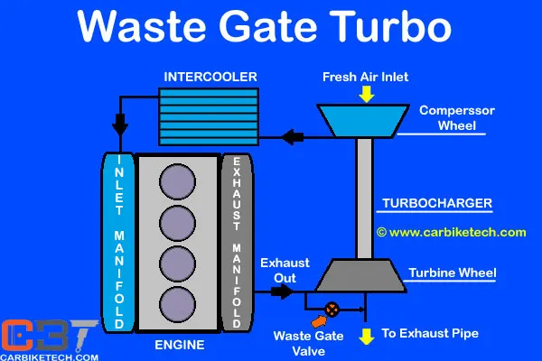
This feature in the turbocharger consists of a bypass valve. It circumvents some part of the exhaust gas going to the turbine and releases them into the outlet. Furthermore, the waste-gate turbocharger has a bypass valve built into the turbine housing. It diverts some of the exhaust gases away from the turbine wheel through this valve.
COMPRESSOR AND TURBINE SETUP:
CASE SETUP:
The engine had been simulated for two rpm's 5000&4000 at full open of throttle position.
RESULT FOR WASTEGATE TURBOCHARGER:
the compressor and the turbine were operated at the optimum area in the maps for both rpm's.
Example simulation for variable geometry turbine:
Variable Turbine Geometry technology is the next generation in turbocharger technology where the turbo uses variable vanes to control exhaust flow against the turbine blades. See, the problem with the turbocharger that we’ve all come to know and love is that big turbos do not work well at slow engine speeds, while small turbos are fast to spool but run out of steam pretty quick. So how do VTG turbos solve this problem?
A Variable Turbine Geometry turbocharger is also known as a variable geometry turbocharger (VGT), or a Variable Nozzle Turbine (VNT). A turbocharger equipped with Variable Turbine Geometry has little movable vanes which can direct exhaust flow onto the turbine blades. The vane angles are adjusted via an actuator. The angle of the vanes vary throughout the engine RPM range to optimize turbine behaviour.
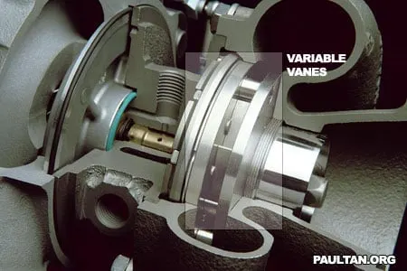
In the 3D illustration above, you can see the vanes in a angle which is almost closed. I have highlighted the variable vanes so you know which is which. This position is optimized for low engine RPM speeds, pre-boost.
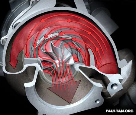
In this cut-through diagram, you can see the direction of exhaust flow when the variable vanes are in an almost closed angle. The narrow passage of which the exhaust gas has to flow through accelerates the exhaust gas towards the turbine blades, making them spin faster. The angle of the vanes also directs the gas to hit the blades at the proper angle.
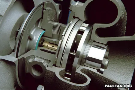
Above are how the VGT vanes look like when they are open. I’ve not highlighted where the vanes are in this image since you already know where they are, as to not spoil the mechanical beauty that it is :P
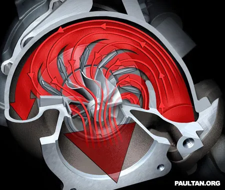
This cut-through diagram shows the exhaust gas flow when the variable turbine vanes are fully open. The high exhaust flow at high engine speeds are fully directed onto the turbine blades by the variable vanes.
Variable Turbine Geometry has been used extensively in turbodiesel engines since the 1990s, but it has never been on a production petrol turbocharged car before until the new Type 997 Porsche 911 Turbo. This is because petrol engine exhaust gases are alot hotter than diesel engine exhaust gas, so generally the material used to make VTG turbos could not stand this heat. The 997 911 Turbo uses a BorgWarner VTG turbocharger which uses special materials derived from aerospace technology, hence solving the temperature problem.
BENIFICIAL OF VGT:
Compared with fixed geometry turbochargers, variable geometry turbochargers are designed to:
- increase intake air boost pressure at low engine speed
- improve the response time of the turbocharger during transient engine operation phases
- increase the availability of the maximum engine torque
- prevent over-boosting at high engine speed
- reduce exhaust gas emissions and improve fuel economy,VGT is benificial in passenger cars.
RESULT FOR VGT :
example- Diesel VGT EGR
In this example there was four cylinder internal combustion engine which was operated with diesel as fuel,a variable geometry turbocharger,a exhaust gas reciculation system were present and a catalytic convetor system also present there.initailly the air from the ambient and the exhaust gas from the EGR were send to the compressor due to the turbine rotation the comperssor compresses the inlet air for combustion ,after compressor the inlet air send to the intercooler to cool the comperssed air after intercooler the air send to the throttle valve according to the opening level of throttle valve the air sends to the cylinder block.
At the time of suction stroke the air was sucked into the cylinder through inlet valve,at the end of compresssion stroke the fuel was introduced to start the combustion process,after combustion the power will produce and at the end of exhaust stroke the exhaust gas send to the exhaust manifold from ex-manifold the ex-gas send to turbine and EGR set up to continue the processes to produce continious power.