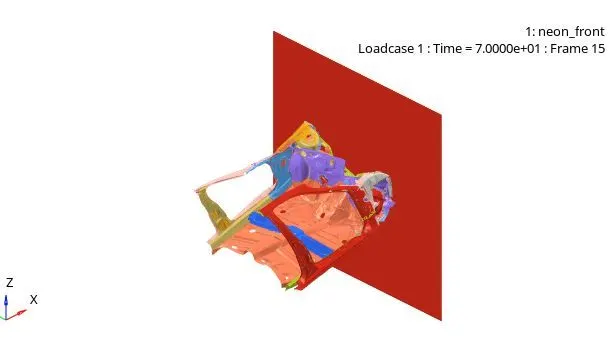
Assignment 6
AIM:
To set up a case for Frontal crash-biw (Body in white) of neon car and successfully run the simulation for the given condition also note the error and energy changes.
Solution:
-First we need to check for the unit system,here we have made use of [Kg mm ms].And we can see or check this by downloading the file and vewing it in notepad format neon_front_0000.rad file.
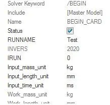
-Here now we have to create an appropriate interface,friction 0.2 and recommended parameters.Now we have to delete the available interface in original model and finlay create a new type 7 interface.
-Recommended properties is as follows:
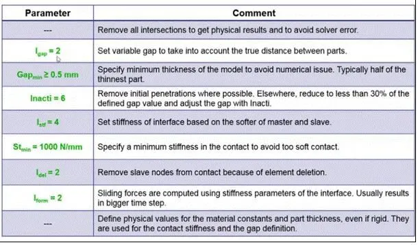
-To create Type 7 in hypermesh right-click>create>contact>Type 7,give appropriate value and friction as 0.2.
-Initially we have to import the model into hypercrash by using the option File>Import>Radioss>select the file and click on OK.
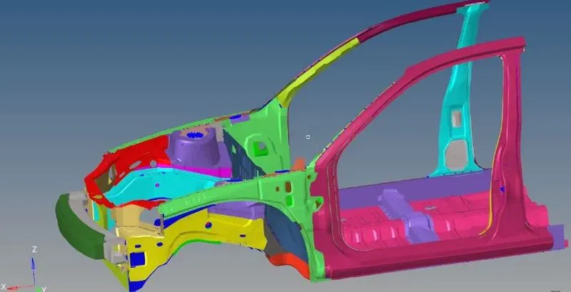
-To create interface in hypercrash:
-To create Type 7 in hypercrash select in load case from top up menu>contact interface>create new>multi (use Type 7) apply appropriate properties and friction as 0.2
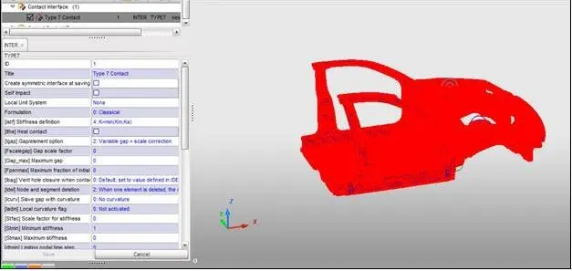
-To make sure of no penetration or intersection:
-Before running the simulation we should make sure that there is no intersection and penetration between two parts of body.Now to perform those operations we need to load case in upper menu tab>contact interface >select contact type 7>click on penetration for selected objects.
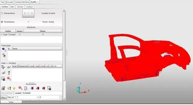
-As observed on our case we donot have any penetraion or intersections so our model can be runned for analysis.But in case if there is any penetration or intersection issue we can fix it by using auto fix tool or by using manual method.And also as per observation we did not find any rigid body issue.
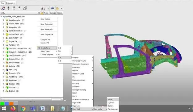
-To create a rigid wall with friction 0.1:
-To create rigir wall in hypercrash,Right click>create new>M-R>Rigid wall >plane.Set the parameter as per hypemesh setting for a node D search as 800 and friction as 0.1.
-To compare the weight with a full sacle model for weight balancing:
-From the above image we come to know that the weight of ful car model is 1216.55 kg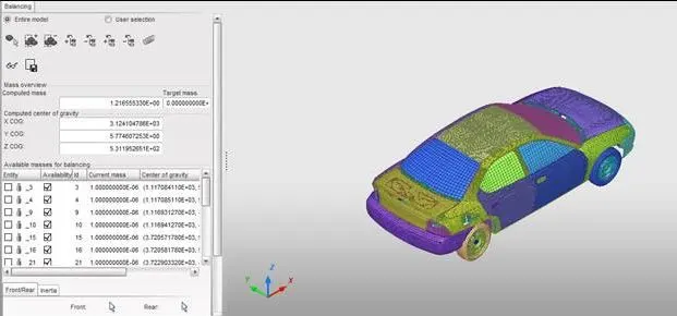
-But the weight for the model which we are going to use for our analysis is about 188.42 kgs and the model is shown below:
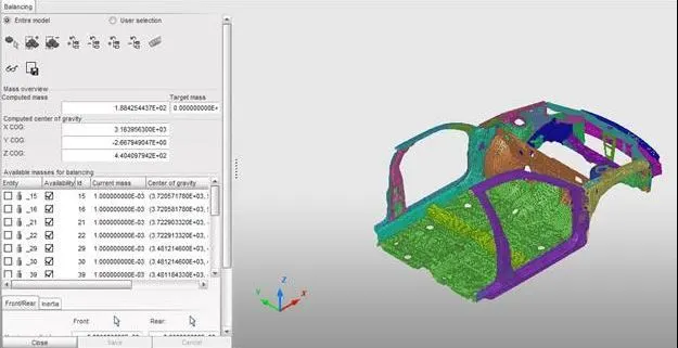
-Here we need yo balance the remaining weight with maximum limited value upto 700 kgs.
-Here we need to add up a extra weight of 511.69 kg to get the centre of gravity position near to the driver seat location line and to achieve this we add weight to the lower panel.
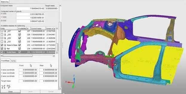
-So here we have added mass at bottom support,rail and nodes.(bottom weight=461.58 kg,rail=35 kg and to set of nodes=15kg).and totally the weight is achieved upto 700 kgs.
-The COG of the balanced mode is shown below:
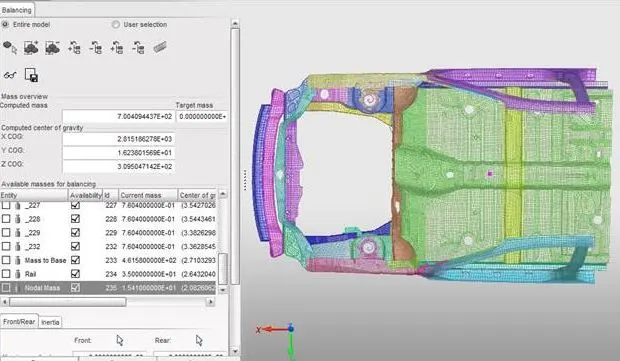
-To apply initial velocity of 35 mph:
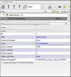
-Here in our system we are follow [kg mm ms] an there by here we need to inout the values in mm/ms.
-Here after converting the velocity of 35 mph=15.65 mm/ms.
-To give initial velocity to model in hyper crash go to load case>inital velocity>select the whole model and apply the velocity in X dierection as 15.65 mm/ms.
-To use model checker for ensuring the quality of model:
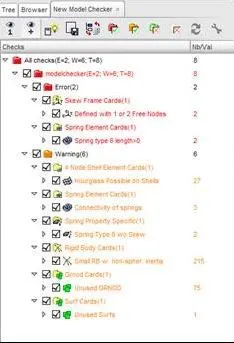
-Here we have to check model build quality before running the simulation.We can do it by performing the option Quality>model checker>Run.Now we will encounter some error we can rectify it by either clicking on auto correct tool or we have find it manually.
-Output Request:
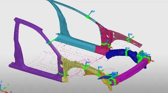
- Sectional force in the rails at location of indicated node 174247.
- Axial force received on the rails from bumper.
- Shotgun cross sectional forces.
- A pillar cross section.
- Acceleration curve received on the accelerometer at base of B pillar (on B pillar rocker).
- Intrusions on the dash wall 66695,66244.
-Now to get the force in the sections which are mentioned we need to create a section at those place.For performing those option Go to Data history>section>select components>select 3 nodes to create section.
-After runing the simulation we will get a popmenu as below:
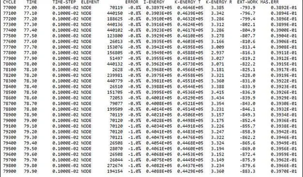
-Now before going for animationwe need to check for energy and mass error.From the above image we come to know that the energy error is -1.0% and mass error is 0.3970E-01 and now we go for graph plot and animated files.
Case 1: sectional force in the rails at the location of indicated node 174247.
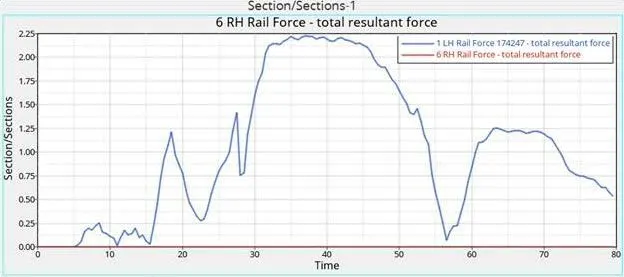
-Here we can see that sectional force in the left railk is 2.25 Kn where as sectional force right rail is nulified and finally comes to zero.
-The axial force received on rails from bumper:
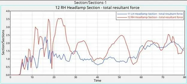
-From the above graph we can see that axial force in the LH region of rail is 2.48 kN where as axial force in the RH region of rail is 3.54 KN.Also we can say that the axia force at initail time is high compared to after step region.
-Short gun cross-sectional forces: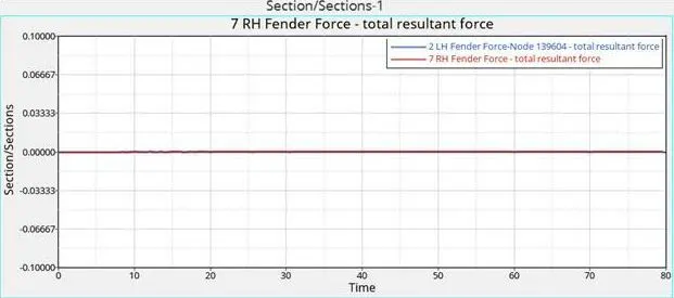
-Here in our case the whole impact on the model is distributed in the bumper and rails and the no force on shot gun nullifies and is 0 Kn.
-A pillar cross section force: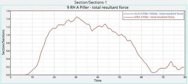
-From the graph we know that force are transfered to A pillar of the vehicle where in our simulation we can note that force at RH A pillar is more compared to LH A pillar(force in RH A Pillar is 1.4KN and LH A Pillar is 0 kN.
-Acceleration curve received on acceleration at base of B pillar (on B pillar rocker):
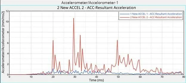
-From the above graph we can say that the accelemoter shown is around 10.50 mm/ms^2 in 2 New accel 2-ACC-resultant acceleration.
-Intrustions on the dash wall 66695,66244:
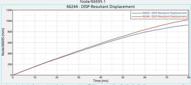
-From the above graph we can see that intrusion at 66695 is around 915mm and the intrustion at 66244 is around 1015mm.
-Energy on the model:
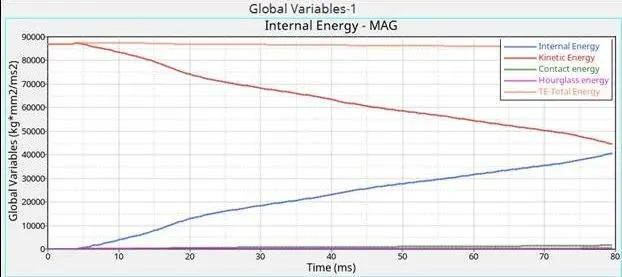
-The above graph shows us the various energy types of the model during the impact test.
Animataed file of model (.h3D)
frame 1:
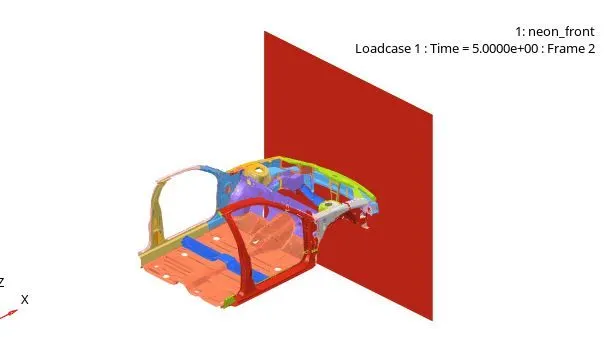
frame 2:
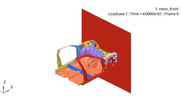
Frame 3: