Assignment 6
Aim:
Frontal crash-BIW
Check unit system and either follow[Mg mm s] or [Kg mm ms].
Create appropriate interface ,friction 0.2 and recommended parameters.
Make sure of no penetrations and intersection.
Correct rigid bodies if any issues.
Create rigid wall with friction 0.1.
Compare the model weight with the full scale 300k nodes model and use added masses to reach target weight 700kg while getting CG about the required range.
Initial velocity 35 mph.
Use model checker to ensure good quality.
Time-step :0.5 to 0.1 microseconds.
Run 80 ms.
Procedure:
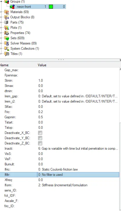
Create appropriate interface ,friction 0.2 and recommended parameters.
Importing the rad file for the process. The unit system is set as kg mm ms.
For clear the unwanted property from the model go to Model-> clear existing interface.
Now create the new contact-> neon front->card image as type 7.
To create the interface go to the group-> neon front(which was created)-> Gmod_id(S)(slave node)-> select the part to be slave node and ->Surf_id(M)(master node)-> select the part to be master node-> click ok.
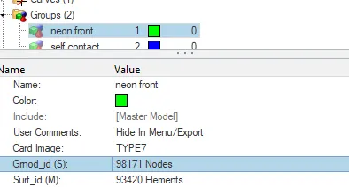
Now filling the recommending parameter and the friction value as 0.2
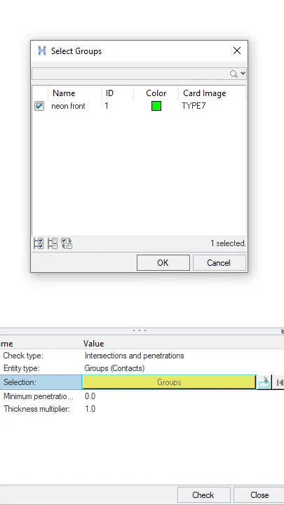
Make sure of no penetrations and intersection.
Now check the penetrations go to Tools-> Penetrations checker->Select group-> Check.
To check the connectivity go to Tools-> Find connectivity-> Select entities-> Component-> Check.
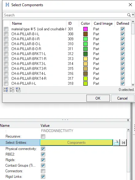
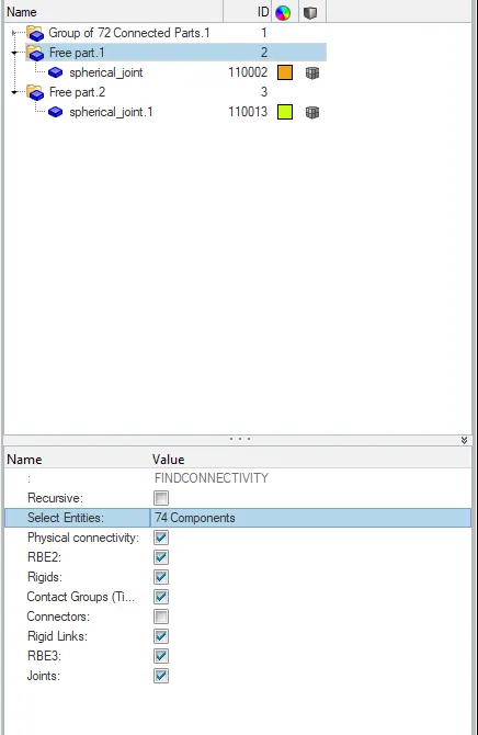
There are 2 free components identified in the system. Hence it is free part it can be deleted from the component.
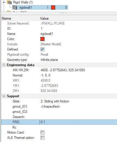
Create rigid wall with friction 0.1.
Creating the rigid wall-> right click create-> a rigid wall is created and a plot is graphed for the moment
Now creating the friction select-> side as (2: sliding with the friction)-> FRIC(0.1)

Added masses to reach target weight 700kg.
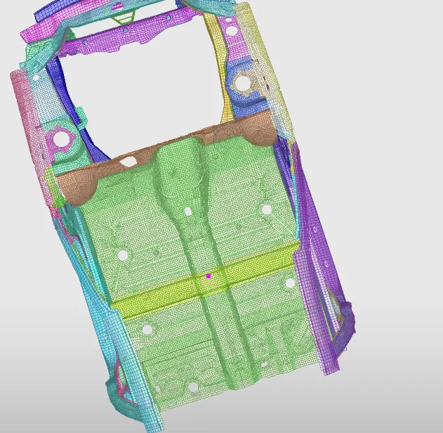
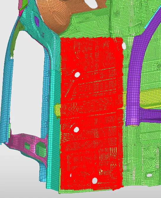
For adding the mass go to hypercrash-> load case-> Added mass->Click(type 1)-> select the areas separatly to give a distributed mass.
For balancing the mass go to Mass-> Balancing-> once mass is loaded for checking the balancing click  to check the balancing.
Type 1 is mass distributed to each node separately.
In this model four equal mass is created to each node to produce a perfect balancing.
Initial velocity 35 mph.
To open the solver go to View-> Browser-> Hypermesh-> Solver.
In solver-> right click create-> Boundary condtions->INIVEL.
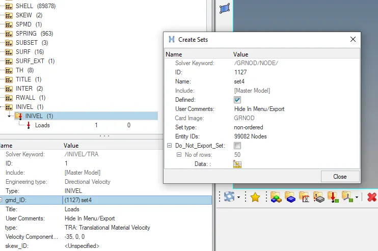
Now right click on gmd_ID-> Create/Edit-> there opens a block Create set-> Select the whole component and click ok. There appears selected node.
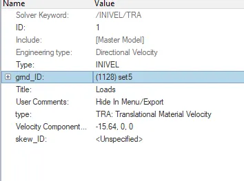
Now giving the initial velocity as 35mph. Converting the mph to mm/ms. We get 35mph as 15.64mm/ms.
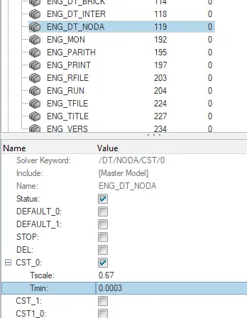
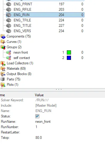
Time-step :0.5 to 0.1 microseconds. Run 80 ms.
For including the time step go to cards-> ENG_DT_NOTA-> Changing the values on Tmin.
In this process we have to change microsecond into milliseconds.
0.5microsecond - 0.0005milliseconds.
Now to choose the minimum values between the 0.1-0.5.
Sectional force in the rails at location of indicated node 174247.
For creating the sectional force go to Hypercrush-> Browser-> right click Section-> Basic field-> Frame_ID-> Create Frame-> Moving Frame.
Then filling the values of n1,n2,n3 from the frame created in node1,node2 and node3.
After that grshel_ID, select the section. After selecting the section click ok.
 this options helps to identify the node.
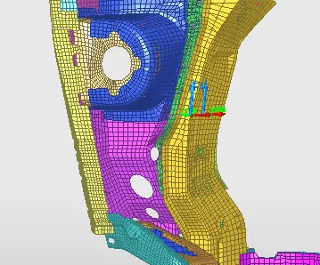
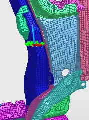
Axial force received on the rails from bumper.
For creating a interface contact go to browser-> right click-> contact interface-> Type 7.
Now typing the given parameter in the respective place.
Now to select the slave and master. To select the master node click Surf_id(M)-> right click-> Select in graphics-> Include pick parts.
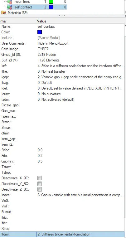
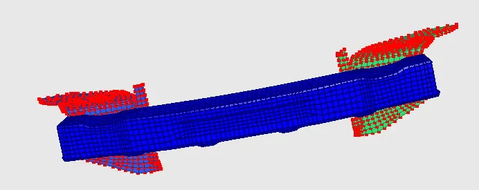
Shotgun cross sectional forces.
For creating the scetonal force go to Hypercrush-> Browser-> right click Section-> Basic field-> Frame_ID-> Create Frame-> Moving Frame.
Then filling the values of n1,n2,n3 from the frame created in node1,node2 and node3.
After that grshel_ID, select the section. After selecting the section click ok.
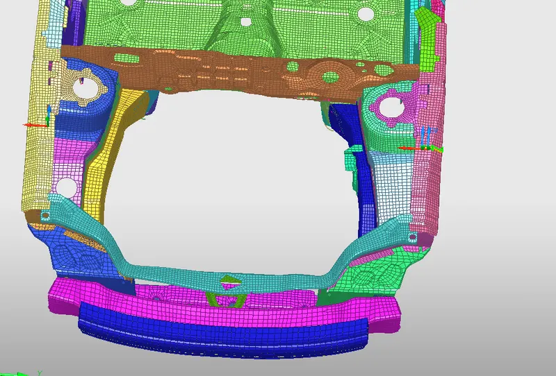
A pillar cross section.
For creating the scetonal force go to Hypercrush-> Browser-> right click Section-> Basic field-> Frame_ID-> Create Frame-> Moving Frame.
Then filling the values of n1,n2,n3 from the frame created in node1,node2 and node3.
After that grshel_ID, select the section. After selecting the section click ok.

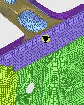
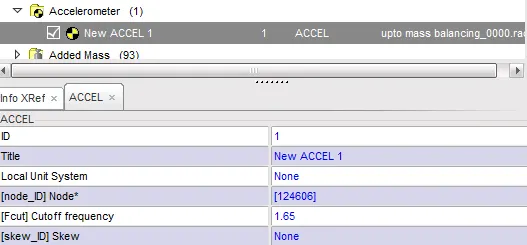
Acceleration curve received on the accelerometer at base of B pillar (on B pillar rocker).
To create a accelerometer right click on browser-> A-C-> Accelerometer.
Select the node to place the accelerometer.
Result:
Displacement
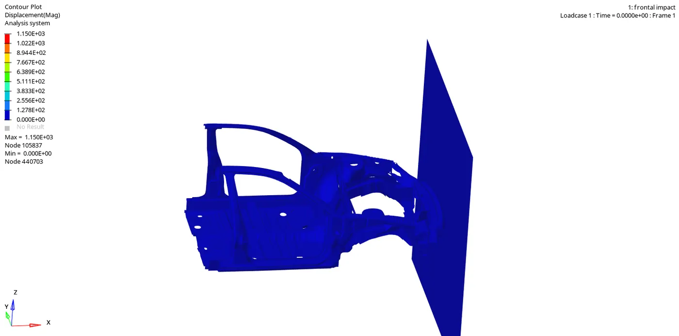
The contour plot is being plotted. The deformation occurs at the time of collision with the rigid wall. The collision the maximum displacement occurs at the node 105837 at the displacement of 1150.
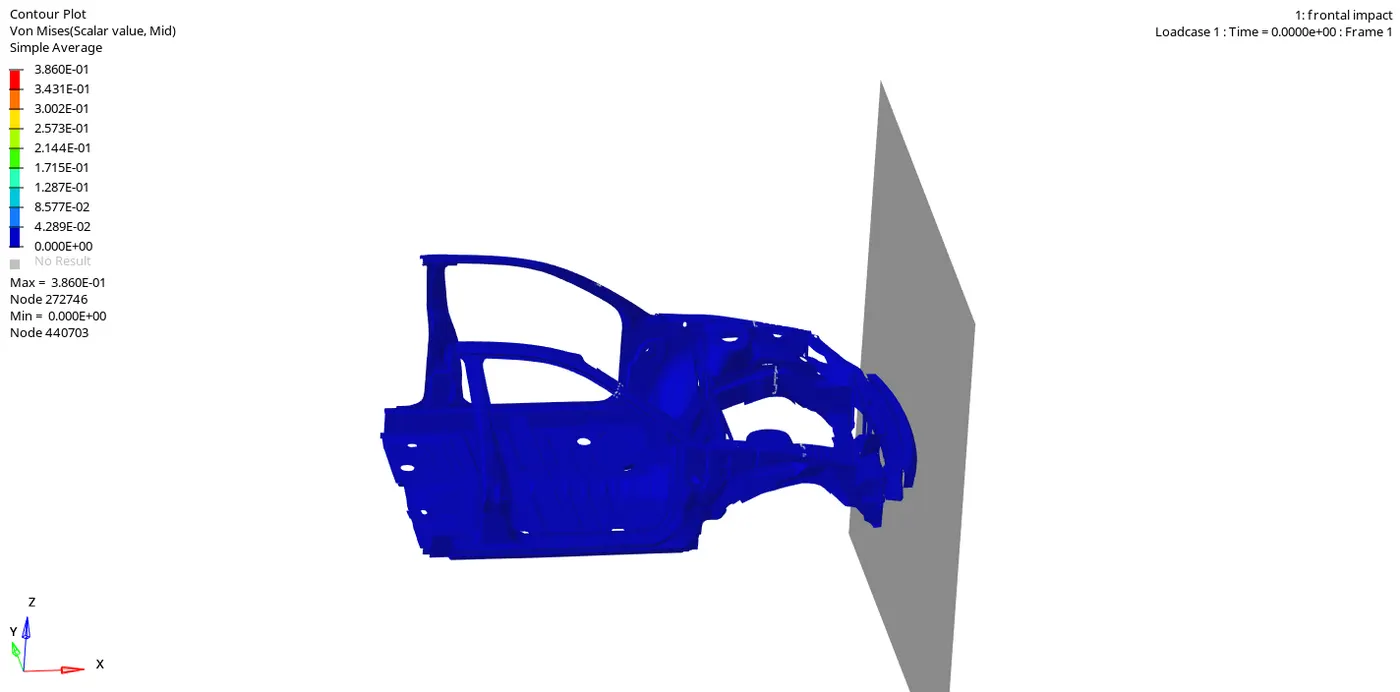
The contour plot is being plotted. The deformation occurs at the time of collision with the rigid wall. With the maximum stress developed the material behaves with the plastic deformation. The collision the maximum stress occurs at the node 272746 at 0.3860Gpa.
Axial force received on the rail from the bumper:
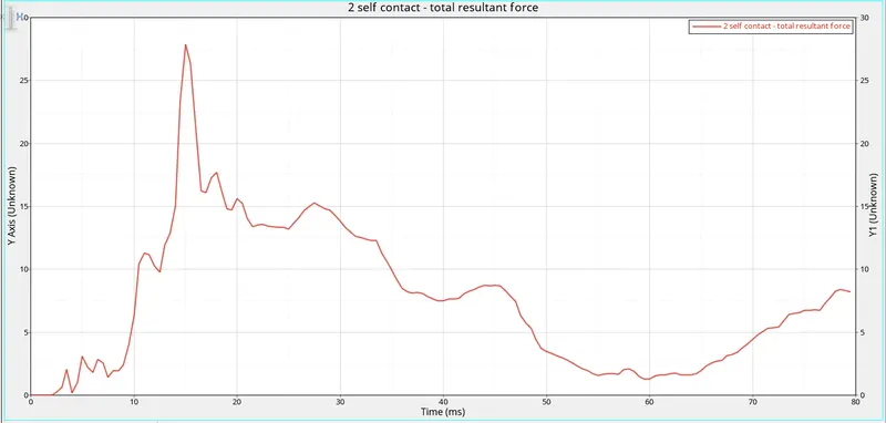
Before the deformation the material will be in normal condition.
When the deformation occurs the plastic range will be at 30KN at 16ms. After the time of 16ms the impact starts to travel to the other parts and measure the impact. Thus the contact force reduce as shown in the graph.
Shot gun:
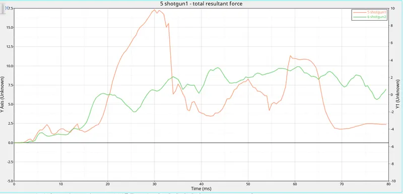
During the impact the impact force is transferred to all other body.
It is noted that the impact on the shotgun is less than the rail.
A pillar cross section:
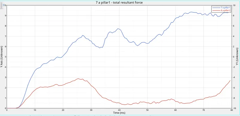
The deformation of the a pillar changes according to the point plotted at the pillar. The pillar does not deformes.
But according to the graph a pillar1 at 7.1KN at 29ms and a pillar2 at 2.8KN at 26ms.
Acceleration curve received on the accelerometer at base of B pillar
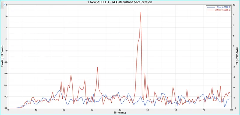
The accelerometer shows the impact towards the rigid body and the impact travel to the other parts.
The accelerometer 2 shows the impact force at 16.4kN at 46ms.
Intrusion on dash wall
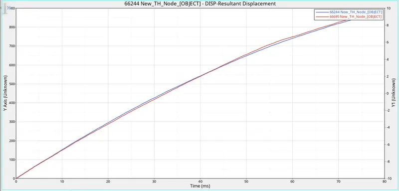
At the displacement curve the intial curve is increasing at the range of 800mm but after the impact occurs its again travels because of inital and final skew at 900mm.
Energy plot:
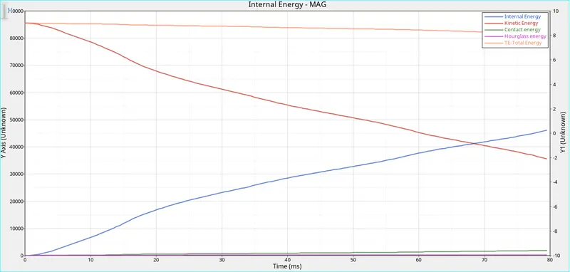
The hourglass energy and the contact energy stays at zero conditions. The hourglass is of because of QPEH element.
The kinetic energy is maximum during the impact and reduces after impact occurs.
The internal energy is minimum at starting and after the impact the flows increase because of plastic deformation.
Checking mass error and energy error

Conclusion:
From the Frontal crash BIM and the output request we have got all required values by inputing the given parameter.