Assignment 6
Objective: import the given model and perform frontal crash analysis by giving it required inputs and requesting required outputs by using tools in HyperWorks and hypercrash
Unit system:

Procedure:
1.import the solver deck
2. Under solver tab go to inter and delete everything under inter
3. Now create a new contact type7 under inter and name it

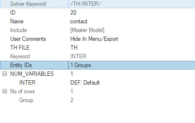
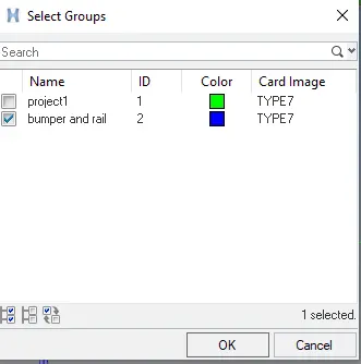
create another contact between bumper and rail and give recommended parameters as shown below
 here, the master is the bumper and the slave is the rest of the car
4. Right-click and isolate trias in SH3N and right-click show SHELL and BRICK
5. Now under the inter tab select G mod-id and select all the nodes and select Surface-id and select all the elements
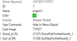 here master and slave are the entire model
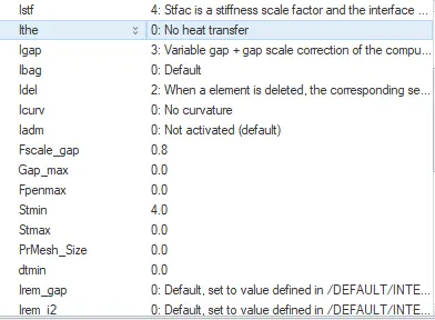
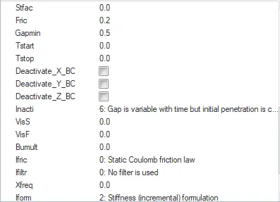
6. Give the recommended parameters for type7 contact
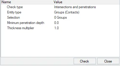
7. Go-to tool and check for penetrations
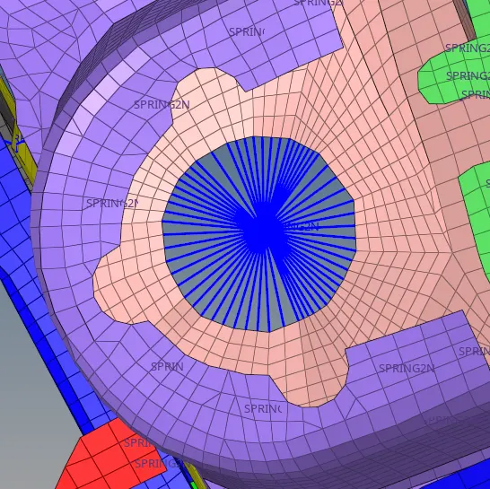
8. Now fix the rigid bodies in both the suspensions by going to 1-D--->rigids
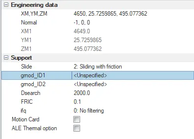
9. now create rigid wall(RWALL) and give fric as .1 and slide as 2(sliding with friction)
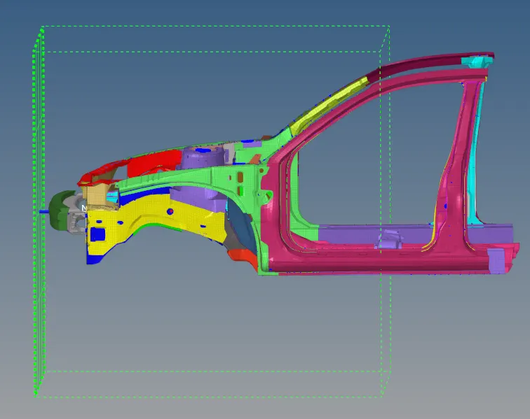
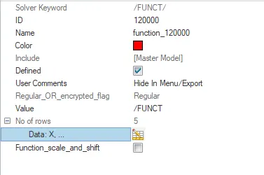
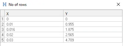
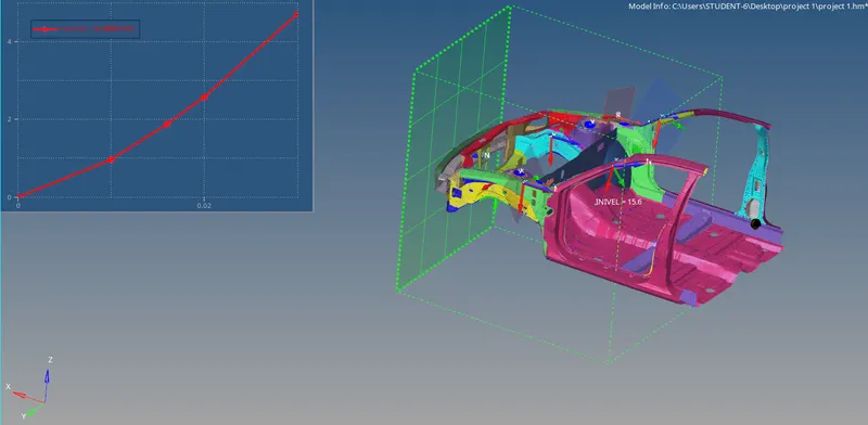
10. now right-click create---->boundary condition---->INIVEL to create inivel and give the valve 15.64 as per the question

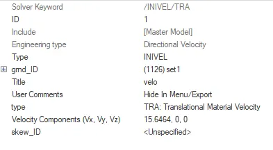 we assign the velocity by isolating the given node and place velocity in that node
11. Create frames by going to create---->frame--->MOV
here we create a local system and the origin node, axis node and the plane node will become the N1, N2 and N3 for sect
we create 6 frames (2 each for rail, shotgun, and A-pillar)
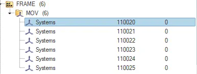
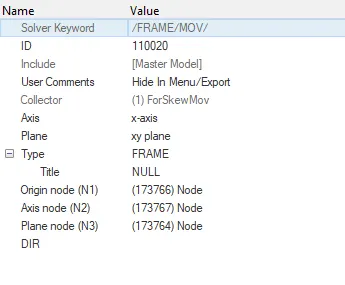
12. Go to the model tab and right-click and create set and select all the elements on the rows of the local system
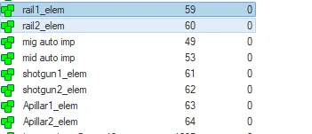
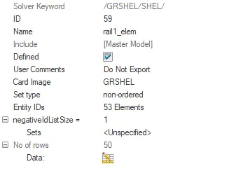
similarly, create 5 more sets for other cross sections also
13. Under solver create sections
solver---->section---->SECT
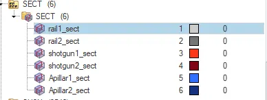
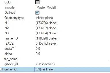
as I said earlier give the values of the local system and the origin node, axis node, and the plane node to N1,N2 and N3 under frame-id and select the local system created
assign the respective set to the respective sect under the grshell-id
14. Compare the model weight with the full-scale 300k nodes model and use added masses to reach target weight 700kg while getting CG about the required range.
Open hyper crash and export the current file from hyper crash and balance the 700kg throughout the car
import model---->go-to mass ---> balancing
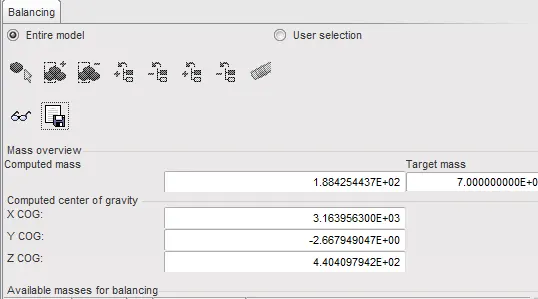 set target mass and then click load case and select added mass and choose the areas where you want the weight to be added
by clicking on the specs icon we can find out the centre of mass, keep adding mass until the weight is uniformly distributed.
once all the masses are added the computed and target mass should be almost equal
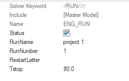
15. Under model open cards and click ENG_RUN and set run to 80.
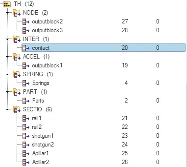
16. Now go to the solver and under TH create a total of 9-time histories to observe the output
one for contact (INTER), one for velocity(ACCEL) one for spring(PRING) and 6 for cross-sections(SECT)
Click on the group and assign the respective groups
17. Acceleration curve for the accelerometer set at the base of B-pillar rocker

18. Goto analysis, save the file and run radios (give -nt 4 to speed up the run time)

19. Once the animation is run and there are no errors we can observe the result
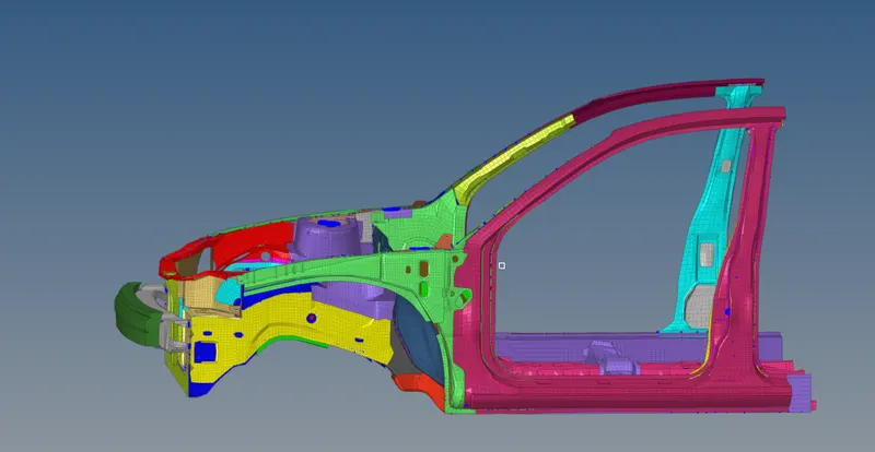
final model with all the modifications :
- Sectional force in the rails at the location of indicated node 174247.
- The axial force received on the rails from the bumper.
- Shotgun cross-sectional forces.
- A pillar cross-section.
- Acceleration curve received on the accelerometer at base of B pillar (on B pillar rocker).
- Intrusions on the dash wall 66695,66244.
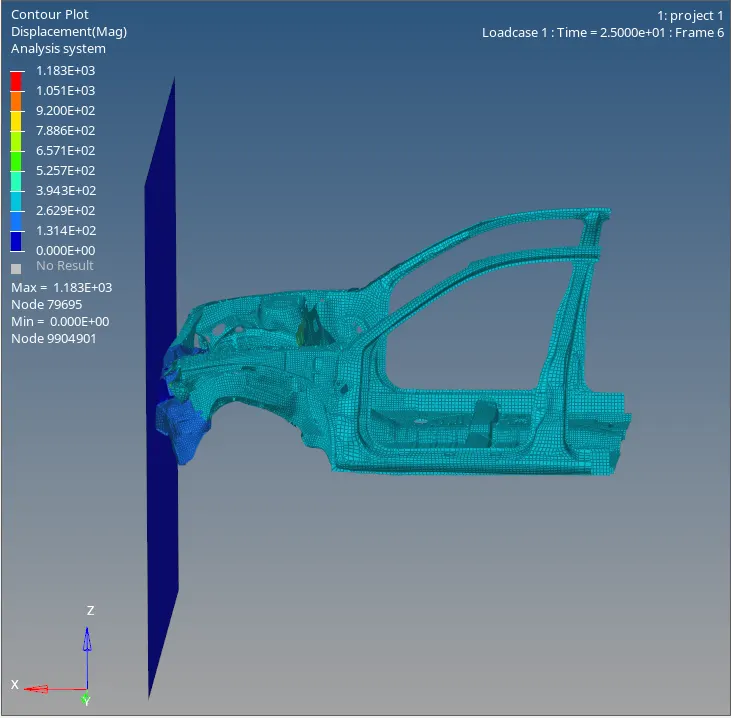
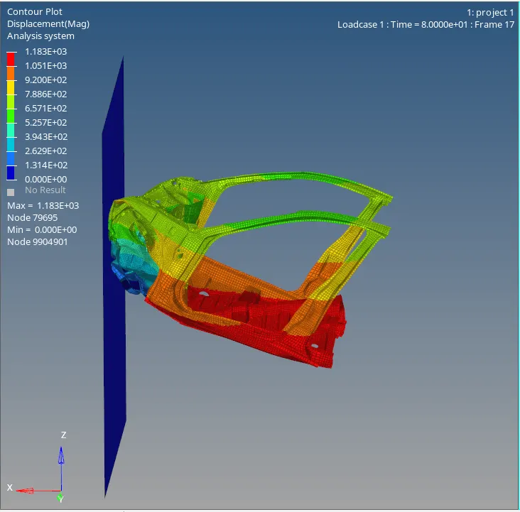
20.countor plot
frame 6 :
frame 17 :
Graph: rail 1 and rail 2
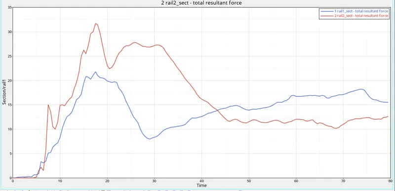
from the graph, we can observe that the right rail is receiving more force than its counterpart
there is a rise in forces at t=15 due to the initial crash
accelerometer :
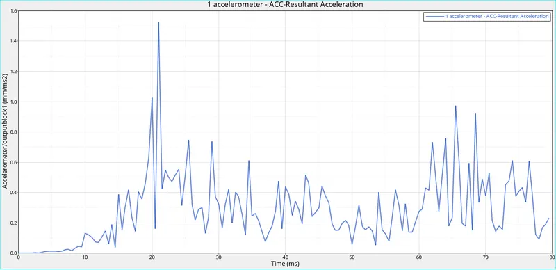
acceleration is high on impact and it gradually decreases slowly
A-pillar forces 1 and 2 :
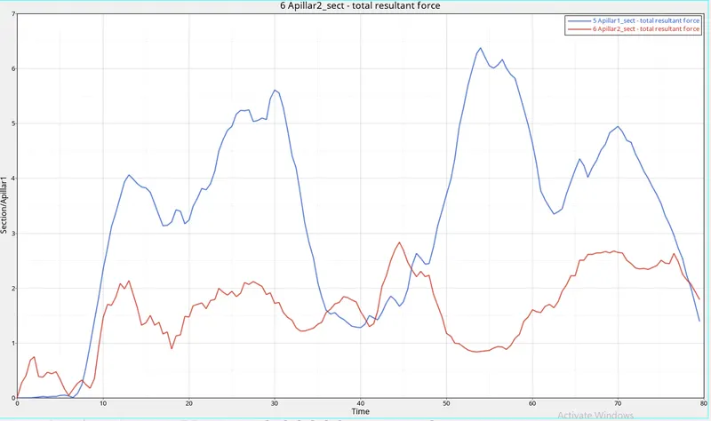
the forces on the 2nd A-pillar is high compared to the first A-pillar
the first rise in forces is due to initial deformation and the second rise is due to final deformtion
Shotgun forces 1 and 2 :
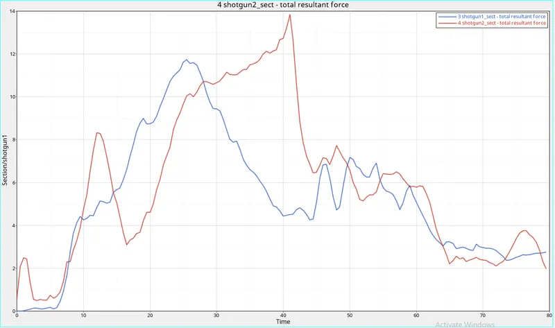
the maximum forces are acting on the first shotgun and it increases till 20ms
axis force on the bumper :
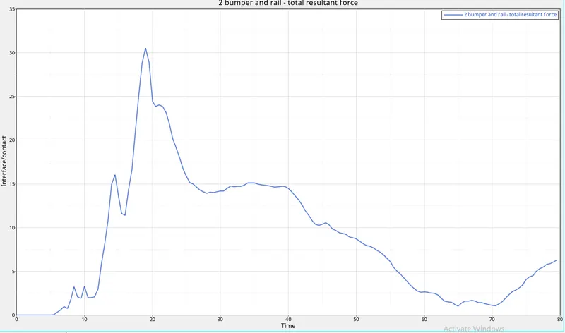
the forces increase in the start due to initial deformation and slowly decreases and rises a little again
conclusion :
more deformation of the vehicle on the left side has been observed
maximum deformation also observed on the right side but only at A-pillar
sectional forces are high on rails and second highest on the shotgun compared to A-pillar, this implies maximum forces are being transferred to rails and A-pillar
so if we increase the robustness of rails and A-pillar o the right side and A-pillar of the left side the occupants will be much safer
google drive: https://drive.google.com/drive/folders/1YenbWDSWhsso3HDowrU_L_oCbc3OnXp1?usp=sharing