Frontal Crash Neon BIW using Radioss
Aim
- To make frontal crash setup on Neon model car biw assembly
- Study it's various components
- Understand conditions to be applied for frontal crash
- Simulate and obtain output results
- Analyse the results and conclude
Objective
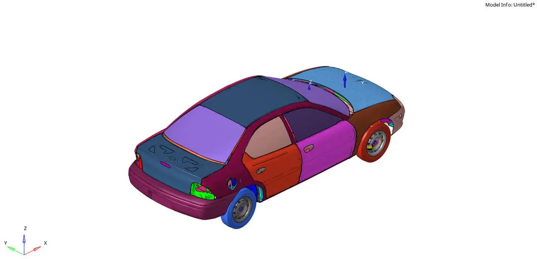
Frontal crash-BIW
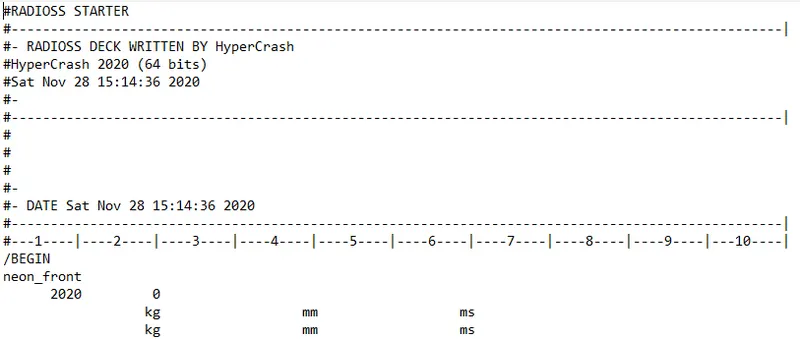
- Check unit system and either follow[Mg mm s] or [Kg mm ms].
- Create appropriate interface ,friction 0.2 and recommended parameters.
- Make sure of no penetrations and intersection.
- Correct rigid bodies if any issues.
- Create rigid wall with friction 0.1.
- Compare the model weight with the full scale 300k nodes model and use added masses to reach target weight 700kg while getting CG about the required range.
- Initial velocity 35 mph.
- Use model checker to ensure good quality.
- Time-step :0.5 to 0.1 microseconds.
- Run 80 ms.
Output requests:
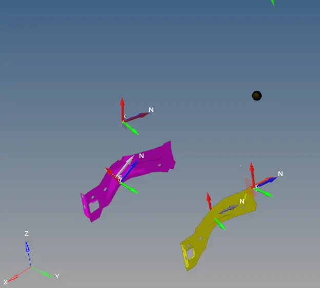
- Sectional force in the rails at location of indicated node 174247.
- Axial force received on the rails from bumper.
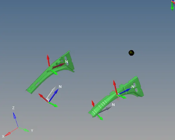
- Shotgun cross sectional forces.
- A pillar cross section.
- Acceleration curve received on the accelerometer at base of B pillar (on B pillar rocker).
- Intrusions on the dash wall 66695,66244.
Theory
BIW - Body in White
It is an assembly of frame and panels made of homogeneous materials
It is the stage in automobile where body shell structure sheet metal components are welded together in weld shop just before painting
Homegeneous - Composite of two metals like ; Aluminium and steel
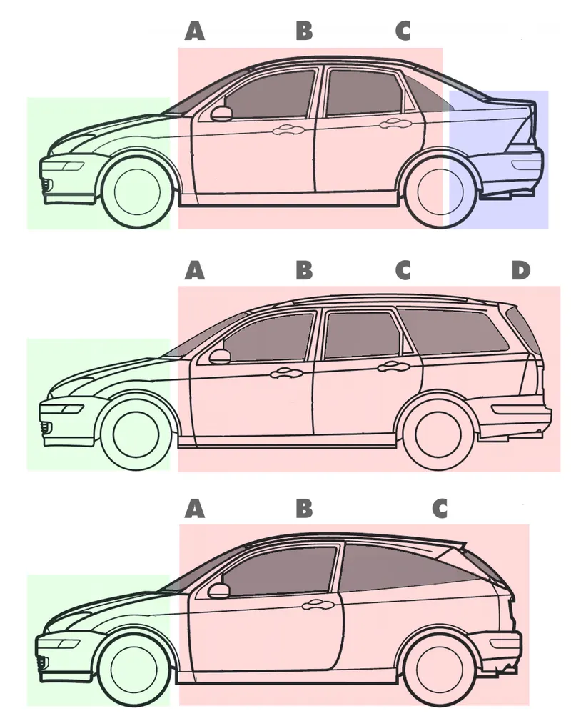
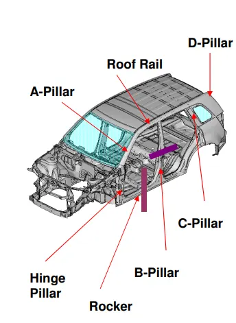
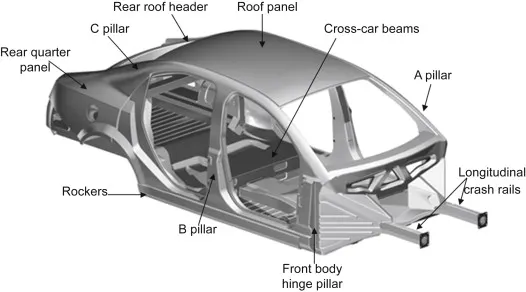
A Pillar - front most support to the roof
B Pillar - second most support to the roof
C Pillar - It is the rear most support to the roof; in case of two seating system it'll be third one
D Pillar - It is the fourth support can be find near rear side of quarter panel
Roof Headers - structural member above the windshield at juncture with the forward edge of the roof panel
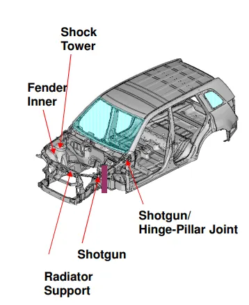
Shotgun - Main structural member absorbs part of crash energy, supports battery and other parts, transfers shock loads from shock tower to the body
Bumper - A horizontal bar fixed across the front or back of a motor vehicle to reduce damage in a collision
Rails - They are just behind bumper; they absorb the shock after bumper during crash
Section - A representation of the internal structure of something as if it has been cut through vertically or horizontally
Intrusion - sudden impact on a body
Accelerometer - An instrument for measuring the acceleration of a moving or vibrating body or nodes.
BIW Automotive Parts and its division
- A,B,C,D Pillars(Common)
•Dashboard mounting panel
•Windscreen & Rear Window rail
•Cant rail
•Roof structure
•Side Sill
•Upper quarter panel or window
•Front longitudinal member (acts as chassis)
•Front cross member
•Front & rear Valance
•Scuttle
•Firewall
•Floor, seat & Boot pan
•Front & rear Spring tower
•Central Tunnel
•Front & Rear Wheel arch
•Toe Board
•Heel Board
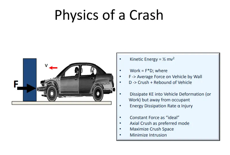
F = m x a
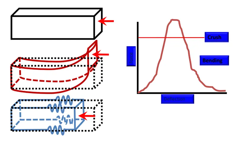
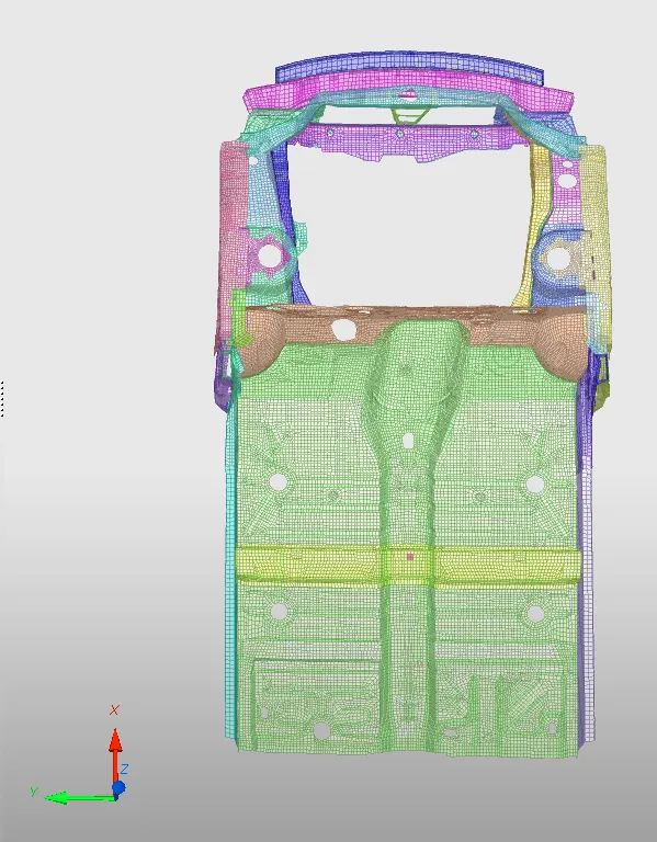
Structural deformation in Frontal Crash
Unit System
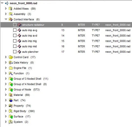
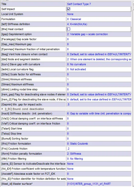
Contact Interface
Group wise contact was deleted and Self Contact- Type 7 was given with recommended properties
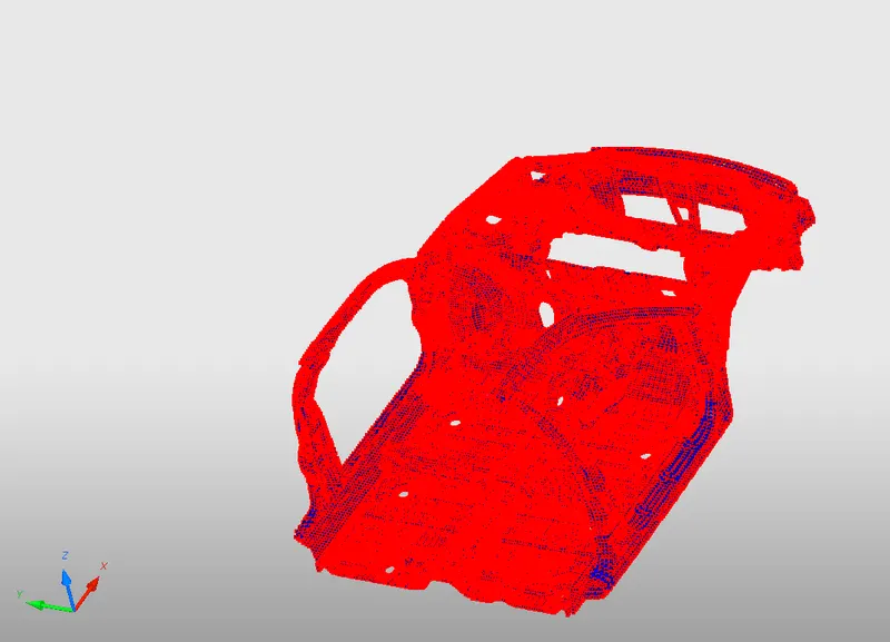
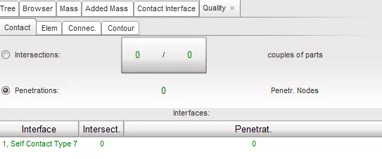
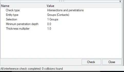
No Penetrations were found
Connectivity
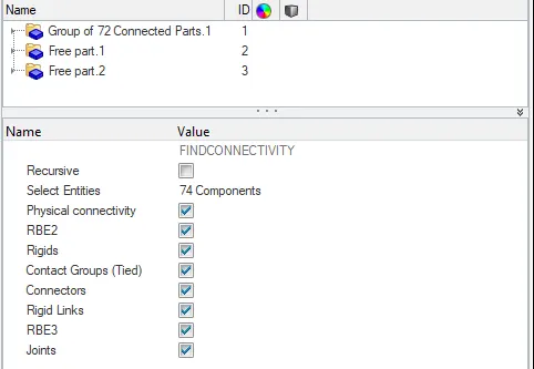
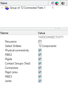
free parts are connected using spring 2N element and P13_SPR _BEAM Properties is created for the spring element
Rigid body issues correction
Spherical joints were found and deleted
Added Mass
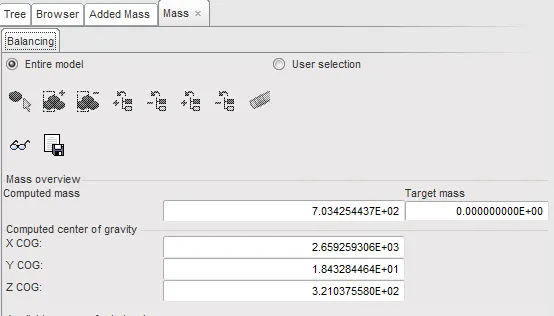
Centre of Gravity
A target mass of 700kg was achieved
Initial Velocity Condition
37 mph is given in ms - 15.6464ms
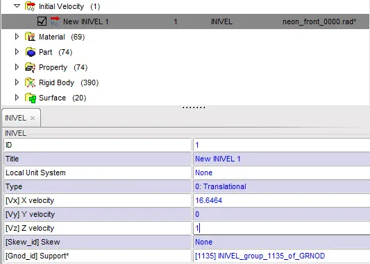
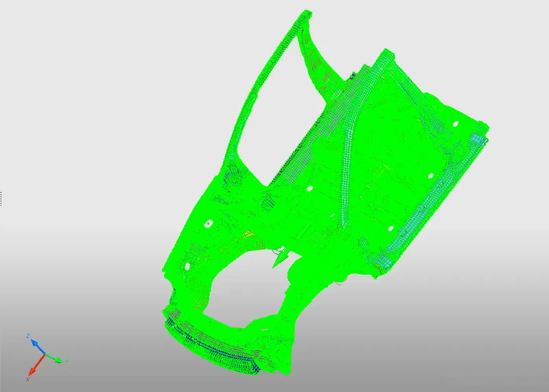
A Load collector of initial velocity is created along the Global X-axis with friction of 0.1 All thecomp[onents of the car body are selected using rectangle
Rigid Wall Conditions
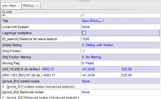
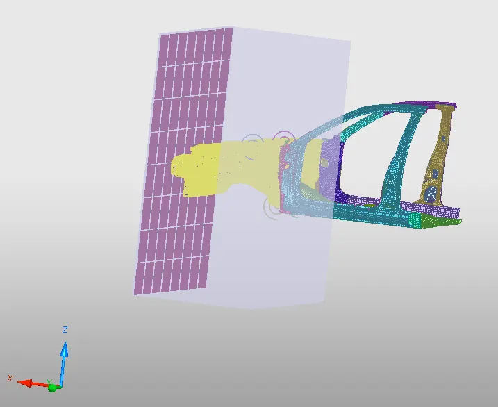
A rigid wall is created with some gap away from bumper
D_search of 1200mm till which impact takes place
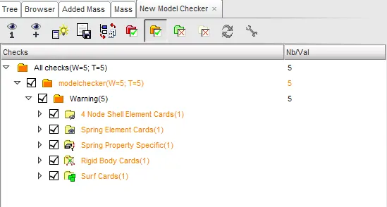
Model Checker
Errors were rectified
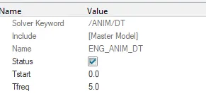
Engine cards of Timestep were defined
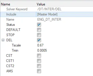
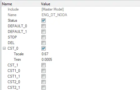
Section Creation
 Click on display Numbers -> Select nodes ->by id -> give no id and click on display -> Proceed
Create moving frame on rail
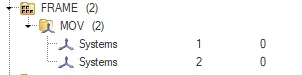
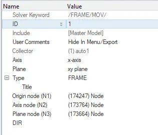
Create section using nodes and frame as reference
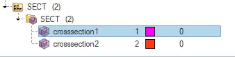
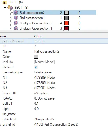
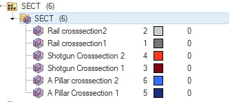
Create sets for cross sections and select elements
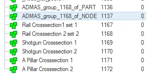
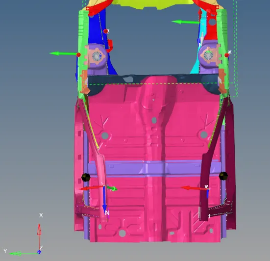
Accelerometers were defined
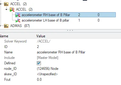
Base of B Pillar
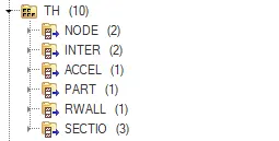
Time history card was defined
Axial force received on the rails from bumper
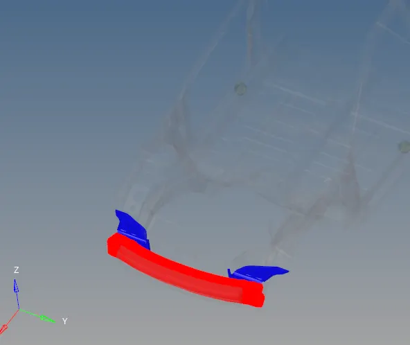
Type 7 contact was created to study axial force recieved on bumper with bumper as slave nodes and rail as master node
Ouptut result can be seen in TH Card
Acceleration curve received on the accelerometer at base of B pillar (on B pillar rocker)
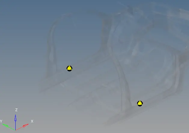
A pillar cross section.
Shotgun cross sectional forces
Sectional force in the rails at location of indicated node 174247.
Intrusions on the dash wall 66695,66244.
Intrusions on brake and Accelerator can be obtained
Post Processing
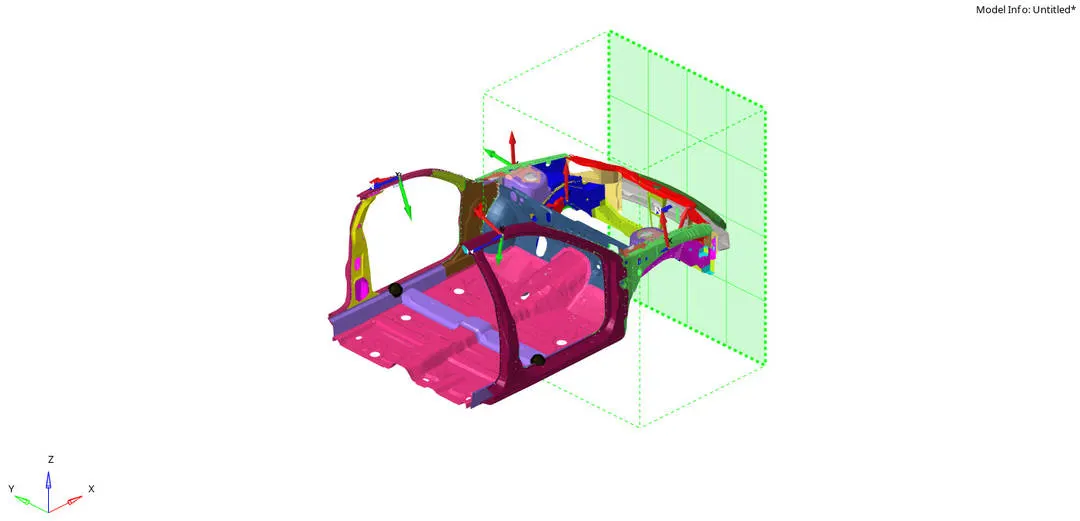
Model ready after giving all Frontal crash setup conditions
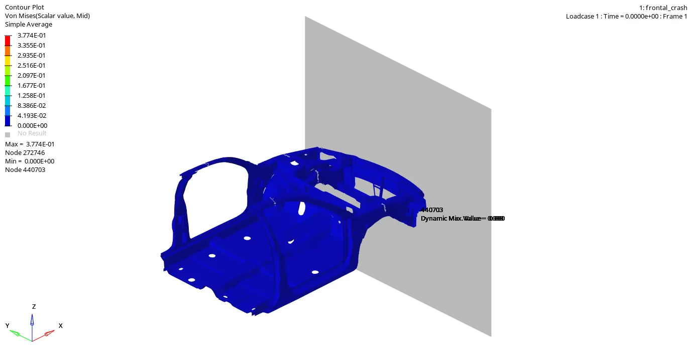
There is huge amount of deformation in the frontal area
Maximum Stress = 0.38 Gpa
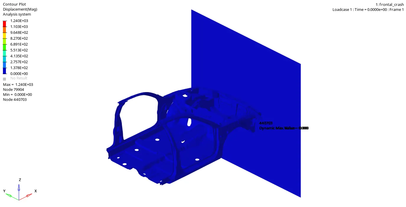
Maximum Displacement = 1240mm
The effect of dispalcement is till the rear portion of the car
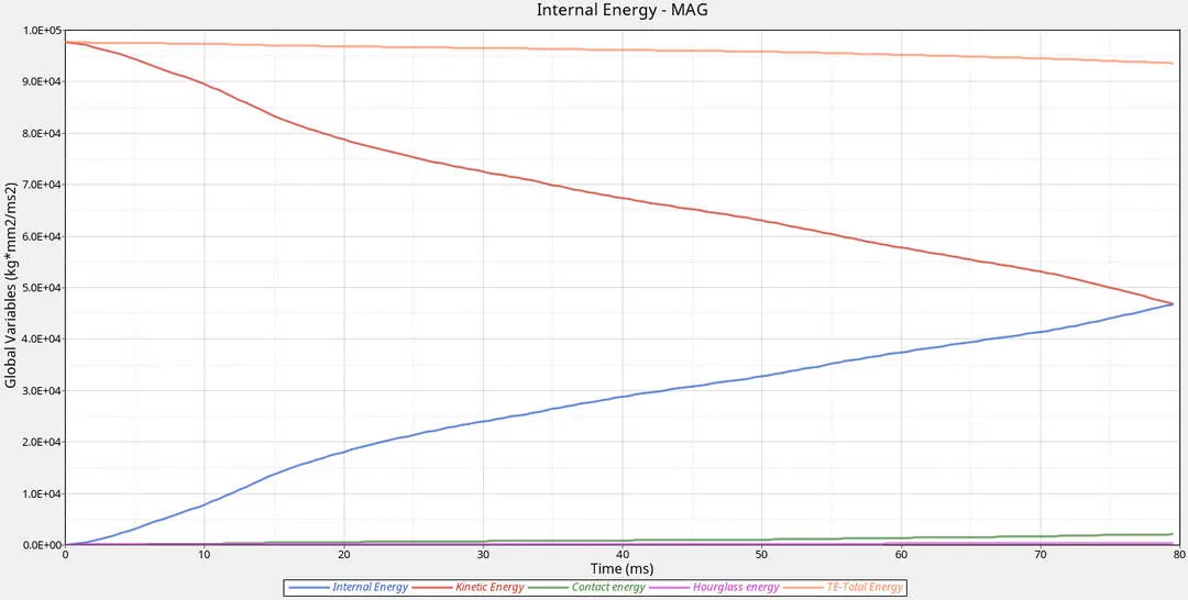
Inference
- Hourglass Energy is low due to element formulation QEPH = 24 and other recommended properties
- Initially there is high kinetic energy
- Internal energy and Kinetic energy become same at 79 seconds
- Total Energy is the sum of all energies
- Contact energy is less as the interference of slave node in master segment was less due to given contact interface (Type 7)
Sectional force in the rails at location of indicated node 174247.
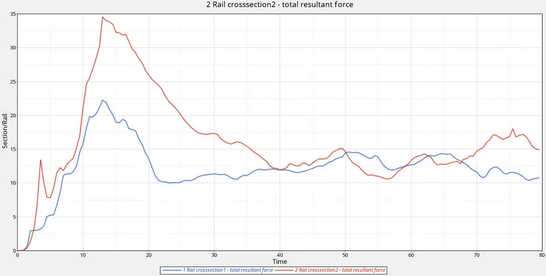
Inference
- The intial region of contact is frontal region(Bumper, rails)
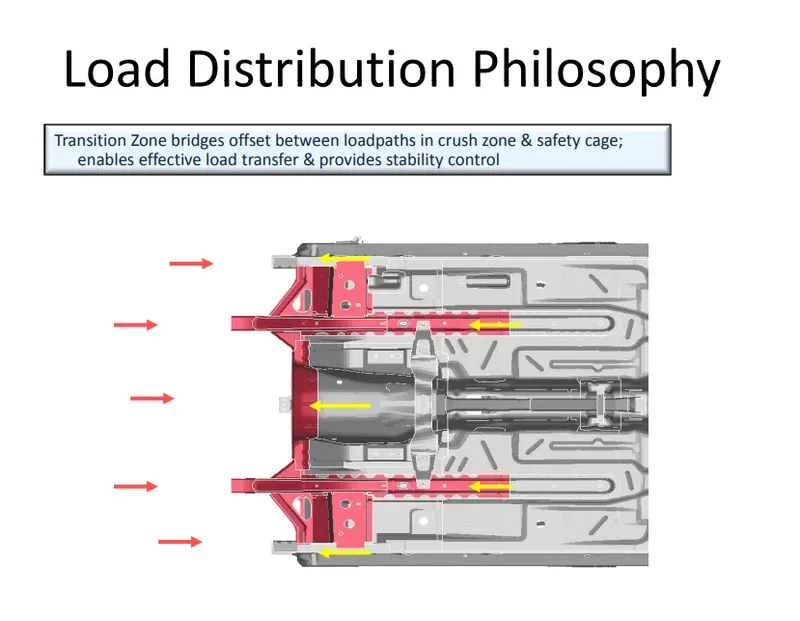
- It is the first get impacted and it is manufactured in a way to absorb more impact and reduce the impact on passenger
- It is the crumple zone
- Frontal rails absorb more impact compared to other components in frontal crash after bumper
- As in graph it can be seen sectional forces start after few seconds; becaused bumper is the first point of cantact
- There is difference in sectional forces between two rails
- 1 rail cross section is LH and 2 rail cross section is RH
- Force on RH rail is more than force on LH rail
- Sectional Force at Right Rail is 34kN >Sectional Force at Left Rail is 22.5kN
- The difference is due to following reasons
- C.G - Centre of gravity
- Node selection of rigid wall and rail
- Added mass distribution
- Sectional forces increase in Rh rail also shows that Rh rail has absorbed more impact
Axial force received on the rails from bumper
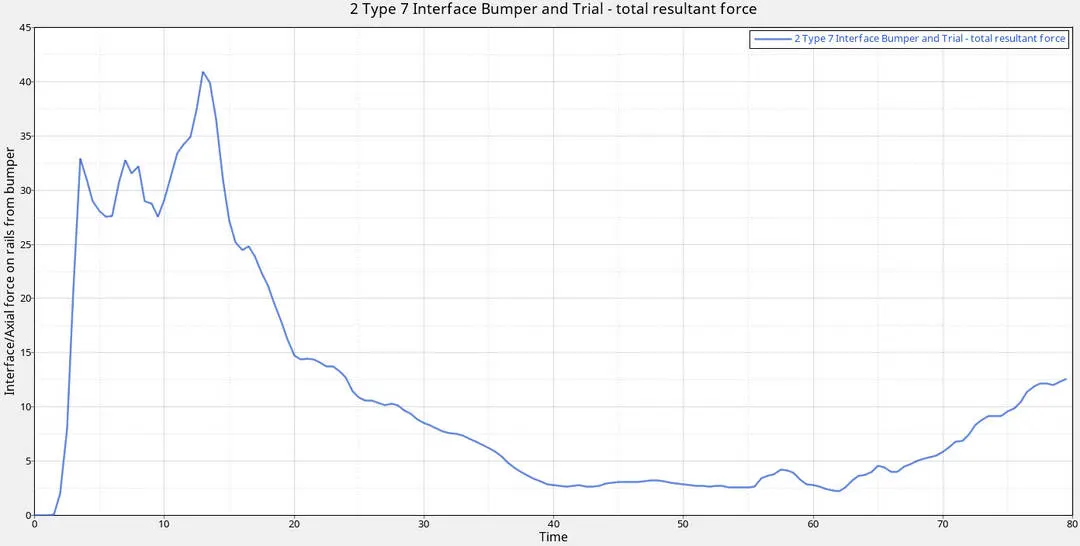
Inference
- From starting at 0.5ms there was high impact to 33kN
- As it can be seen in graph Bumper has absorbed high impact than any other component being first area to get impacted
- The high impact can been during 10ms to 14ms bumper has absorbed high impact of 41.5kN then gradually reduced; that means the area was crushed beyond plastic range
- There is again increase after 60ms and gradually decreasing.
Shotgun cross sectional forces
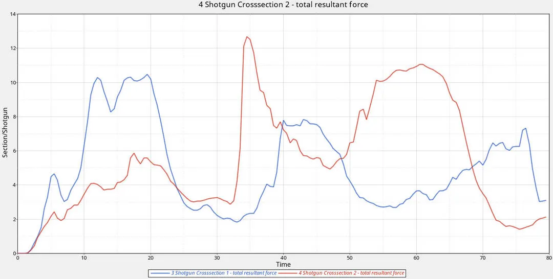
Inference
- Shotgun is just above rails connecting A- Pillar
- 3 Shotgun is Rh and 4 Shotgun is Lh
- Sectional force on Rh side is 10.5kN(peak) at 21ms and on Lh side is 12.7kN(peak) at 32ms and force has reduced gradually which means deformation has occured.
- After bumper and rails shotgun endure high impact; ensure that less impact is done on A pillar and other sub assemblies
- There is slight variation in sectional forces between Rh and Lh Shotguns; which means Lh shotgun has absorbed more impact than Rh, it also based on section-node selection
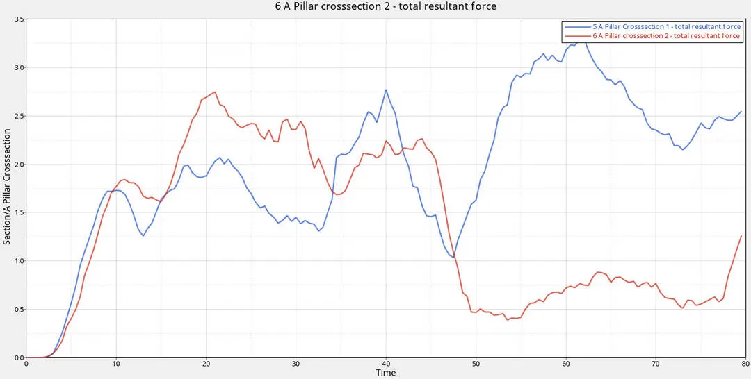
Resultant force on B Pillar
Inference
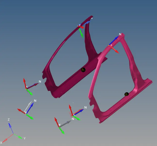
- 5 A pillar is Lh side and 6 A pillar is Rh side
- Sectional force on Lh side at peak is 3.25kN at 62ms and on Rh side at peak is 2.7kN at 22ms.
- As it can be seen the impact as reduced compared to Bumper, rails and Shotgun forces as most of the forces were absorbed at initial stages of impact
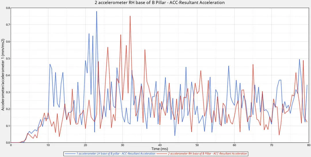
Acceleration force on B Pillar
Inference
- B- Pillar is the region where occupants are seated
- Using Accelerometer acceleration at the nodes on B-Pillar is obtained
- At Lh side value is 0.78mm/ms^2 and at Rh side is 0.75mm/ms^2
- Peak acceleration value at Lh side and Rh side are almost same with slight variation
- Acceleration value at these nodes is less as most of the impact is absorbed in earlier stages of impact
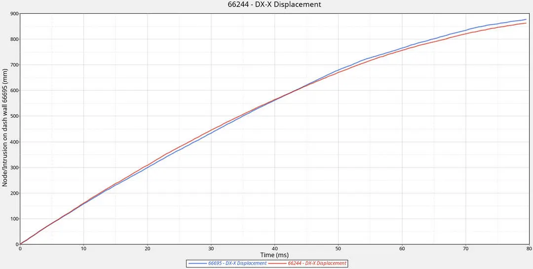
Intrusions on the dash wall 66695,66244
Inference
- Intrusions at braking and acceleration nodes are pretty high almost 850mm of displacement at 80ms
- Intrusions are due to improper balancing of mass and precense of engine components mass can be balanced
- Then intrusions can be diverted towards Engine area which can sustain intrusions
- Material quality near area of those intrusions can be improved to reduce intrusions
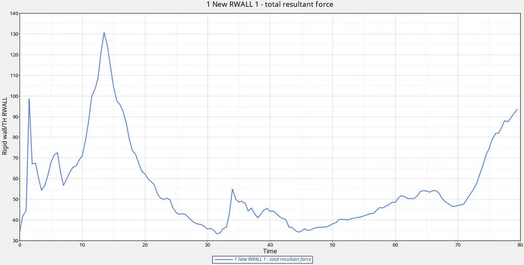
Rigid wall forces
Inference
- The Resultant force is 130kN peak value at 15ms just after collision with bumper
- After some time at 30ms it spiked slowly till 55kN and then reduced.
- At 70ms forces on rigid wall increased to 95kN at 80ms
- Variation in forces on rigid wall due to impact of different components on that come into contact based on D_Search value and material property.

Conclusion and Result
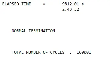
- -2.4% is acceptable as it is within limits as the Energy error can be between Positive(1% to 2%) Negative(-15%)
- Mass Error 0.001362 which is less than 1% is acceptable ; as the mass error can be between (1% to 3%
- Components on the front like bumper and rails are manufactured in a way absorb more impact so that the impact on passenger is minimized as possible
- Frontal crash setup was done and executed
- Post processing was done
- Inference on various forces acting during front impact was done
References
https://web.iitd.ac.in/~achawla/course_pdfs/4.%20MEL736/11-Crash_Safety_practices.pdf
https://www.slideshare.net/AjaykumarKalapu/biw-with-definitions
https://sites.google.com/site/bodyiinwhite/biw-body-in-white/what-is-biw
https://sites.google.com/site/impactabsorbtion/forces-within-a-crash