Frontal Crash Analysis with Guidelines of FMVHSS 208 Standard by using Radioss
Frontal crash-BIW
- Check unit system and either follow[Mg mm s] or [Kg mm ms].
- Create appropriate interface ,friction 0.2 and recommended parameters.
- Make sure of no penetrations and intersection.
- Correct rigid bodies if any issues.
- Create rigid wall with friction 0.1.
- Compare the model weight with the full scale 300k nodes model and use added masses to reach target weight 700kg while getting CG about the required range.
- Initial velocity 35 mph.
- Use model checker to ensure good quality.
- Time-step :0.5 to 0.1 microseconds.
- Run 80 ms.
Output requests:
- Sectional force in the rails at location of indicated node 174247.
- Axial force received on the rails from bumper.
- Shotgun cross sectional forces.
- A pillar cross section.
- Acceleration curve received on the accelerometer at base of B pillar (on B pillar rocker).
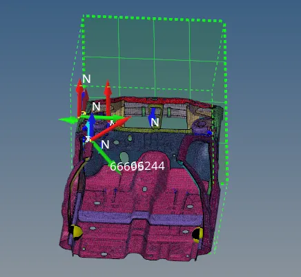
- Intrusions on the dash wall 66695,66244.
SOLUTION:
- Import File neon_front_0000.RAD
- Open RAD File to check the unit system
- Unit system being followed is Kg | mm | ms
- Go to Model > Groups > Clear existing interfaces present.
- Create new contact > Include neon_front > Card Image as Type 7
- Use Recommended Crash application data,

- Select Master Elements and Slave nodes to the type 7 interface.
- Friction value as 0.2
- Go to Tools > Penetration Checker > Check
- Check for the errors present
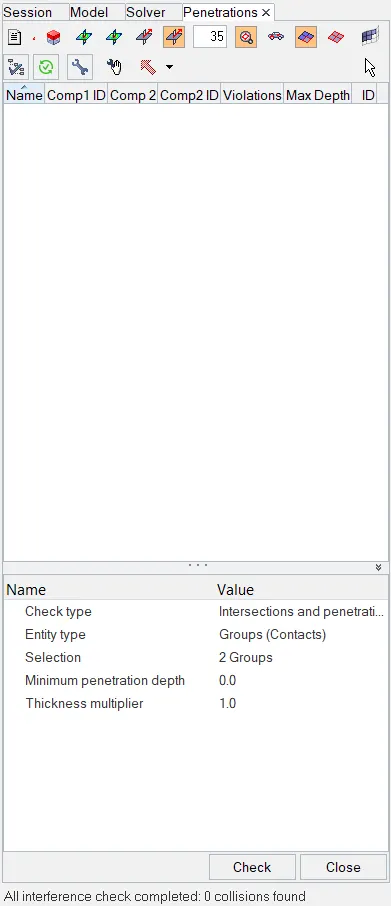
- There are no errors present in the model
- To Correct rigid bodies if any issues.
- Tools > Find connectivity > Check
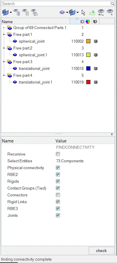
- There are 2 Free components present in the system , identified as Translational joint 1, TranslationaL_Joint 2 Spherical joint 1 & Speherical joint 2.
- Since those are free parts which is not required and can be cleared from the component
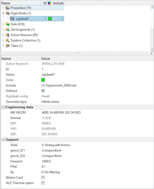
- To create rigid wall with friction of 0.1, go to Create > Rigid Walls.
- Using node, select the point to create reference point for the infinite plane.
- Use normal option to create the direction of the wall to act.
- Select Slide > Sliding with friction.
- Dsearch is used to induce the search distanct of the master to act upon.
- Input the friction value as 0.1
- To add mass to the model, target weight 700kg while getting CG about the required range
- Export file into radioss
- Go to Applications > Hypercrash
- set units as set in Hyper mesh as mm | Kg | ms > Run
- Click on added mass to view masses added on model
- To view COG , Go to Mass > Mass Balancing.
- To add mass Go to added mass section, Go to create new object
- Select Type 1 - Mass distribuited to each node of node group.
- In added mass input mass to be added, and select the nodes using selection.
- click save
- Go to Mass tab and click on view to preview COG
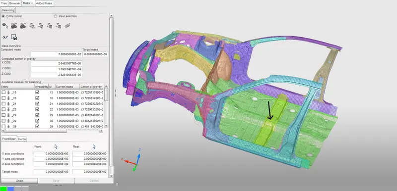
- Export the file as .RAD File to reopen in Hyper mesh
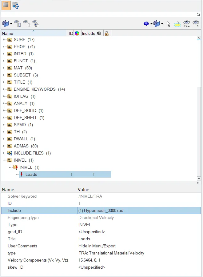
- To create the initial velocity 35 mph.
- Go to in Solver section > Boundary conditions > Inivel
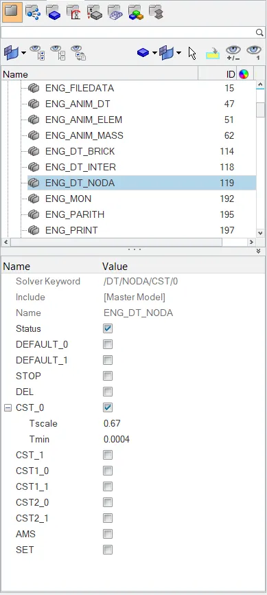
- To change Time-step between 0.5 to 0.1 microseconds.
- Go to Model > Cards > ENG_DT_NODA
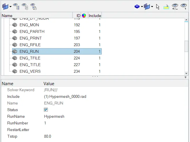
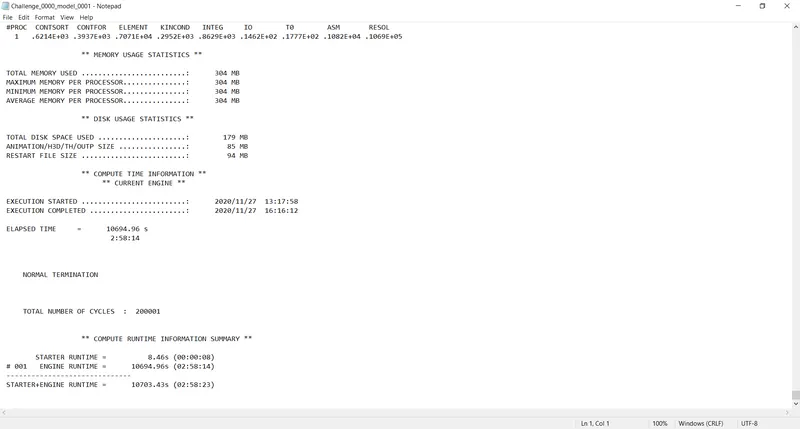
- To run Run 80 ms.
- To change Time-step between 0.5 to 0.1 microseconds.
- Go to Model > Cards > ENG_RUN
- To find Sectional force in the rails at location of indicated node 174247.
- Locate
 (Display Numbers) Click on node options type node ID 174247, press enter and turn on display
 - Go to Solver tab > Create > Frame > Movinf Frame > Choose nodal point such that Z axis is normal
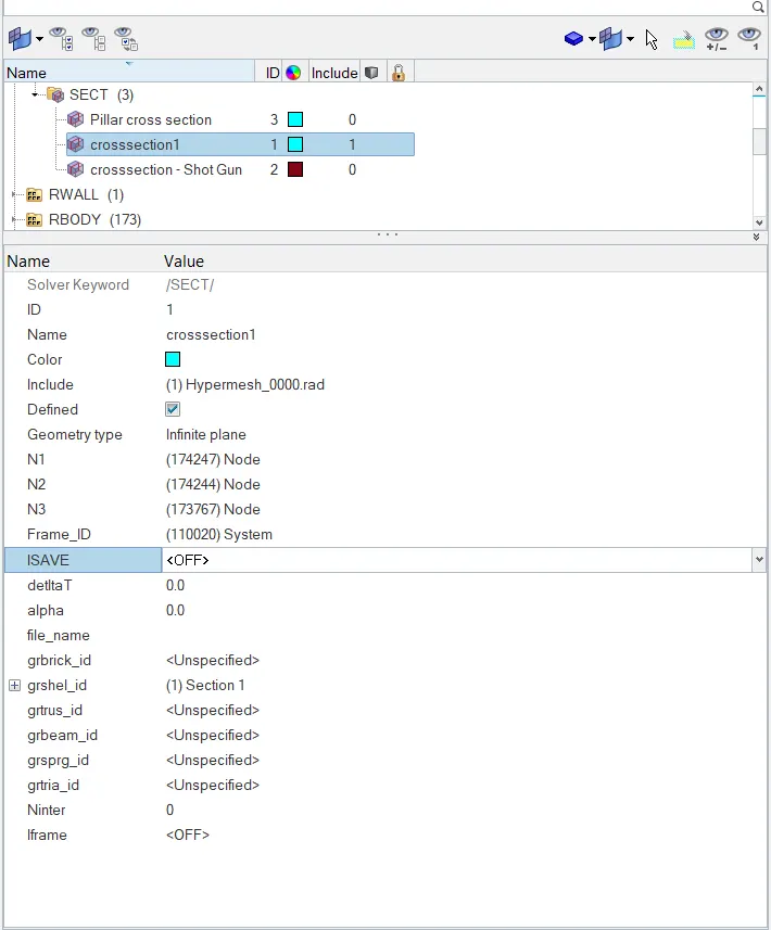
- Go to model tab > Set > Section 1 > Select the elements to be sectioned.
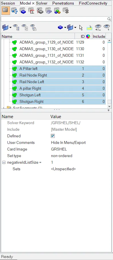
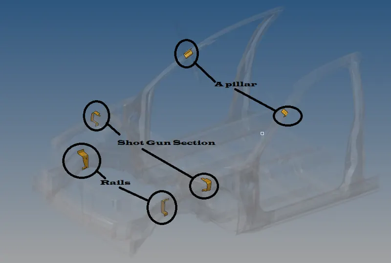
- Go to Create > Section > In cross selection, select the nodal points placed in frame > select frame ID
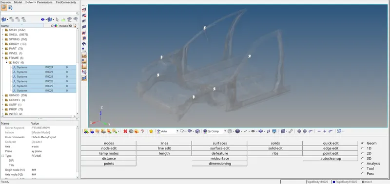
- Go to Time History > Create >Section > Select entity as Rail section
- Follow this procedure for all the cross section to be made in, shotgun section, Rails, A pillar.
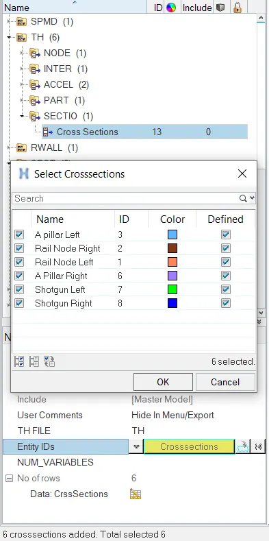
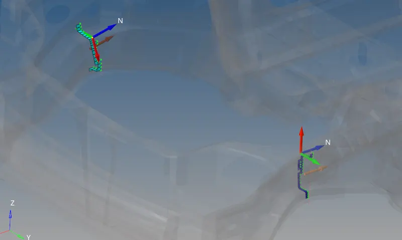
Rail cross section
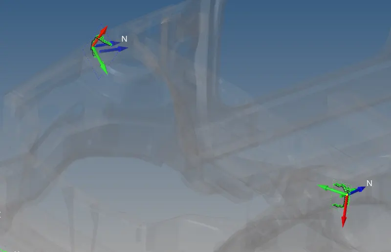
- To find Shotgun cross sectional forces.
- Go to Solver tab > Create > Frame > Movinf Frame > Choose nodal point such that Z axis is normal in short gun region
- Go to model tab > Set > Section Shot gun > Select the elements to be sectioned.
- Go to Create > Section > In cross selection, select the nodal points placed in frame > select frame ID
- Go to Time History > Create >Section > Select entity as Section shot gun
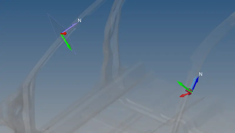
- To find A pillar cross section.
- Go to Solver tab > Create > Frame > Movinf Frame > Choose nodal point such that Z axis is normal in short gun region
- Go to model tab > Set > Pillar cross section > Select the elements to be sectioned.
- Go to Create > Section > In cross selection, select the nodal points placed in frame > select frame ID
- Go to Time History > Create >Section > Select entity as Section pillar cross section
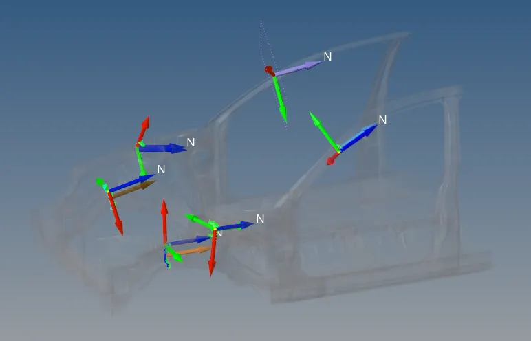
All the sectional Frames
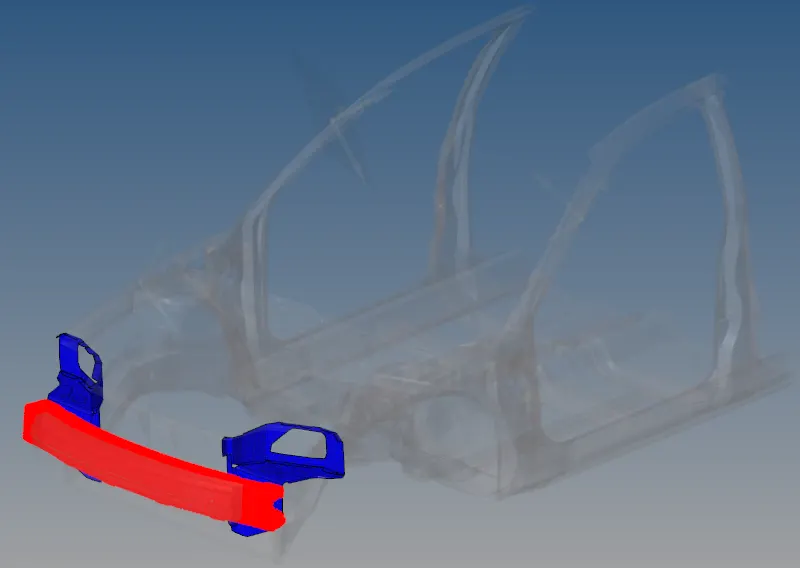
- To create Axial force received on the rails from bumper.
- Go to Model > Groups > Create
- Card type as Type 7 > Select Bumper parts as Slave nodes > Other components apart from bumper as car.
- Go to Solver Tab > TH > Select Entity > Axial contact.
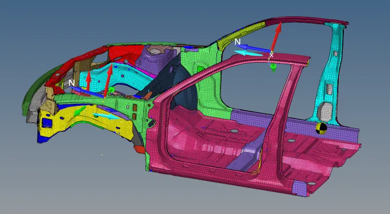
- Acceleration curve received on the accelerometer at base of B pillar (on B pillar rocker).
- Go to Model tab > Create > Accel
- Place a node on B pillar on which accelerometer to be placed.
- Go to TH Create > Acc > In entity select Accelerometer > Right Side ACC
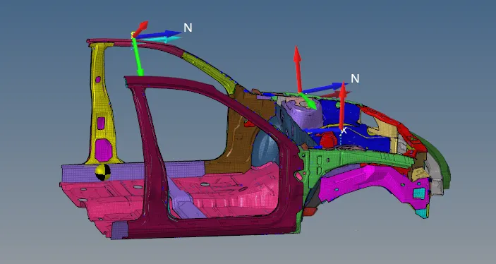
- Acceleration curve received on the accelerometer at base of B pillar (on B pillar rocker).
- Go to Model tab > Create > Accel
- Place a node on B pillar on which accelerometer to be placed.
- Go to TH Create > Acc > In entity select Accelerometer > Left Side ACC
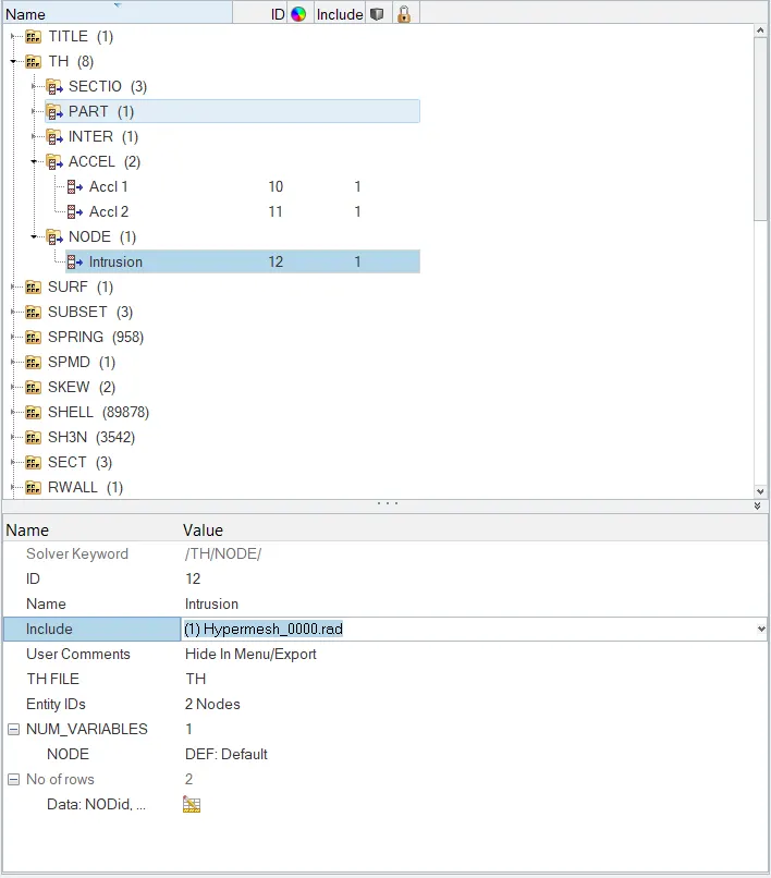
- Intrusions on the dash wall 66695,66244.
- Using Temp nodes > create node using ID > Add nodes
- Go to Solver > TH > Nodes > Specify for displacement > Select the nodes
Go to model checker > Check for defects
- Go to Tools > Model checker
- Click check option to Run the scan
- clear the parameters that failed.
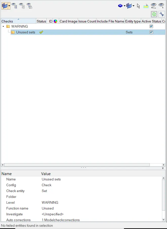
Ensure there are no errors founds in Model Checker.
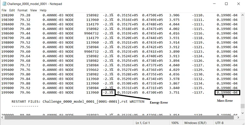
OUTPUT SCREEN:
HYPERVIEW SIMULATED OUTPUT :
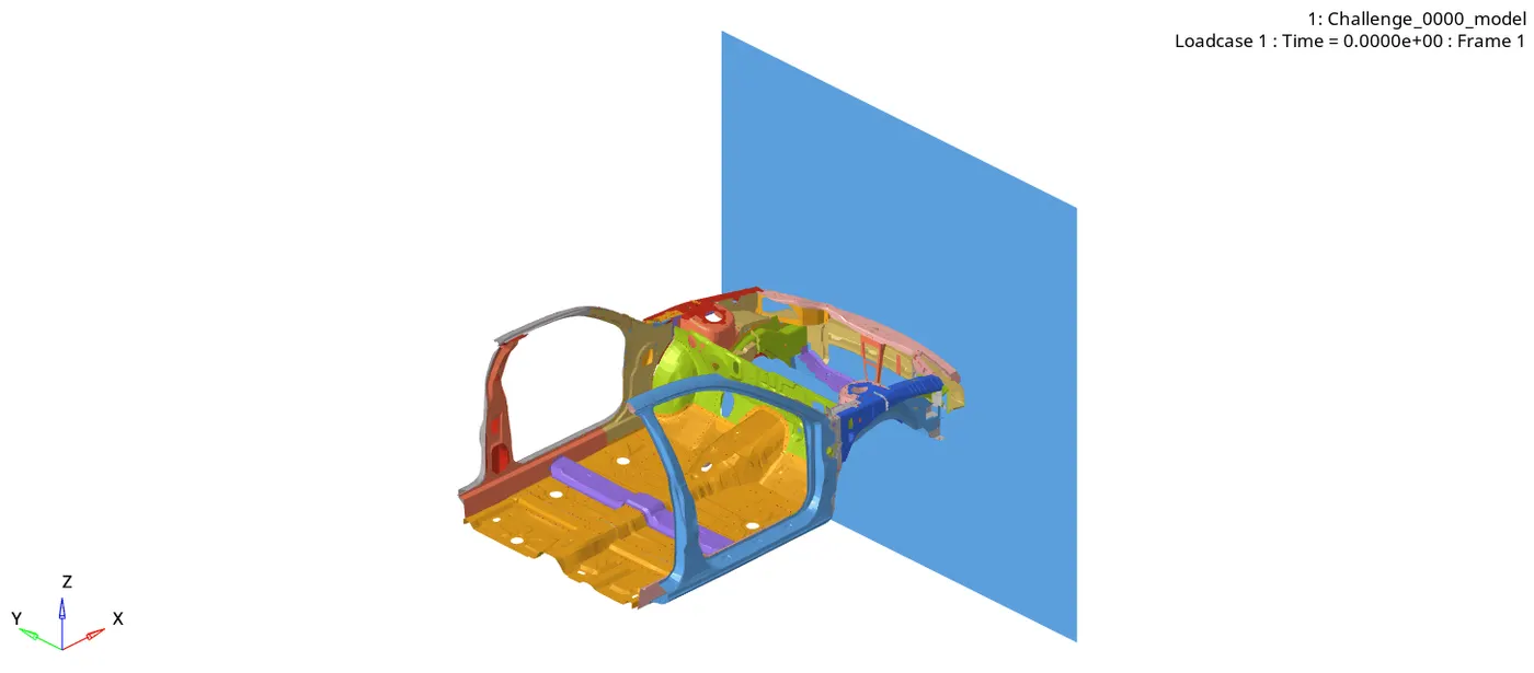
- The above is the simulated output of crash environment in which BIW is getting crashed upon rigidwall created.
FORCES ACTING AT SECTION - RAIL NODE :
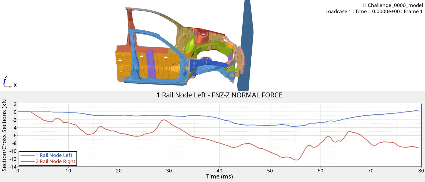
- The force acting on Right rail is greater than left Rail from the output graph.
- The peak force is of approx 3.8KN at 55ms on Left Node.
- The Peak force is of 12.1 KN at 55 ms on Right Rail.
- The simulation shows the deformation of the rails which passes the forces through the body, the negative force is due to change of the mov frame direction.
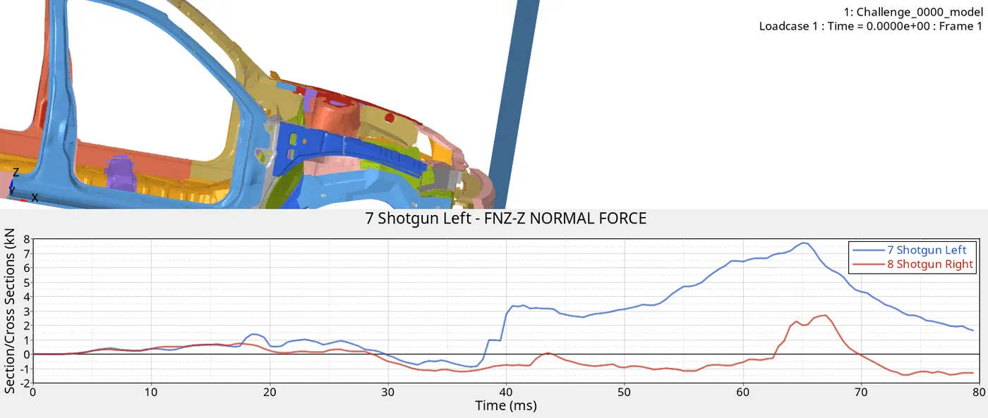
- The force acting on Left is greater than the right shotgun.
- The peak force is of 7.5KN at 65ms on Left Rail.
- The peak force is of 2.8KN at 65ms on Right Rail.
- The negative energy is due to impact of components on wall.
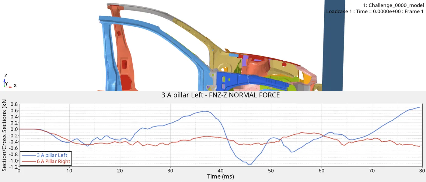
- The deformation in the A Pillar left is more than that of Right pillar.
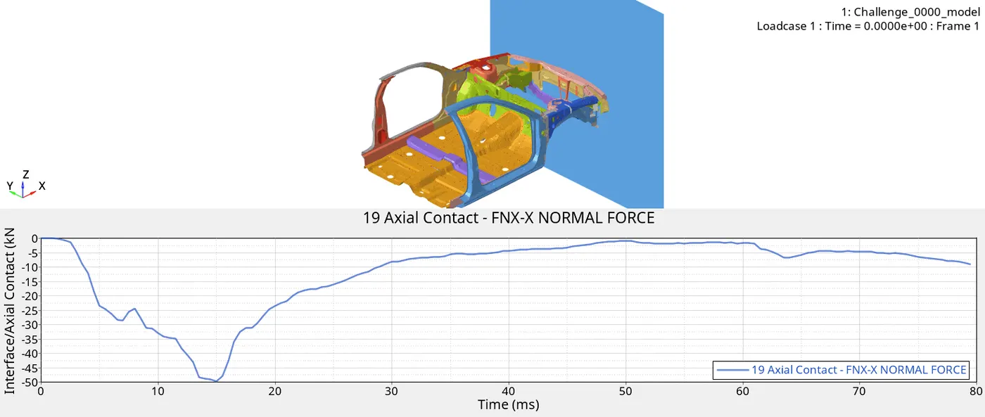
- The Peak force is of -50KN at 15ms.
- The deformation occurs in -x , hence the force is of negative value.
- The self contact with the rails bumper gets deformed in global -X
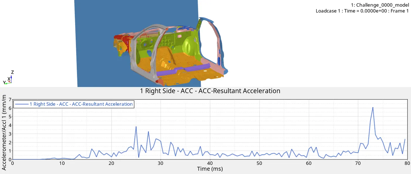
- The peak acceleration at Right side base of b pillar is of 6mm/ms.
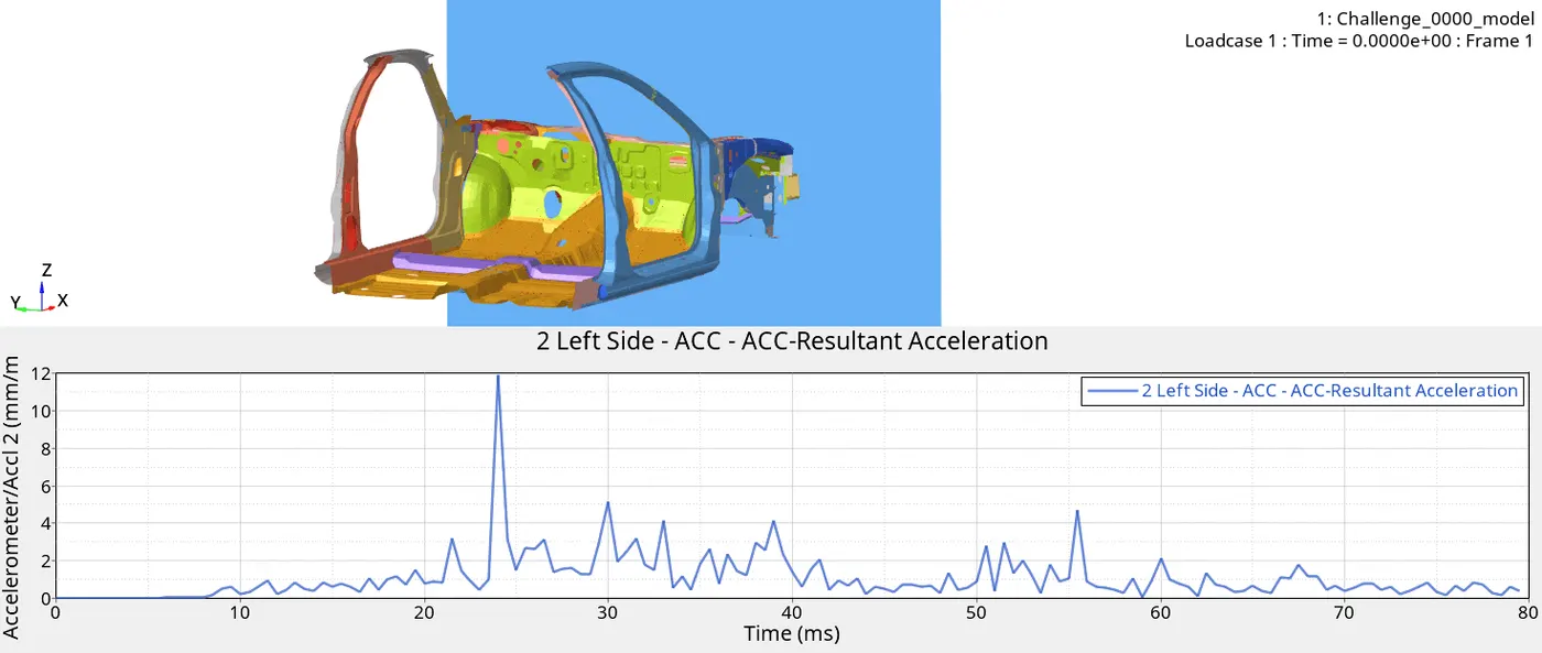
- The peak acceleration at Left side base of b pillar is of 12mm/ms
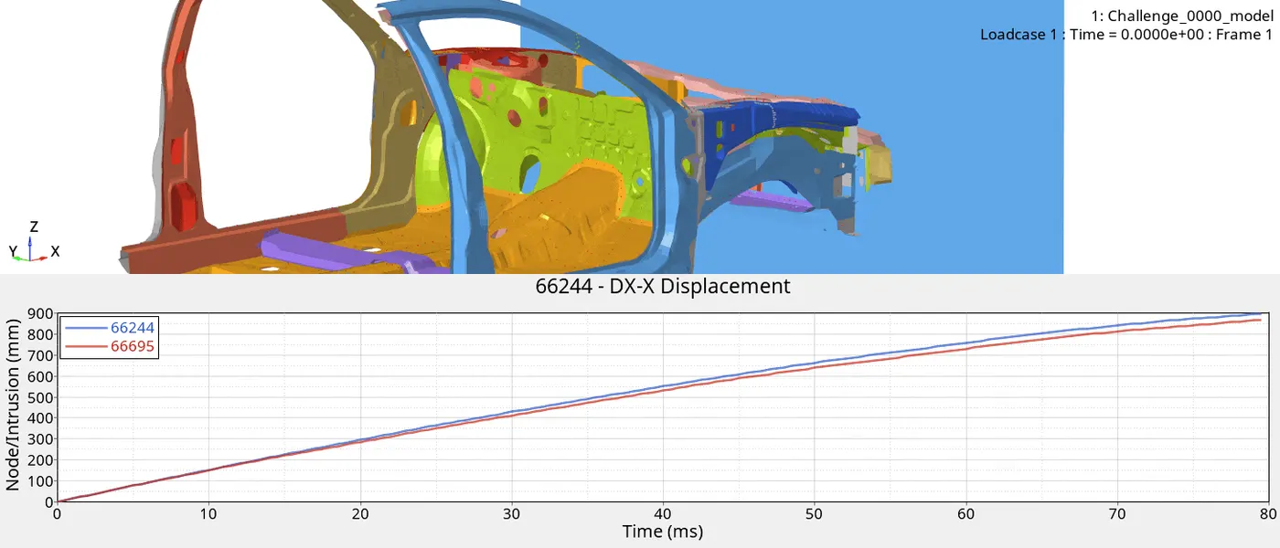
- In this the intrusion of the node (66244) is of 900mm.
- The intrusion of node (66695) is of 860mm.
- The displacement is gradual along 80ms.
ENERGY PLOT:
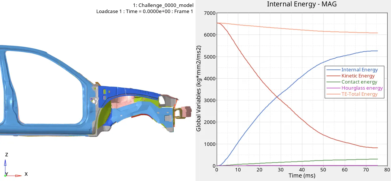
- The Contact energy gradually increase to max of 200, as the component gets crashed, elements and nodes comes in contact with each other.
- The Total energy is decreasing as there is an energy error in the component.
- The kinetic energy found to be max due to the initial velocity, it decreases to 900 as the deformation happens.
- Internal energy increases from zero to max of 5250.
- Hour glass energy is of 12.62, very minute which affects the total energy.
----------------------------------------------------------------------------------------------------------------------------------