FRONTAL CRASH OF NEON BiW MODEL USING HYPERMESH AND RADIOSS
Full Width Rigid Barrier
In recent years car structures have become stiffer. This has helped to reduce lower leg and head injuries as the passenger compartment is less prone to collapse. Higher structural stiffness however also means higher compartment decelerations, which need to be dealt with by the restraint systems in the front and rear seats during the crash. These decelerations can lead to severe injuries, especially to the chest of the more vulnerable, smaller or elderly occupants.CAR STRUCTURES HAVE BECOME STIFFER, THIS HAS HELPED TO REDUCE LOWER LEG AND HEAD INJURIES.Euro NCAP tests cars against a rigid barrier with full overlap at a test speed of 50 km/h. A small female frontal impact dummy is seated in the front driver’s seat and in the rear passenger side seat.This test places high demands on the restraint systems in front and rear seating positions. Strict limits are placed on the decelerations of the chest and on the degree of chest deflection and this, in turn, encourages manufacturers to fit more sophisticated restraints. The test complements the offset deformable test as a balance must be found between a restraint system that is stiff enough to restrain a male dummy in the 64km/h test and one that is compliant enough not to put injuriously high deceleration forces on a small female.
OBJECTIVE :
In this project the objective is to perform frontal crash of the given BIW component using HYPERMESH AND RADIOSS with below
INPUT REQUESTS
- Check unit system and either follow[Mg mm s] or [Kg mm ms].
- Create appropriate interface ,friction 0.2 and recommended parameters.
- Make sure of no penetrations and intersection.
- Correct rigid bodies if any issues.
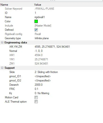
- Create rigid wall with friction 0.1.
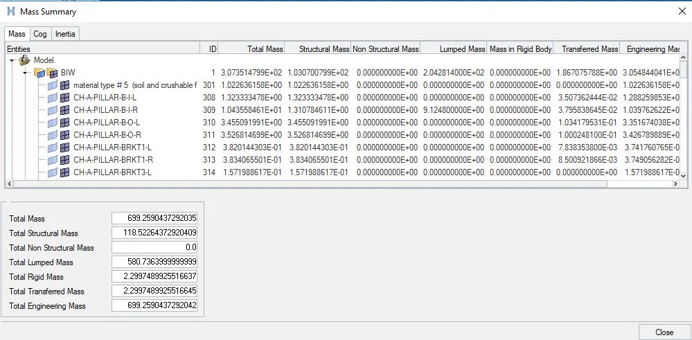
- Compare the model weight with the full scale 300k nodes model and use added masses to reach target weight 700kg while getting CG about the required range.
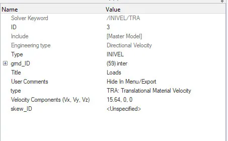
- Initial velocity 35 mph.
- Use model checker to ensure good quality.
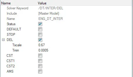
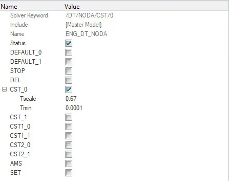
- Time-step :0.5 to 0.1 microseconds.
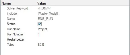
- Run 80 ms.
OUTPUT REQUESTS:
- Sectional force in the rails at location of indicated node 174247.
- Axial force received on the rails from bumper.
- Shotgun cross sectional forces.
- A pillar cross section.
- Acceleration curve received on the accelerometer at base of B pillar (on B pillar rocker).
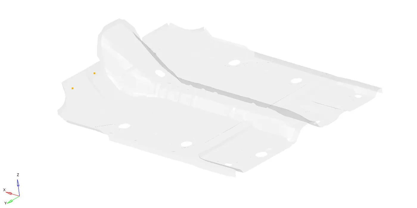
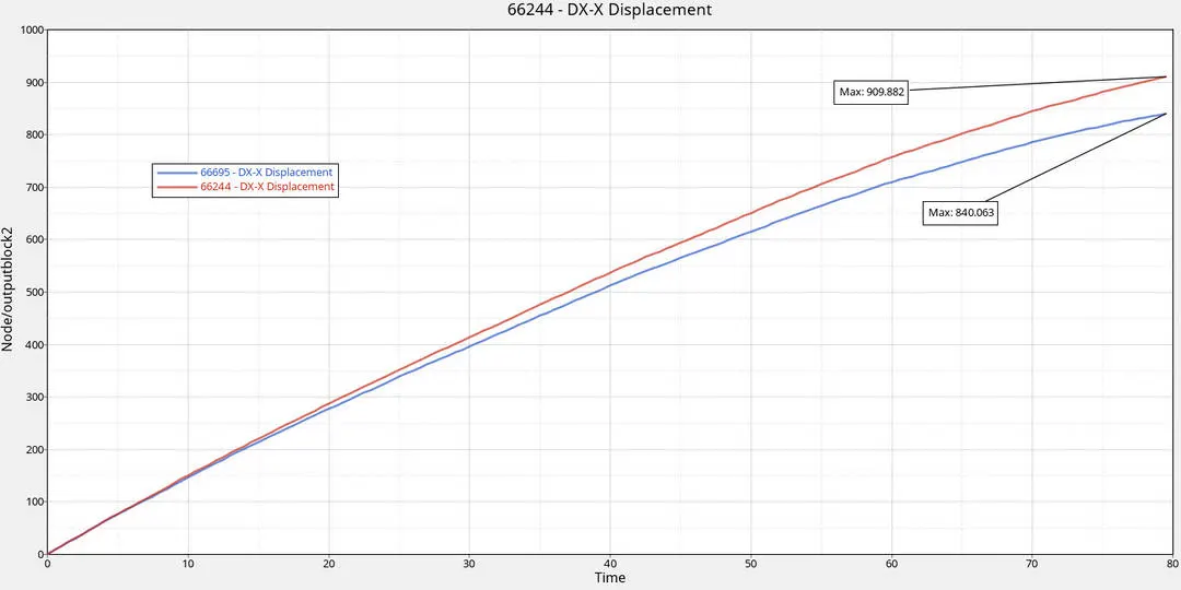
- Intrusions on the dash wall 66695,66244.
MODEL SETUP
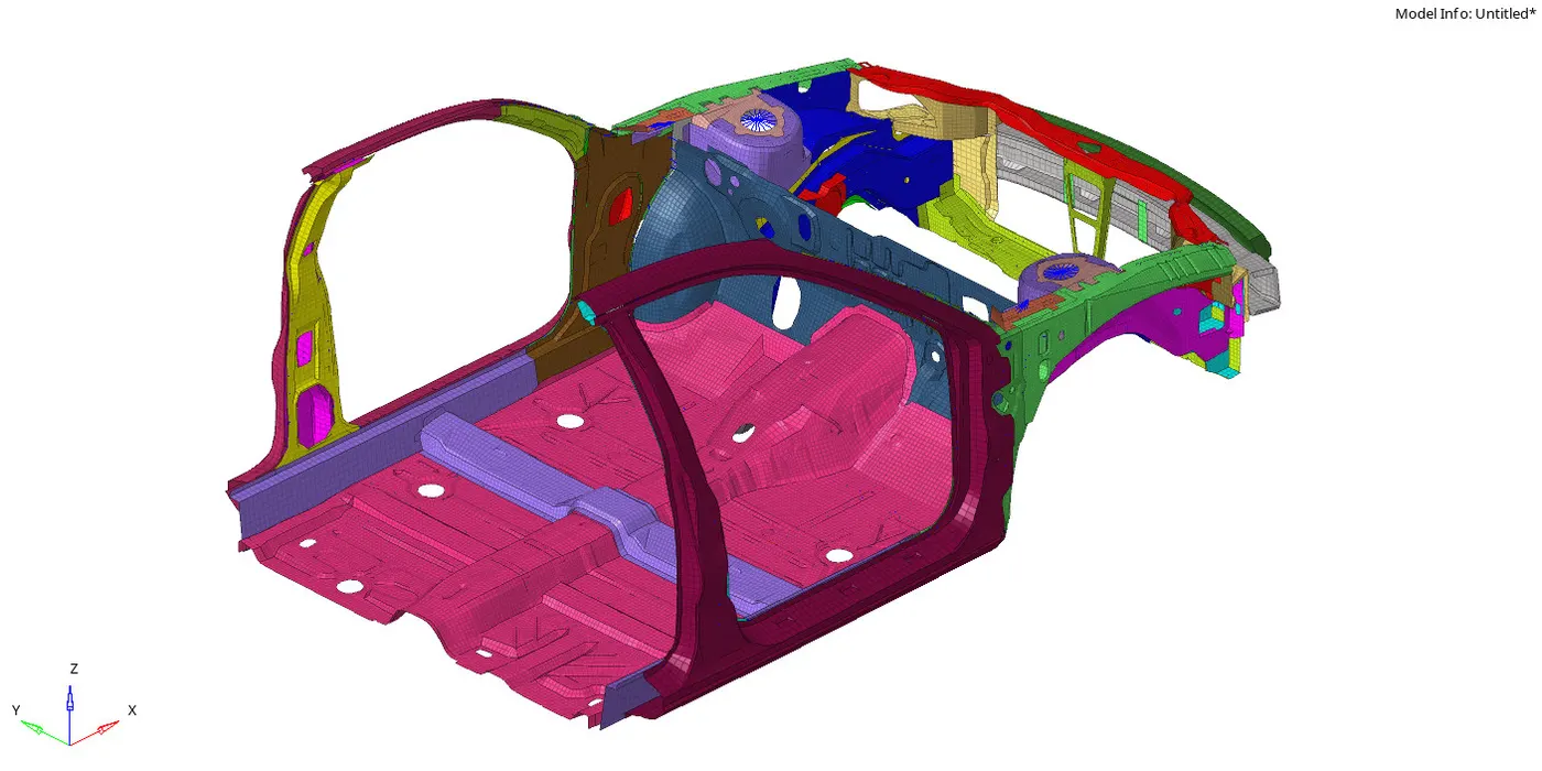
INPUT REQUESTs
- first the given neon_front0000.rad file is imported in radioss and unit system is set to [Kg,mm,ms] from Model--cards--begincards
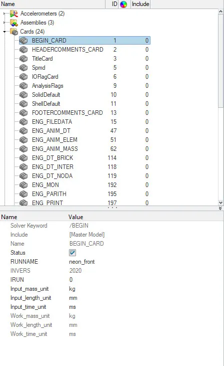
- Then type7 (Edge to surface) interface is created with recommended properties and with friction coefficient of 0.2
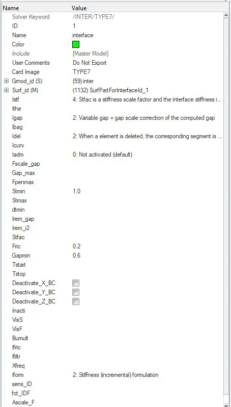
- Slave and mass nodes aare defined as in the below image
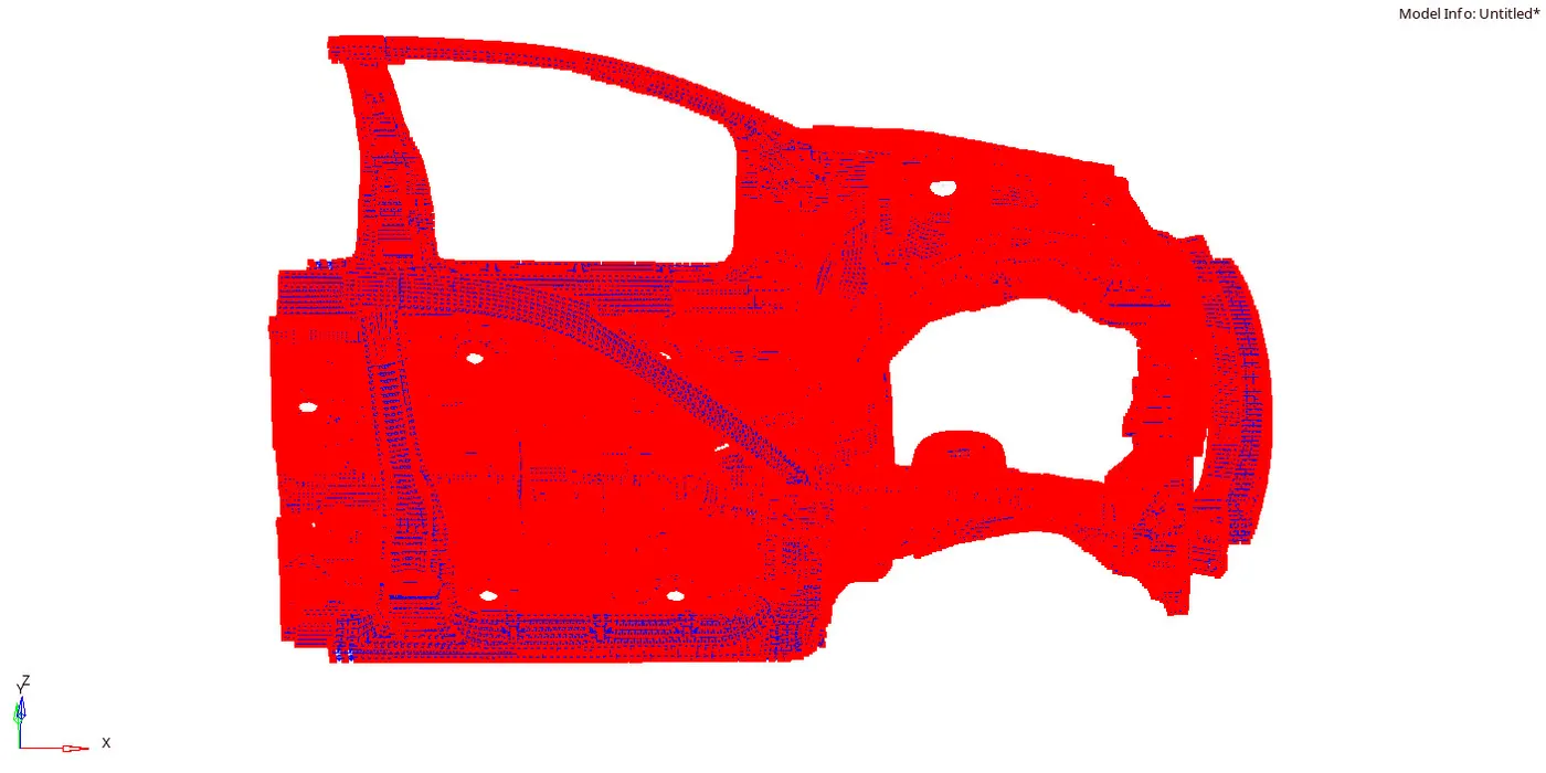
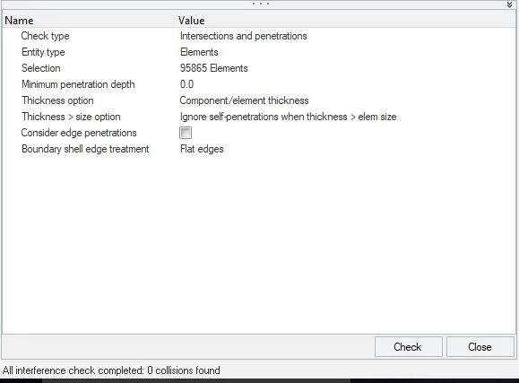
- Check for Penetrations and interference in hypermesh by Tools--penetration check
- infinte Rigid wall is created in hypermesh by BCS--create--Rigid wall
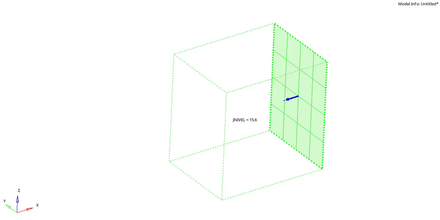
- Then initial Velocity of 35mph is applied to the components at Global X through Tools--create cards--Boundary conditions--INVEL/TRA and the Ground ID is selected as shown below
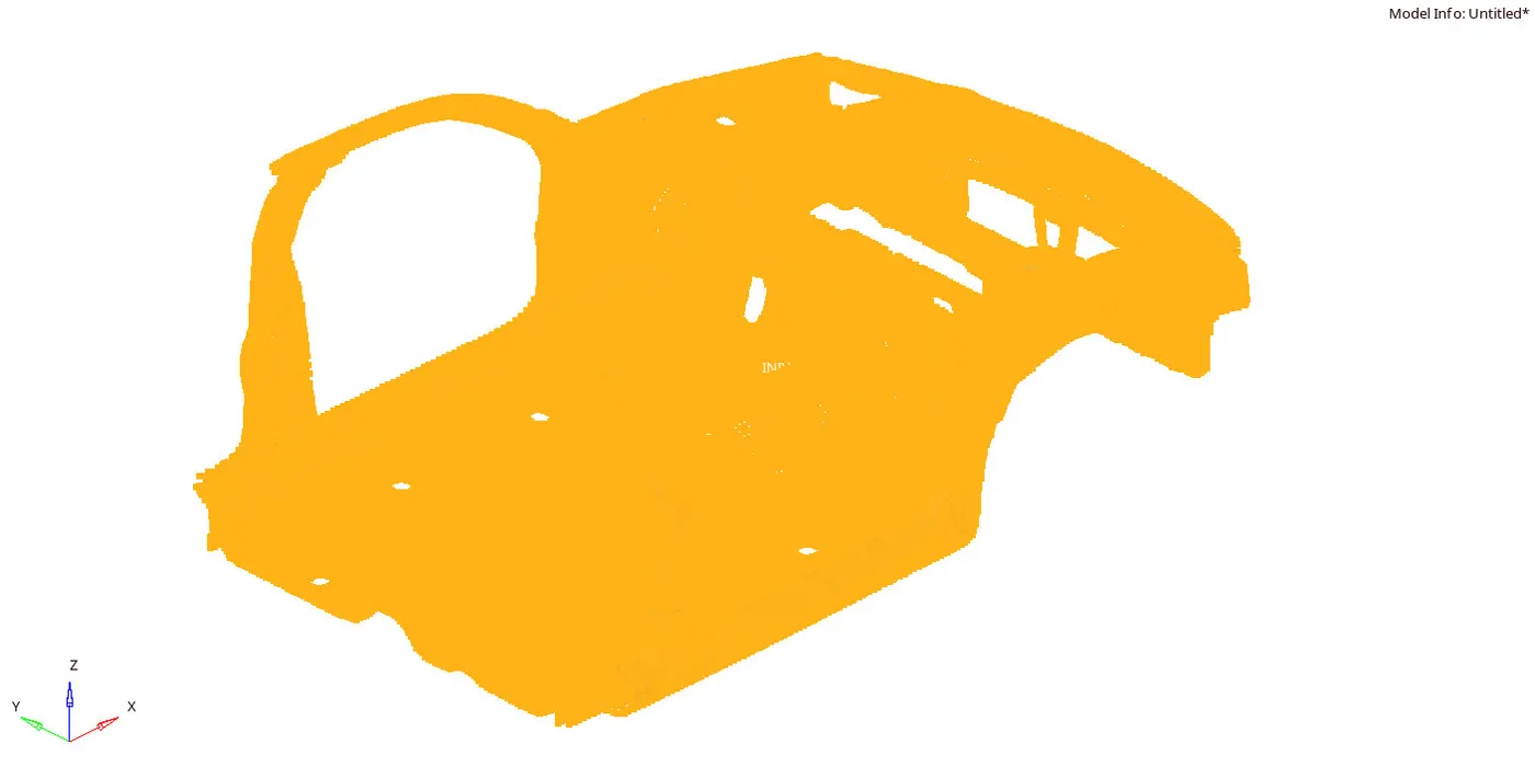
- Then the mass of 700kg is added based on the required COG
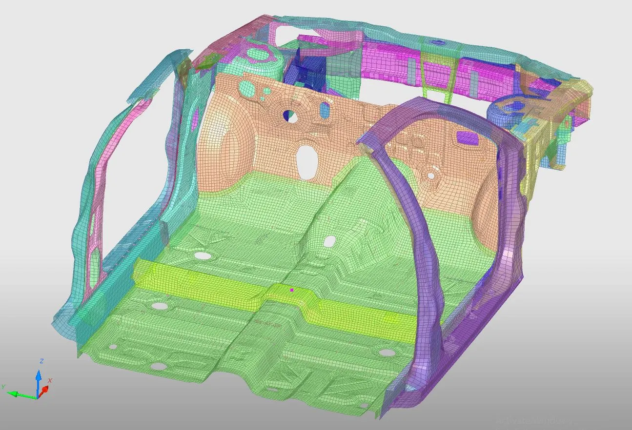
- Quality of the model is checked in hypermesh by (tools--modelchecker--radiossblock) and the errors were rectified .
- Here the crictial time step must be maintained within 0.1ms to 0.5ms
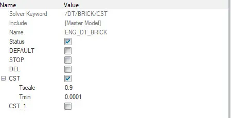
- The Tstop is set to 80ms in engine run card (Tools--createcards--Run)
OUTPUT REQUESTS
- CROSSECTIONAL FORCES
- RAILS
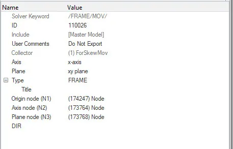
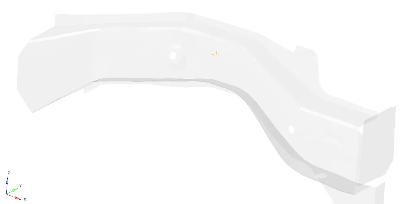
FRAME(TOOLS--createcards--frame--mov)
The origin is selected at the node 174247 then xaxis and xy plane is defined
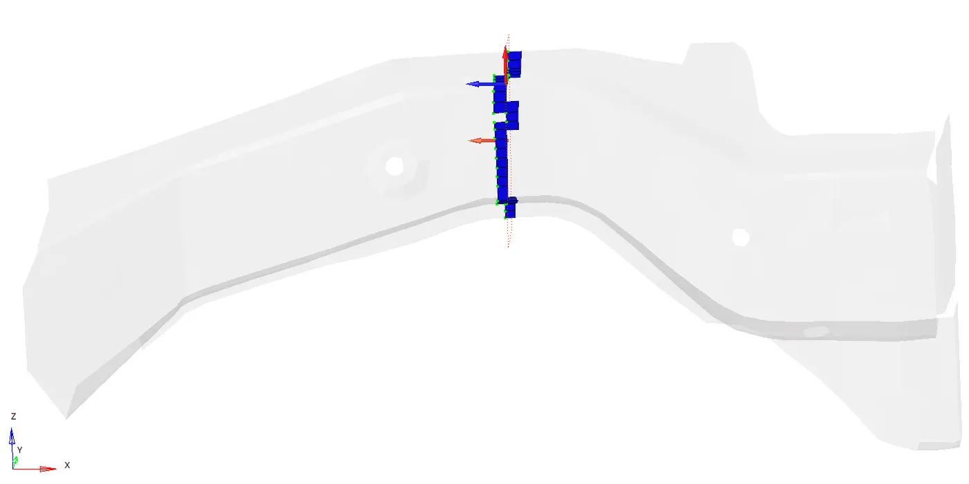
SECTION(TOOLS--createcards--SEC)
In section card the frame id and elements were selected in the respective elements are created.
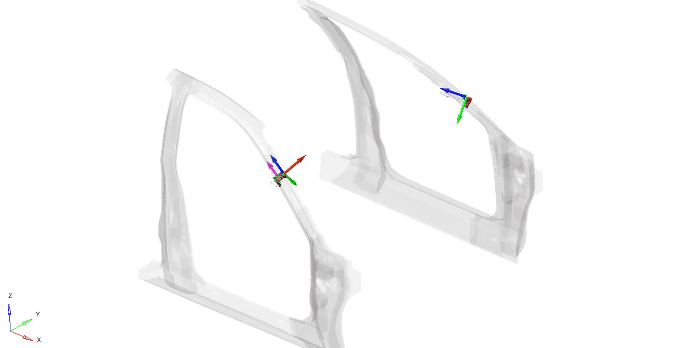
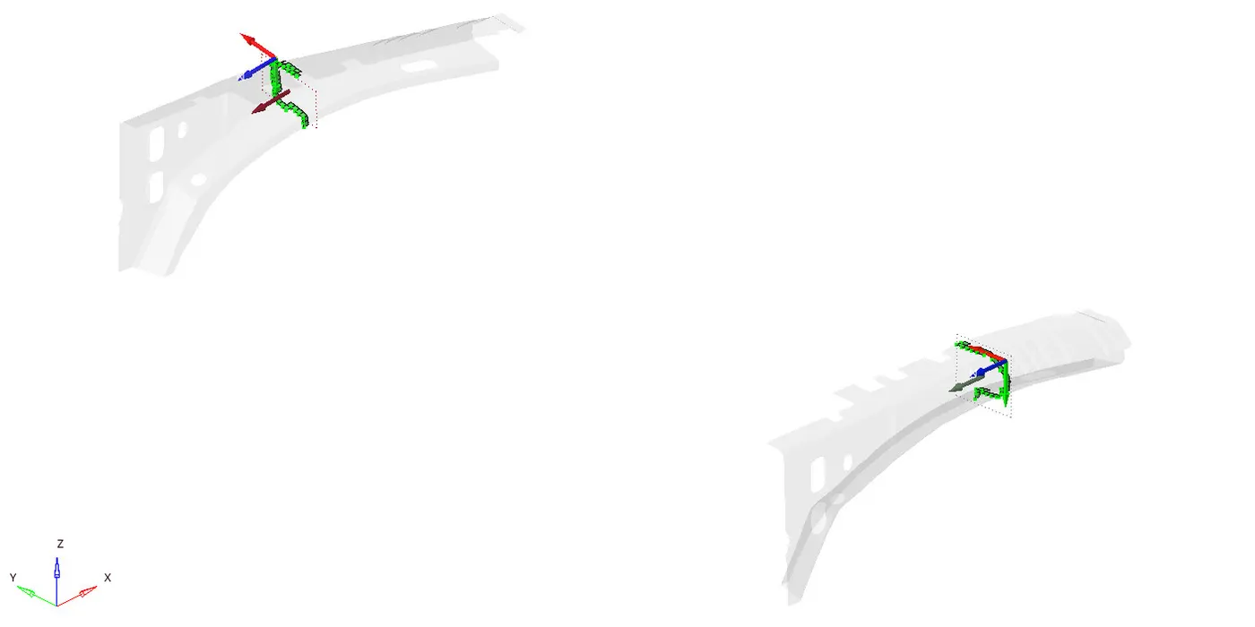
similarly the frame and sections are created at the respective components
- A pillar
- Shotgun
2.AXIAL FORCE (RAIL from BUMPER)
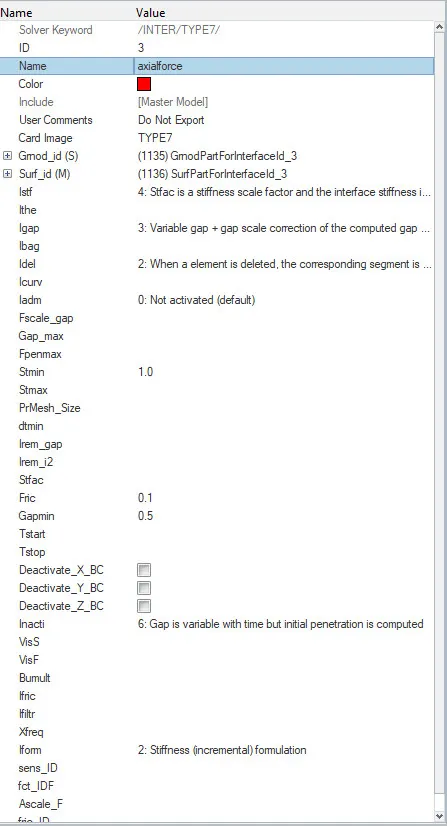
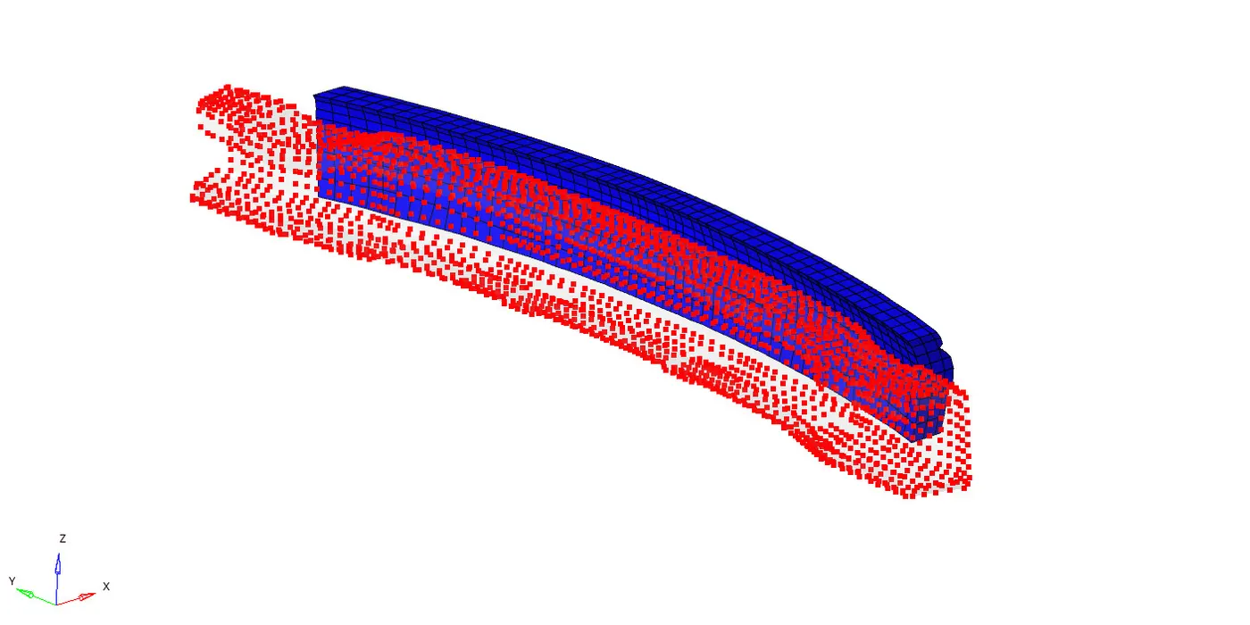
To know the axial force recieved on the rail we have to define the interface of type 7(Surface to node) between the rail(S) and bumper(M) with the recommended properties .
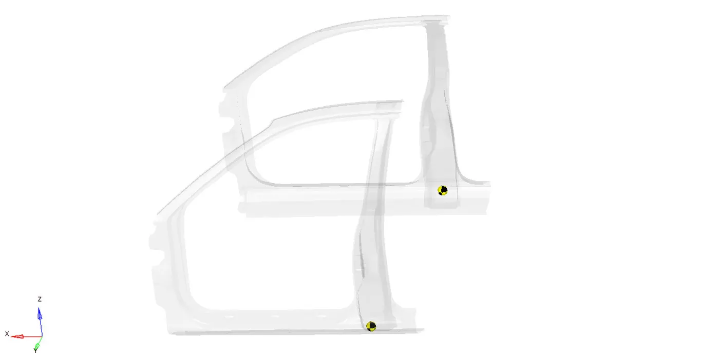
3.Accelerometer at base of B pillar
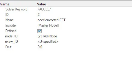
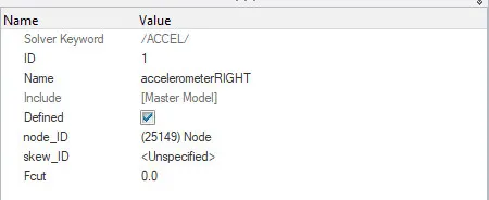
To know the acceleration at the b pillar accelerometer is created at the B pillar rocker in hyper mesh by (Tools--Create Cards--ACCEL)
The accelerometer is created at the base of the Bpillar rocker arm on both the sides. The accelorometer sensor senses the acceleration of the vehicle during the impact
3.Intrusions
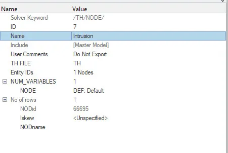
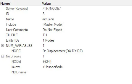
The intrusion on the dashwall at node 66695,66244 can be known by creating /TH/Node from the (Tools--create cards--TH--NODE) with respective node id
ANIMATION
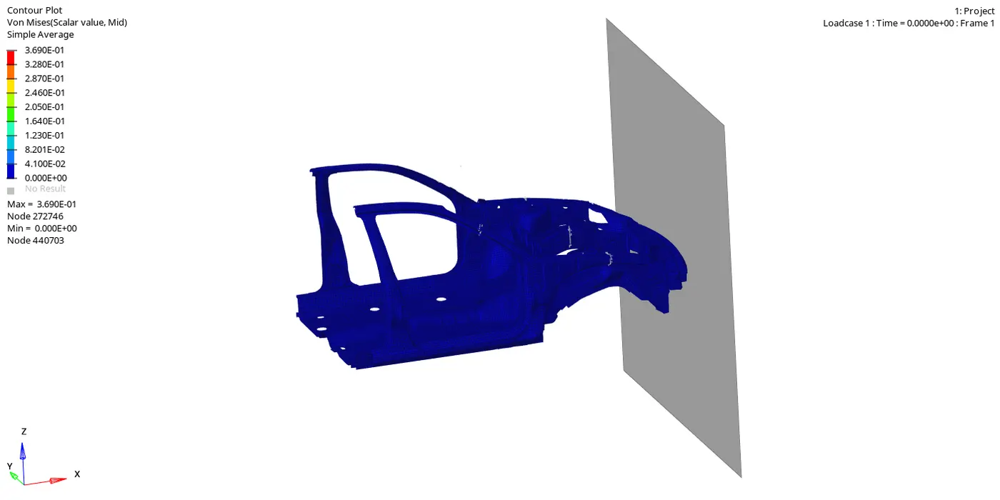
VONMISES
Von Mises stress is a value used to determine if a given material will yield or fracture. It is mostly used for ductile materials, such as metals. The von Mises yield criterion states that if the von Mises stress of a material under load is equal or greater than the yield limit of the same material under simple tension then the material will yield.
Here the maxium stress is obeserved is 0.3690KN @ node272746
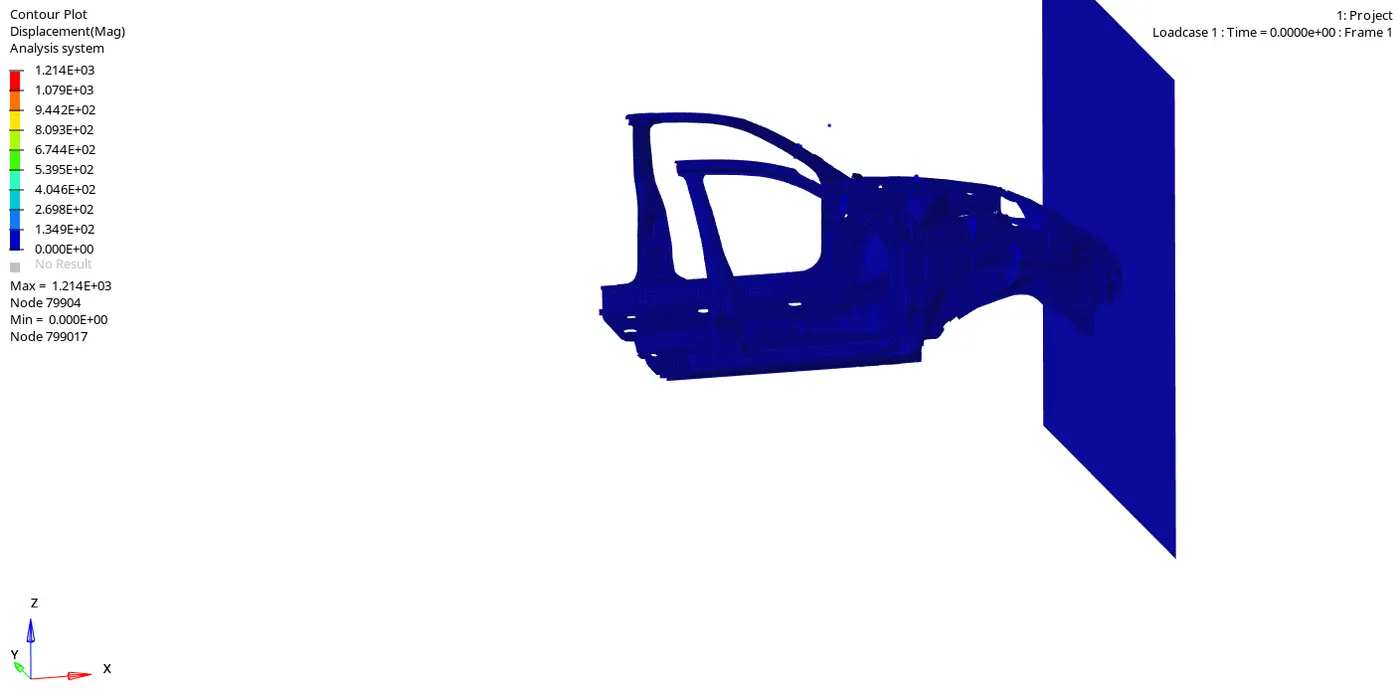
DISPLACEMENT
PLOTS
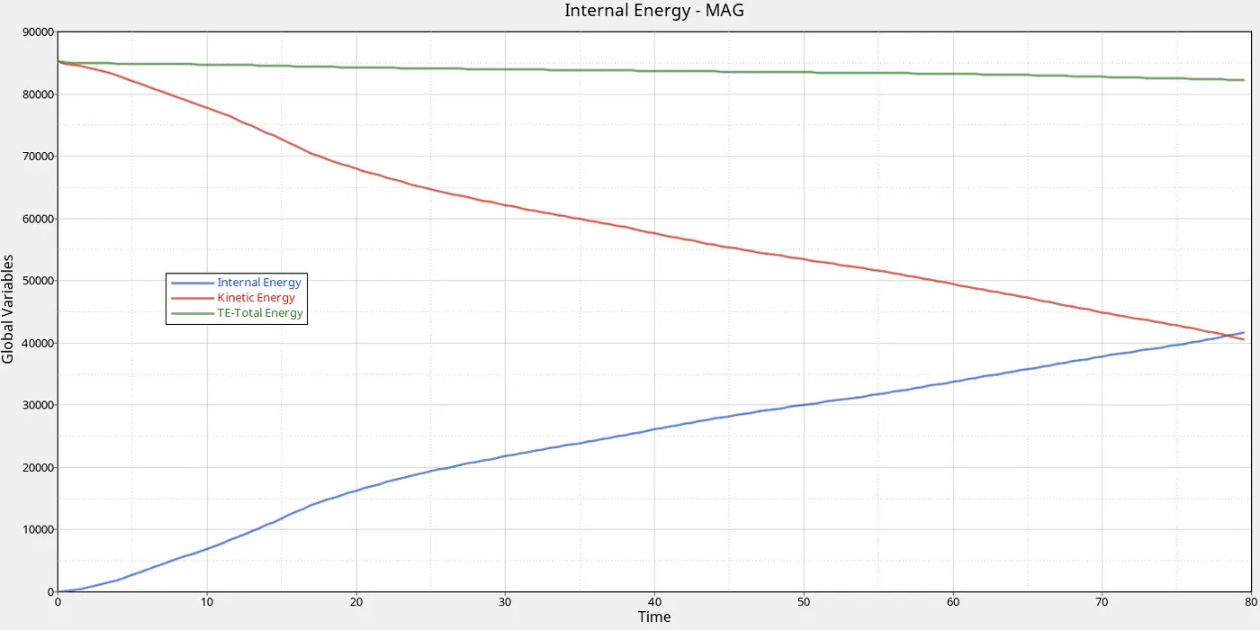
- ENERGY
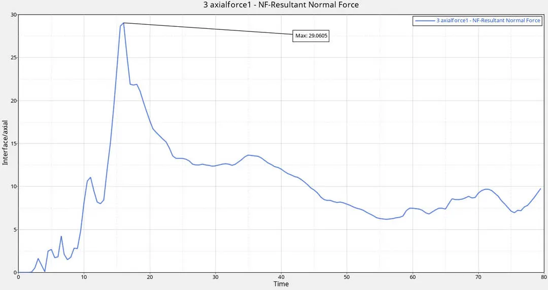
- AXIAL FORCE BUMPER TO RAIL
Bumper and the rails are important components in the car which should modeled and designed in way such that it can absorb maximum amount of energy during crash here in this model we can see the max force recieved on the rail is 16.47Kn within (0-5)ms
- CROSSECTIONAL FORCES
crossections were created inorder to know the amount of force recieved on the components and to validate the design and type of material used to model the components. so that the force experienced by the occupant area can be reduced.
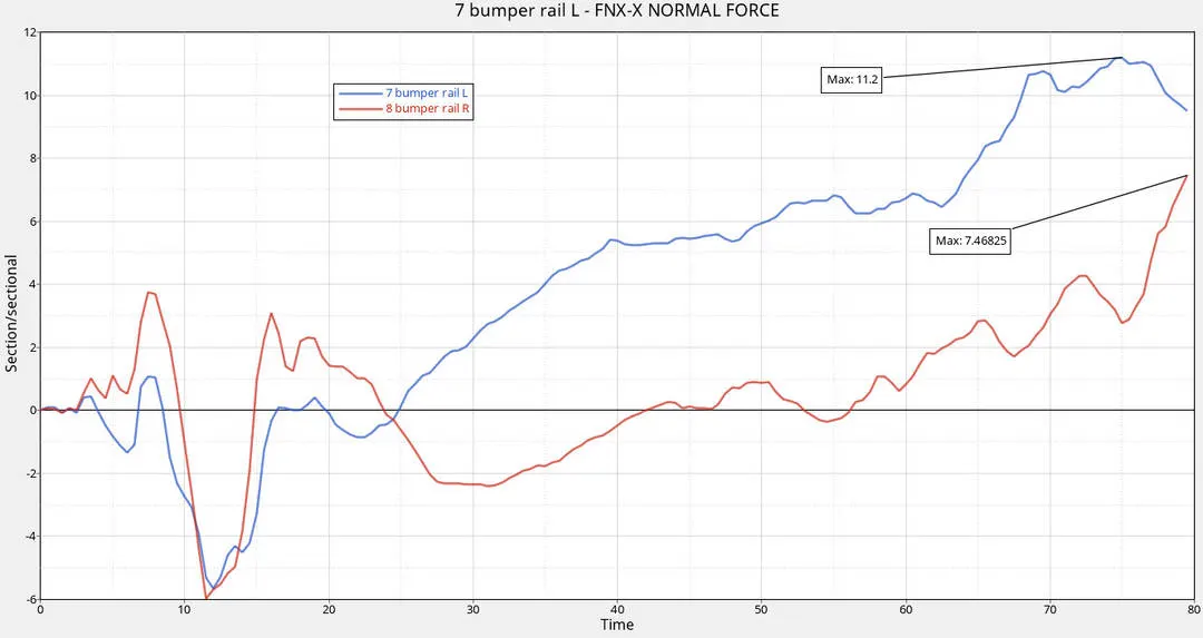
- BUMPER TO RAIL
From the plot we can see that the Left side of the rail recieves more amount of force at the end of the sumilation which is dependant upon the mass and acceleration so the acceleration.
Force recieved on the R apillar is 11.2 kN
Force recieved on the L apillar is 7.46 kN
- RAIL
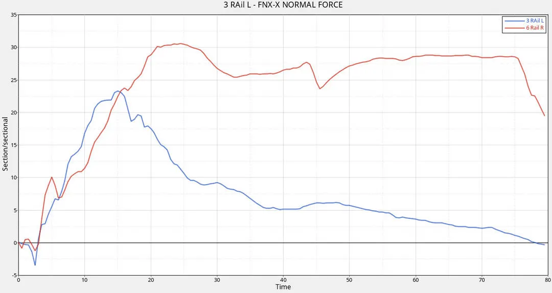
when the crash is occurs first of all the maximum amount of force is observed in the bumper then the Left side of the rails starts to absorb the force from (15)ms and the maximum force is about 23 kN Whereas in the right side of the rail the maximum force is 31.25 kN at 24ms
- SHOTGUN
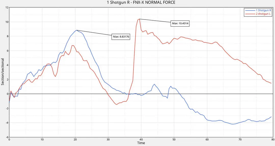
The above graph shows sectional forces on shotgun on the left and right sections of the car.
From the graph, there is a peak in the left shotgun at 35.5ms of magnitude 10.40KN
The maximum value of force has been recorded on right section at 21ms of magnitude8 .83KN
It clearly shows that the forces are very high in the left section.
- A PILLAR
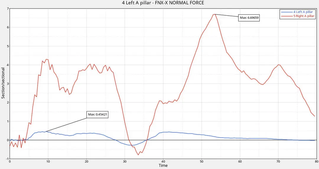
The above graph shows sectional forces on A-pillar.
The forces on A-pillar are fluctuating nature from the graph.
The forces are also low compared to shotgun and rails.
Maximum values are observed at the end of simulation on the left section and middle of simulation on the right section.
- ACCELERATION AT B PILLAR
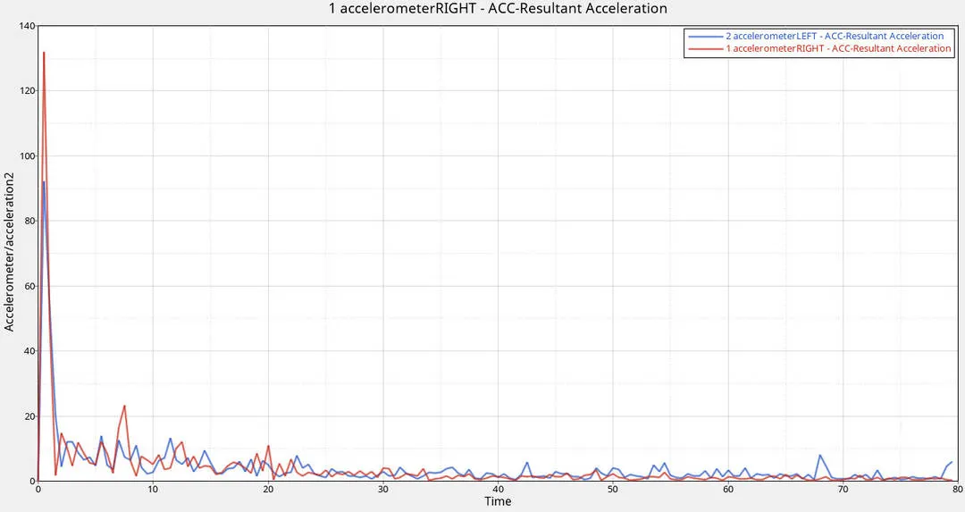
Acceleration of nodes on the rocker arm is plotted above.In the beginning, acceleration is high due to impact and gradually it decreased and maintained constant through the rest.
- INTRUSION
CONCLUSION
- More deformation on the left side of the vehicle has been observed from the above results.
- Sectional forces on the high on rails and second-highest on the shotgun and comparatively low on A-pillar. This implies that maximum forces have been transferred to rails and shotgun during impact.
- Hence, more robustness of the rails and bumper keeps occupants safe inside the car.